manuals.online logo
Brands
  1. Home
  2. •
  3. Brands
  4. •
  5. Honeywell
  6. •
  7. Relay
  8. •
  9. Honeywell X47 User manual

Honeywell X47 User manual

PN 292-118
Copyright 2013 INNCOM by Honeywell
X47 Universal Relay Pack
Installation Guide
Note: This picture is
for reference only.
The production
enclosure is
available only in
Warm Grey.
The X47 Universal Relay Pack (PN 201-147) is an INNCOM
Integrated Room Automation System (IRAS) device designed
for guestroom controls. The X47 provides five relay outputs
used to switch a variety of loads, including fan coil units
(FCU) and light-duty general loads. The X47 can integrate
with and receive data from multiple points throughout the
IRAS using low-voltage wired communication (S5bus),
infrared (IR) communication (when connected to IR Eye 5), or
radio frequency (RF) communication (when connected to a
PC502). The X47 comes in 24VAC (low-power) or 100-
277VAC (line-power) versions.
Installation
CAUTION!
• The X47 is intended for indoor use only.
• The X47 installer must be a trained, experienced
service technician.
• All wiring must comply with local codes and
ordinances.
• The X47 is intended for indoor use only.
• Failure to follow the instructions provided with the
product could damage the product or cause a
hazardous condition.
Wiring
Figure 1 shows the X47 line-voltage and 24VAC connectors;
Figure 2 shows the communication headers; and Figure 3
shows a typical connection to an FCU.
Figure 1 Connectors
Line-Voltage Connections: The phase (hot) and neutral
connections are defined on the product label.
Low-Voltage Power/Communications Connection: The
X47 can provide 12VDC 240mA output class-2 power and
S5bus for IRAS devices.
FCU
Typical Fan Coil Unit Connections
X07
HIGH FAN
MED FAN
LOW FAN
LOGIC BOARD
GND HEAT COOL VCOM FCOM NEU LINE
M
LOW MED HIGH
P1 P2 P3 P4 P5 P6 P7
P8
P9
P10
*Note: Typically Valve and Fan Power use L1/Line Power
*
HEAT
COOL
Earth
LINE/L1
NEUT/L2
Figure 3 Typical FCU Connections
!
Figure 2 X47 Headers
Figure 1 Communications Headers
Copyright 2013 INNCOM by Honeywell
PN 292-118
Mounting the X47
Use the supplied four 6/32 ½” screws to mount the X47
inside the NEMA enclosure or FCU using the four screw
holes in the bottom enclosure.
Ratings
The ratings given here and on the product should be
checked to make sure the product is suitable for the
application. Table 1 gives relay functions for the line-
power version; Table 2 gives the ratings for the low-power
model. Table 3 provides relay functions for typical
installations.
Table 1: X47 Relay Output Specifications,
110-277VAC Input model
Rating
Pin
Assignment
K1 3A, 277VAC Gen. Purpose
3.6FLA, 21.6LRA
P8
K2 3A, 277VAC, Gen. Purpose,
2.2FLA, 13.2LRA, 0.7A
sealed, 7A inrush
P9
K3 3A, 277VAC, Gen. Purpose,
2.2FLA, 13.2LRA, 0.7A
sealed, 7A inrush
P10
K4 3A, 277VAC, Gen. Purpose,
2.2FLA, 13.2LRA, 0.7A
sealed, 7A inrush
P2
K5 3A, 277VAC, Gen. Purpose,
2.2FLA, 13.2LRA, 0.7A
sealed, 7A inrush
P3
Common 1 K1, K2, K3 P5
Common 2 K4, K5 P4
Table 2: X47 Relay Output Specifications,
24VAC Input model
Typical Operation
Pin Assignment
K1 1.0A Sealed, 10A inrush,
class-2 pilot Duty
P4
K2 1.0A Sealed, 10A inrush,
class-2 pilot duty
P5
K3 1.0A Sealed, 10A inrush,
class-2 pilot duty
P10
K4 1.0A Sealed, 10A inrush,
class-2 pilot duty
P7
K5 1.0A Sealed, 10A inrush,
class-2 pilot duty
P6
Common 1 K1, K2, K3 P9
Common 2 K4, K5 P8
Table 3. X47 Relay Functions for Typical Installations
4 Pipe, 3
Fan, Heat
/ Cool
FCU
2 Pipe, 3
Fan, Cool
Only FCU
Heat Pump,
2 Fan 2nd
Stage Heat
Heat
Pump, 3
Fan
Speeds
PTAC, 2
Fan with
Heat Strip
K1 High Fan High Fan High Fan High Fan High Fan
K2 Medium
Fan
Medium
Fan
W2 2nd
Stage Heat
Medium
Fan
Not
Connected
K3 Low Fan Low Fan Low Fan Low Fan Low Fan
K4 Cool
Signal
Cool
Signal
Y-
Compressor
Y-
Compresso
r
Y-
Compressor
K5 Heat
Signal
Not
Connected
B/O-
Reversing
Valve
B/O-
Reversing
Valve
W-Heat
Commissioning
To participate in the network, the X47 must be
commissioned by teaching it identification information. The
following commissioning instructions use an X47
connected to a PC502 on the S5bus (for 2.4 GHz wireless
RF communications) and an E529 thermostat:
1. Power up the X47 (LED blinks rapidly).
2. Enter the Service Mode on the e529 thermostat (press and hold
the °F/°C button; press and release the OFF/AUTO button;
press and release the DISPLAY button; release the °F/°C
button).
3. On the E529 LCD, scroll to Adr and press DISPLAY.
4. Set the address to teach the X47 (typically 14).
5. Press OFF/AUTO. The display will show bnd.
6. Use a small point (e.g., the end of a straightened paper clip) to
press the Bind switch on the X47 once. This sends a Bind
request toward the thermostat.
7. The thermostat will send a Bind offer to the X47. If it is accepted,
the thermostat will buzz multiple times. The X47 will reset.
8. Test the X47 functionality.
Table 4. Technical Specifications
X47.H Class-2 Output
Voltage/Power 12VDC, 240mA (See table below
to determine final output power)
X47.L Class-2 Output
Voltage/Power 12VDC, 200mA
Parameter Memory Non-volatile
Temperature range,
Operating Storage 32 to 140 degrees F (0 to 40
degrees C)
-40 to 158 degrees F (-40 to 70
degrees C)
15 to 99 percent RH
Mounting 4 hole mounting 6/32” bit, ½”
screw
Dimensions 2 ¾” W x 3 ½” H (excluding screw
tabs) x 1 ½” D (at deepest part)
70 mm W x 88 mm H x 38 mm D
PN 292-118
Approvals UL, FCC, IC, CE MARK, CCC
Current consumption is determined using the following
formula: 30mA + (n × 20mA) where 30mA is the current
consumption of the logic board and n= the number of
actuated relays.
Table 5. Current Consumption
Configuration Maximum Load (including
logic board)
All relays actuated 130mA
Note: Current consumption values of the X47 with actuated
relays should be deducted from class-2 output power rating in
Table 3 in order not to overdrive the power supply. The X47
should not be used to provide more than 70mA of external
class-2 power.

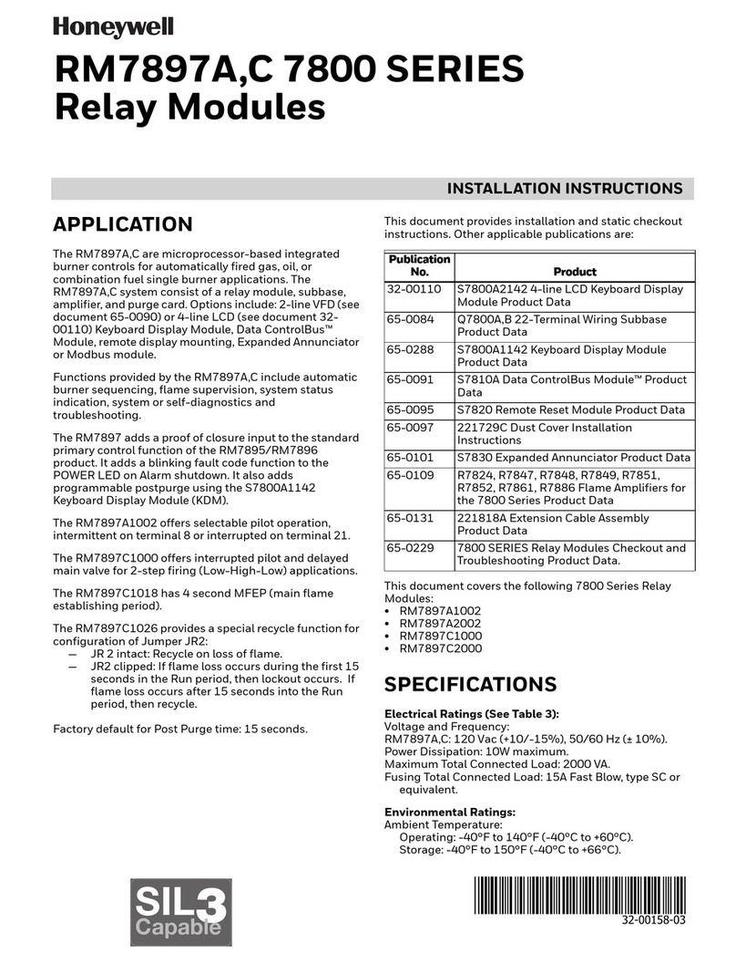
This manual suits for next models

1

Other Honeywell Relay manuals

Honeywell R132A Quick start guide

Honeywell

Honeywell R132A Quick start guide

Honeywell Aquastat L8148A Operation manual

Honeywell

Honeywell Aquastat L8148A Operation manual

Honeywell Silent Knight SK-Relay User manual

Honeywell

Honeywell Silent Knight SK-Relay User manual

Honeywell ADEMCO 5800RL Assembly instructions

Honeywell

Honeywell ADEMCO 5800RL Assembly instructions

Honeywell RP470A User manual

Honeywell

Honeywell RP470A User manual

Honeywell 7800 SERIES User manual

Honeywell

Honeywell 7800 SERIES User manual

Honeywell BDR91 User manual

Honeywell

Honeywell BDR91 User manual

Honeywell R841C-E User manual

Honeywell

Honeywell R841C-E User manual

Honeywell Aquastat L8148A User manual

Honeywell

Honeywell Aquastat L8148A User manual

Honeywell 301RW User manual

Honeywell

Honeywell 301RW User manual

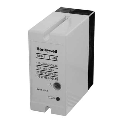
Honeywell R4343D User manual

Honeywell

Honeywell R4343D User manual

Honeywell RM7897A User manual

Honeywell

Honeywell RM7897A User manual

Honeywell RA889A User manual

Honeywell

Honeywell RA889A User manual

Honeywell TRADELINE R8184G User manual

Honeywell

Honeywell TRADELINE R8184G User manual

Honeywell 7800 SERIES User manual

Honeywell

Honeywell 7800 SERIES User manual

Honeywell 7800 SERIES RM7895A Operation manual

Honeywell

Honeywell 7800 SERIES RM7895A Operation manual

Honeywell Aquastat L8148A User manual

Honeywell

Honeywell Aquastat L8148A User manual

Honeywell Notifier SKBR3N User manual

Honeywell

Honeywell Notifier SKBR3N User manual

Honeywell NOTIFIER FRM-1 User manual

Honeywell

Honeywell NOTIFIER FRM-1 User manual

Honeywell Farenhyt Series User manual

Honeywell

Honeywell Farenhyt Series User manual

Honeywell TRADELINE R182J User manual

Honeywell

Honeywell TRADELINE R182J User manual

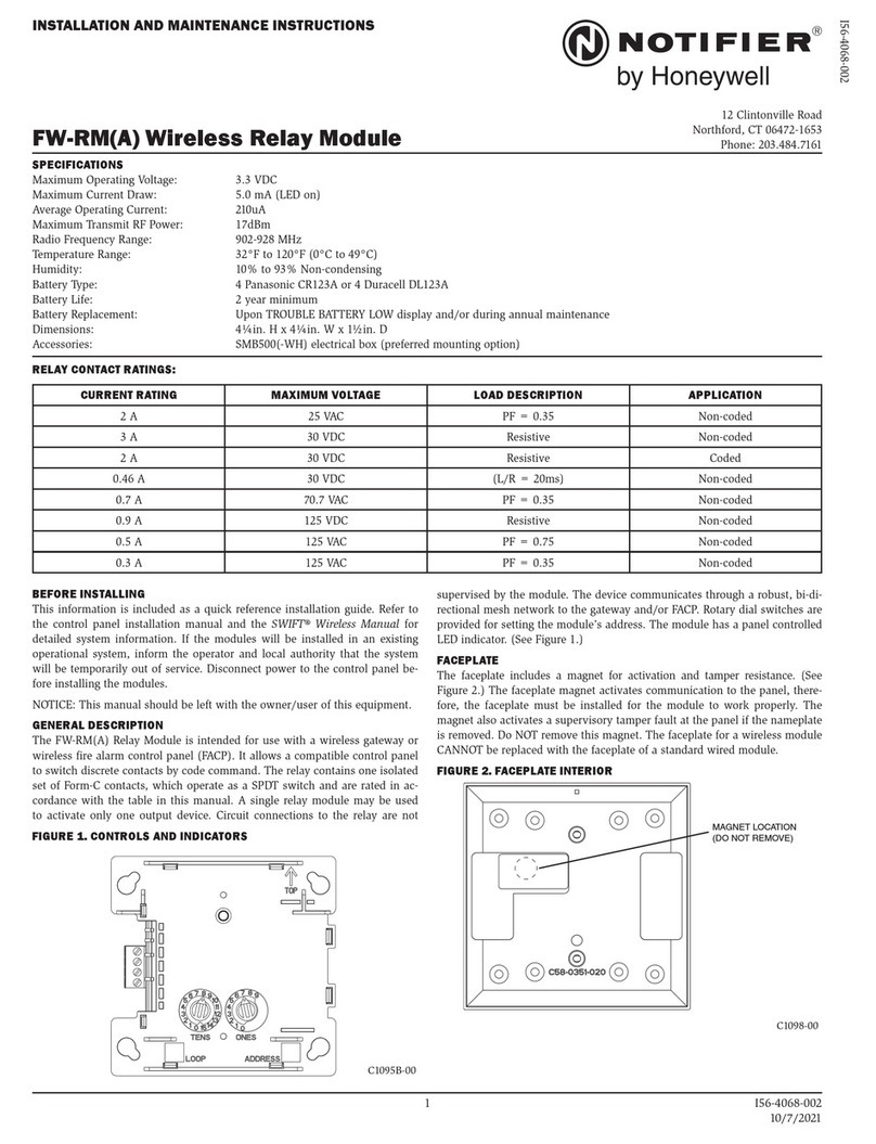
Honeywell NOTIFIER FW-RM User manual

Honeywell

Honeywell NOTIFIER FW-RM User manual

Honeywell SeqLED E SET-30 User manual

Honeywell

Honeywell SeqLED E SET-30 User manual

Honeywell 7800 SERIES User manual

Honeywell

Honeywell 7800 SERIES User manual

Popular Relay manuals by other brands

Hella 4RD 980 830-001 / 3099 Operation and installation instructions

Hella

Hella 4RD 980 830-001 / 3099 Operation and installation instructions

Simons Voss Technologies SREL.AV quick guide

Simons Voss Technologies

Simons Voss Technologies SREL.AV quick guide

Rievtech PR-6DC-DA-R user manual

Rievtech

Rievtech PR-6DC-DA-R user manual

MULTISPAN CPR 126 manual

MULTISPAN

MULTISPAN CPR 126 manual

Omron J7TKN - datasheet

Omron

Omron J7TKN - datasheet

Schrack Technik AMPARO ZRAE0011 Assembly and installation instruction

Schrack Technik

Schrack Technik AMPARO ZRAE0011 Assembly and installation instruction

BERNSTEIN SCR ON4-W22-3.6-S Installation and operating instructions

BERNSTEIN

BERNSTEIN SCR ON4-W22-3.6-S Installation and operating instructions

TTK FG-RELAYS quick start guide

TTK

TTK FG-RELAYS quick start guide

TIS ACM-2R-2Z installation manual

TIS

TIS ACM-2R-2Z installation manual

Cooper UM30 Operation manual

Cooper

Cooper UM30 Operation manual

Westinghouse TR-1 Installation, operation & maintenance instructions

Westinghouse

Westinghouse TR-1 Installation, operation & maintenance instructions

ABB CT-S Series Operating and installation instructions

ABB

ABB CT-S Series Operating and installation instructions

Siemens SIRIUS SRF2 Series operating instructions

Siemens

Siemens SIRIUS SRF2 Series operating instructions

GMI D5095S instruction manual

GMI

GMI D5095S instruction manual

GE IFC51AD instructions

GE

GE IFC51AD instructions

ZIEHL VG1200 quick guide

ZIEHL

ZIEHL VG1200 quick guide

EOS LSG 10 CA Installation and operating instructions

EOS

EOS LSG 10 CA Installation and operating instructions

koban KPHD-NFC-ASTRO3 operating manual

koban

koban KPHD-NFC-ASTRO3 operating manual

manuals.online logo
manuals.online logoBrands
  • About & Mission
  • Contact us
  • Privacy Policy
  • Terms and Conditions

Copyright 2025 Manuals.Online. All Rights Reserved.