manuals.online logo
Brands
  1. Home
  2. •
  3. Brands
  4. •
  5. Honeywell
  6. •
  7. Thermostat
  8. •
  9. Honeywell DT70 Series User manual

Honeywell DT70 Series User manual

EN1001R0 KO06 2000
!"#$%&'()'&
!"#"$%&'(%)*+,"&'$-./0,1$%$1
2*3"3.''(%)*+,"&'+,)$/,&
*(+!,-"%&*'-).)-/")+0%&1''"
/**2)-/")+0
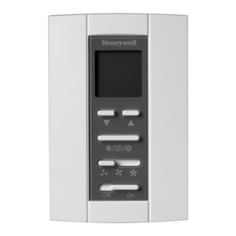
The DT70 digital thermostats are designed for ON/OFF
control of the valve, or the valve and fan in 2-pipe fan-
coil applications and also one-stage compressors in
DX-type equipment.
The thermostat operates an on/off valve to provide
control at the desired setpoint temperature.
Fan-coil thermostat models are available with constant
or cycled fan operation, and have a three-speed fan
selector switch with low, medium and high settings.
The fan can also be controlled from the thermostat. In
some cases it is wired to run continuously, and can be
switched off with the system ON/OFF switch.
Heat/cool changeover operation is also possible on all
versions. This function can be accomplished by
changing the Heat/Cool parameter in SETUP mode.
.'/",('&
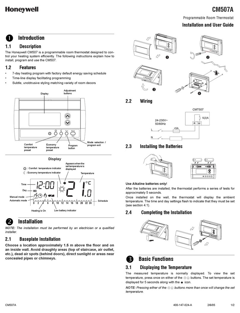
•Elegant styling with digital display makes
thermostat well harmonised with any interior
decoration of office or hotel
•Digital display of room ambient temperature, with
display of user selected setpoint on demand
•Push button adjustment of setpoint
•Push button setting of Heat/Cool changeover
•Switches allow manual control of system operation
and fan speed
•Thermostat mounts directly onto a wall, a standard
65365mm junction box (hole pitch 60mm) or a
85385mm junction box
•Ability to set minimum relay off-times (heating or
cooling) for applications requiring compressor short-
cycle protection (0~10min.)
•Ability to set control-off-times for applications
requiring starting-time reservation (0~24hr.)
•Ability to display temperature sensor failure for
easier troubleshooting
•EEPROM permanently retains user settings in the
event of power loss
•Suitable for use with Honeywell VC4000/VC6000
series and V4043/V4044 valves and compressor
starters/relays up to 2A full load rating
Contents
Application ………………………………………………… 1
Features …………………………………………………… 1
Specifications ……………………………………………... 2
Installation …………………………………………………. 3
Wiring diagram ……………………………………………. 4~5
Operation ………………………………………………….. 6
DT70 FAN -COIL THERMOSTATS
EN1001R0 KO06 2000 2
&*'-).)-/")+0&
Table 1. Model selection guide
Application Fan Operation Switches Supply voltage
Model
Cycled /
Constant On / Off
(SPDT) 3-Speed
Fan
(SP3T)
Vac±10%,
50/60Hz
DT70-F002ET 2-pipe Fancoil Cycled Yes Yes 220
DT70-F012ET 2-pipe Fancoil Cycled Yes Yes 110
DT70-F003ET 2-pipe Fancoil+Remote control of Chiller Constant Yes Yes 220
Setpoint range :5~35o
Display and
setting unit :0.5o
Differential :1
o max (0.5otyp)
Thermostat
switch :1 S.P.D.T. relay
Control
Performance :ON/OFF control
Electrical ratings :4(2) A, 220 V~ , 12A inrush
Typical loads are fans, zone valves and
relays
Operational life :Greater than 100,000 cycles (all loads)
for thermostat contacts at 220 V~ Greater
than 10,000 operations for all manually
operated switches
Mounting :Mounts directly onto wall or wall-box - a
standard 65x65mm junction box (hole
pitch 60mm) or a 85385mm junction box.
Mounting screws supplied
Wiring :7 or 9 screw –in terminals per unit,
capable of accepting 18~26AWG wires
per terminal.
Enclosure :Plastic 2-piece housing (front cover, rear
cover)
Dimensions :76 x 125 x 30mm(W x H x D).
:
Environmental
requirements
:Operating temperature range 5 to 45oC
Shipping and storage temperature range
-20 to 55oC.
Humidity range 5 to 95% rh, non-
condensing at 26o.
!"0.)1",)1
Fig. 1. DT70 Dimensions (in mm)
DT70 FAN -COIL THERMOSTATS
EN1001R0 KO06 2000
3
23456738
The DT70 Series thermostat is the temperature control element
in the fan-coil or air-conditioning system, and must be located
about 1.5m above the floor in a position with good air
circulation at room temperature. Do not mount it where it could
be affected by :-
-draughts or dead spots behind doors or in corners
-hot or cold air from ducts
-radiant heat from the sun or appliances
-unheated (uncooled) areas such as an outside wall
behind the thermostat
-concealed pipes or chimneys
)0&"/22/")+0
93:8678;%6<=%6<=>?3@656
The DT70 Series thermostat can be directly mounted on the
wall or on either a 65x65mm standard junction box or a
85x85mm junction box. Mounting screws are supplied for both
alternatives.
IMPORTANT
The installer must be a trained service engineer
Disconnect the power supply before beginning installation
•!Separate the base
from the main unit •!Base mounting •!Wiring •!Carefully insert the
main unit on the base
Fig.2. DT70
Mounting
Twist !driver into the
hole at the bottom of
main unit
Mount the base on the
junction box with the
screws supplied
!Pull out wires through
the square hole of base
"Wiring on the back of
main unit
DT70 FAN -COIL THERMOSTATS
EN1001R0 KO06 2000 4
Wiring Diagram
DT70-F002ET / F012ET
7654 321
CONTROL
ELECTRONICS
RELAY
FAN
Switch
HM L ON/OFF
Switch
FAN
CLOSE
Overload
Protection
Device
COOL/
HEAT N
L
3 6
2
VC6013
OFF ON
Fig. 3. DT70-F002ET, DT70-F012ET Cool-Heat-Off wiring diagram with 3-speed cycled fan.
DT70 FAN -COIL THERMOSTATS
EN1001R0 KO06 2000
5
7654 321
CONTORL
ELECTRONICS
RELAY
FAN Switch
HM L
FAN
EXTERNAL UNIT
(CHILLER)
Over Load
Protection
Device
89
VALVE
M
HI-LO
PRESSURE SWITCH
COMPRESSOR MOTOR
OFF ON
AUTO
MANUAL
ON/OFF
Switch
OFF ON
L
N
INTERNAL UNIT
(Fan-Coil)
COOL/
H
EAT
Fig. 4. DT70-F003ET Cool-Heat-Off wiring diagram with 3-speed fan and CHILLER.
DT70-F003ET
DT70 FAN -COIL THERMOSTATS
EN1001R0 KO06 2000 6
&A764<=@
Fan Speed Switch (SP3T line voltage)
Where supplied, the fan switch allows the selection of 3
different settings - low, medium, or high.
System Switch
Thermostat and Fan-coil equipment are powered off or on.
When in the off position, terminal four is powered to close the
VC4000, VC6000 valve(DT70-F002ET,F012ET models only).
,@=>%*>3;>5??78;%93B=@
"=?C=>56:>=%&=6C3786
The temperature setpoint can be adjusted between 5•and
35°C in steps of 0.5•by using the - and + keys. The
temperature setpoint can be changed by pressing the + key
to increase the setpoint, or pressing the – key to decrease the
setpoint.
!7@CD5E
The measured room temperature is normally displayed and
the first press of the + or - keys will switch to displaying the
user setpoint. If no key is pressed for 5 seconds, the display
will return to showing the room temperature.
When the cooling relay is closed this will be indicated by a ✴
symbol, whereas closure of the heating relay will be indicated
by a #symbol.
)8@65DD=>%&=6:C%93B=
NOTE : When a parameter setting is changed, If no activity is
detected for five seconds, the user is exited from the
installer setup mode and the display will return to
showing the room temperature.
Cooling/Heating changeover
(1) To change cooling/heating mode, press the SET key for 3
seconds and C(Cooling) is displayed.
(2) Press the + or - key. These keys change the mode into
H(Heating) or C(Cooling).
Minimum relay off-time setting
This is the function that prevents the relay from energizing
the load for the setting time.
The default setting is zero minutes.
(no minimum relay off-time)
(1) To adjust the minimum off-time, press the SET key for 3
seconds.
(2) Press the SET key one time.
(3) By using the + key, minimum off-time can be set between
zero and 10 minutes.
Room temperature display biasing
When the measured room temperature is highly displayed, It
is the function that the display can be biased with -1•or -2•.
(1) Press the SET key for 3 seconds and “C0” is displayed.
(2) Press the SET key two times.
(3) By using the +,- keys, room temperature display can be
decreased by 1•or 2•.
Output timer setting
It is the function that relay on/off action is not operated for
setting time.
(1) To set the time, press the SET key one time.
(2) By using +,- keys, time can be set between 0 and 24
hours.
NOTE : During the timer counting, If the power is failed or
system switch is off, the timer setting is canceled.
HONEYWELL
Honeywell Co., Ltd.
Home and Building Control
6F, Hanil Group Building 191, Hangangro-2ga,
Yongsan-gu, Seoul, 140-702, Korea
Tel. 82-2-799-6170
Fax. 82-2-792-9013
+*'(/")+0

This manual suits for next models

3

Other Honeywell Thermostat manuals

Honeywell TB7100A1000 - MultiPro Commercial Thermostat User manual

Honeywell

Honeywell TB7100A1000 - MultiPro Commercial Thermostat User manual

Honeywell RLV3100 User manual

Honeywell

Honeywell RLV3100 User manual

Honeywell Q7300A User manual

Honeywell

Honeywell Q7300A User manual

Honeywell T8000C User manual

Honeywell

Honeywell T8000C User manual

Honeywell T822 User manual

Honeywell

Honeywell T822 User manual

Honeywell PRO TH4110D User manual

Honeywell

Honeywell PRO TH4110D User manual

Honeywell T4360G User manual

Honeywell

Honeywell T4360G User manual

Honeywell RTH6400 Series User manual

Honeywell

Honeywell RTH6400 Series User manual

Honeywell T8131C User manual

Honeywell

Honeywell T8131C User manual

Honeywell CM901 User manual

Honeywell

Honeywell CM901 User manual

Honeywell Deluxe User manual

Honeywell

Honeywell Deluxe User manual

Honeywell RTH2410B User manual

Honeywell

Honeywell RTH2410B User manual

Honeywell FocusPRO 5000 User manual

Honeywell

Honeywell FocusPRO 5000 User manual

Honeywell Perfect Climate Comfort Center PC8900 User manual

Honeywell

Honeywell Perfect Climate Comfort Center PC8900 User manual

Honeywell Magic Stat CT3100 User manual

Honeywell

Honeywell Magic Stat CT3100 User manual

Honeywell TB7300A5014B User manual

Honeywell

Honeywell TB7300A5014B User manual

Honeywell T812A1002 - Mechanical Thermostat User manual

Honeywell

Honeywell T812A1002 - Mechanical Thermostat User manual

Honeywell RTH7600 Series User manual

Honeywell

Honeywell RTH7600 Series User manual

Honeywell T8112 User manual

Honeywell

Honeywell T8112 User manual

Honeywell RTH5100B User manual

Honeywell

Honeywell RTH5100B User manual

Honeywell Y9420H Sundial RF2 User manual

Honeywell

Honeywell Y9420H Sundial RF2 User manual

Honeywell TRADELINE T8400C User manual

Honeywell

Honeywell TRADELINE T8400C User manual

Honeywell LYRIC T4M Instruction Manual

Honeywell

Honeywell LYRIC T4M Instruction Manual

Honeywell R6H911RF Instructions for use

Honeywell

Honeywell R6H911RF Instructions for use

Popular Thermostat manuals by other brands

Synapse CBSSW-450-002 installation guide

Synapse

Synapse CBSSW-450-002 installation guide

Pelican TS200 installation guide

Pelican

Pelican TS200 installation guide

Greenlite Airz installation manual

Greenlite

Greenlite Airz installation manual

resideo Honeywell Home T6RWP quick start guide

resideo

resideo Honeywell Home T6RWP quick start guide

Verdant VX-TR Network Installation

Verdant

Verdant VX-TR Network Installation

Lennox CLIMATIC 10 A122C-A123H user manual

Lennox

Lennox CLIMATIC 10 A122C-A123H user manual

Cyberstat CY1201 user manual

Cyberstat

Cyberstat CY1201 user manual

Hach LANGE LT20 Basic user manual

Hach

Hach LANGE LT20 Basic user manual

Siemens RDG110U operating instructions

Siemens

Siemens RDG110U operating instructions

White Rodgers 850 installation instructions

White Rodgers

White Rodgers 850 installation instructions

Dato F500 Quick operation guide

Dato

Dato F500 Quick operation guide

Siemens RDG100T operating instructions

Siemens

Siemens RDG100T operating instructions

Timeguard TPT44 quick start guide

Timeguard

Timeguard TPT44 quick start guide

Warmon MCS400 installation instructions

Warmon

Warmon MCS400 installation instructions

Pro 1 IAQ true comfort iii t721 operating manual

Pro 1 IAQ

Pro 1 IAQ true comfort iii t721 operating manual

Bitron Video AV2010/32 quick start guide

Bitron Video

Bitron Video AV2010/32 quick start guide

Contro l4 CCZ-101-W installation guide

Contro l4

Contro l4 CCZ-101-W installation guide

Contro l4 Wireless thermostat user guide

Contro l4

Contro l4 Wireless thermostat user guide

manuals.online logo
manuals.online logoBrands
  • About & Mission
  • Contact us
  • Privacy Policy
  • Terms and Conditions

Copyright 2025 Manuals.Online. All Rights Reserved.