Honeywell LR-HWLV-HVAC User manual
Other Honeywell Thermostat manuals
Honeywell
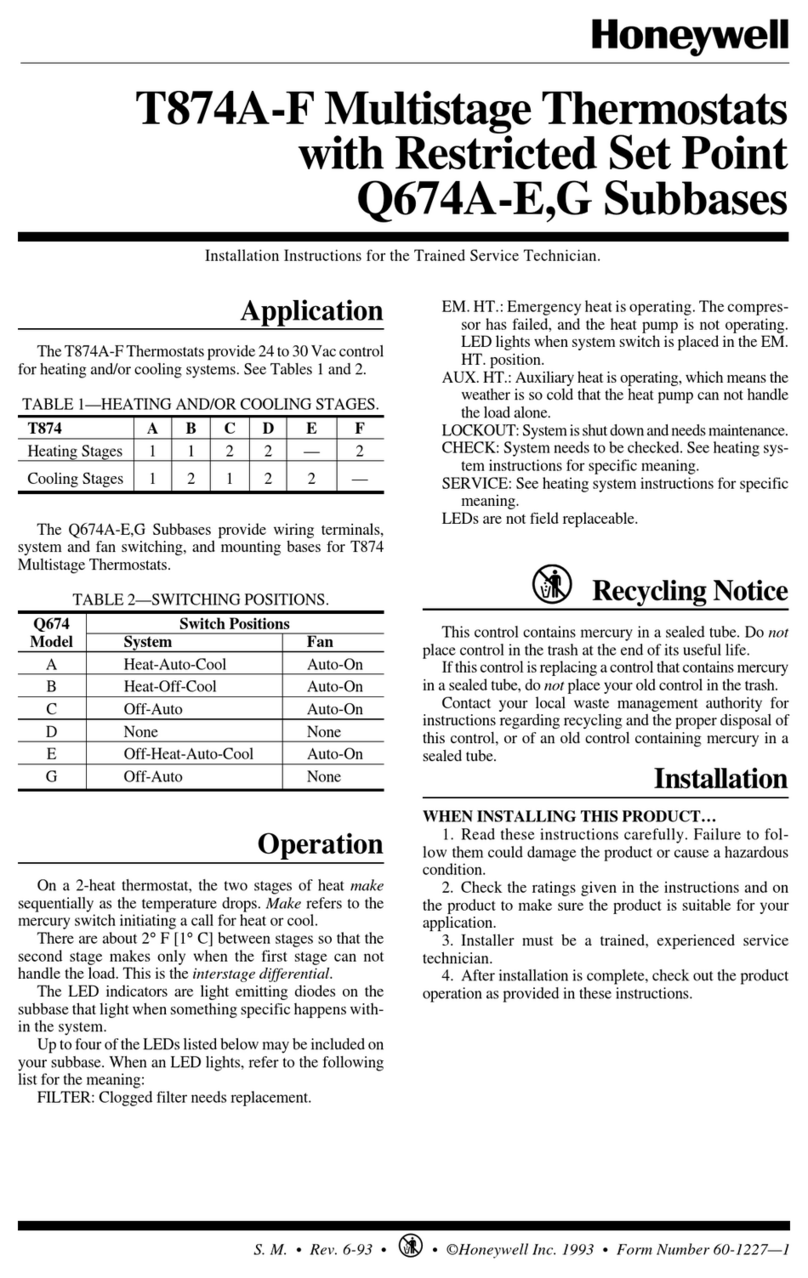
Honeywell Tradeline T874A-F User manual
Honeywell
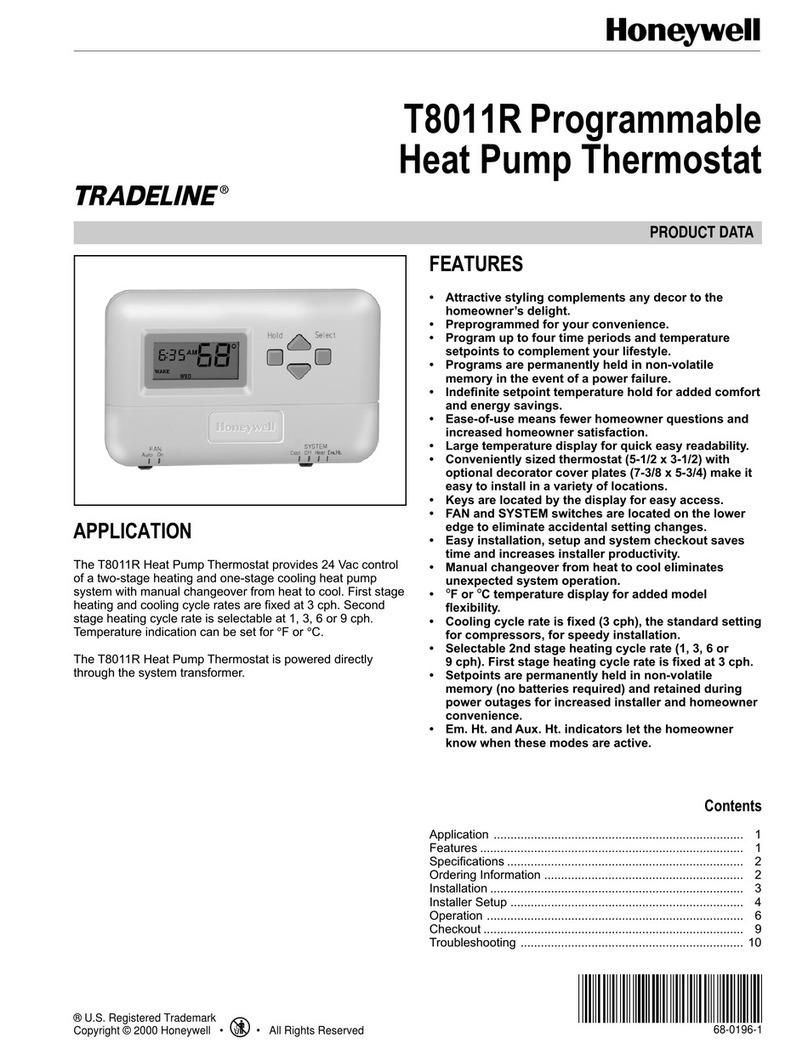
Honeywell TRADELINE T8011R Operation manual
Honeywell
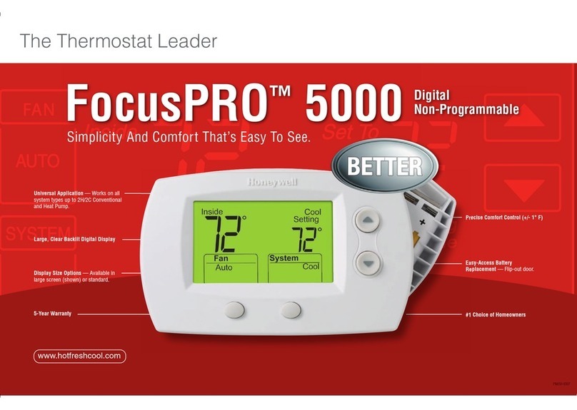
Honeywell FocusPRO 5000 User manual

Honeywell
Honeywell T4398A Operation manual

Honeywell
Honeywell T6811 User manual
Honeywell
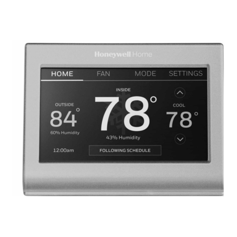
Honeywell RTH9585 Wi-Fi User manual

Honeywell
Honeywell FocusPro TH5320R User manual
Honeywell
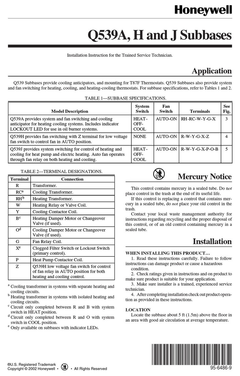
Honeywell Q539A User manual
Honeywell
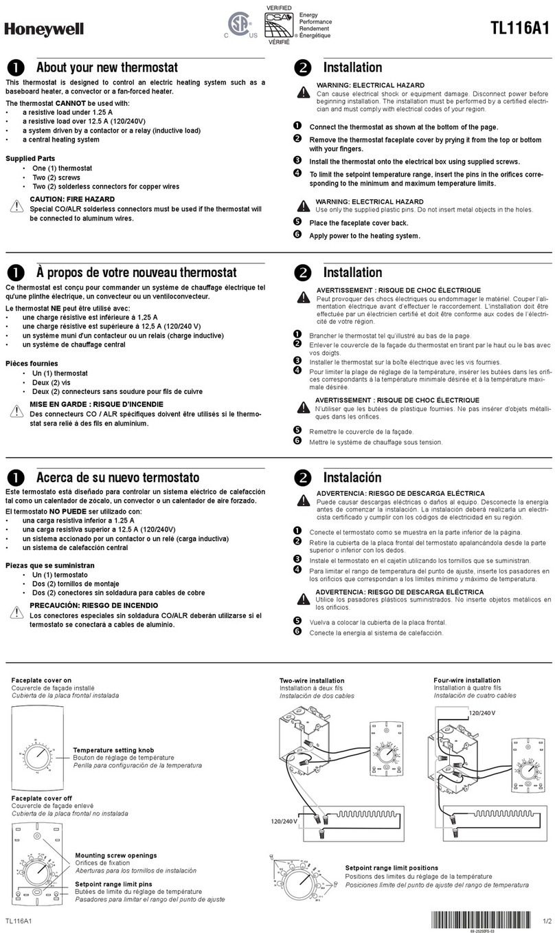
Honeywell TL116A1 User manual
Honeywell
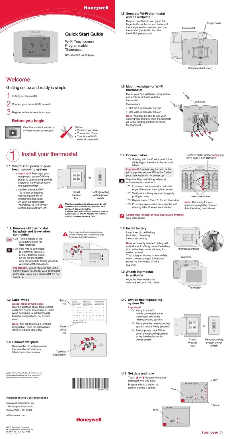
Honeywell RTH8500WF Guide
Honeywell
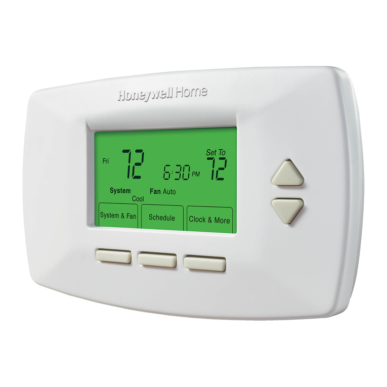
Honeywell RTH7400 series User manual
Honeywell
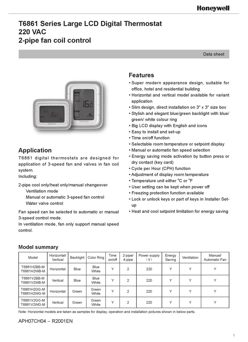
Honeywell T6861 Series Instruction Manual

Honeywell
Honeywell CM701 Installation instructions
Honeywell
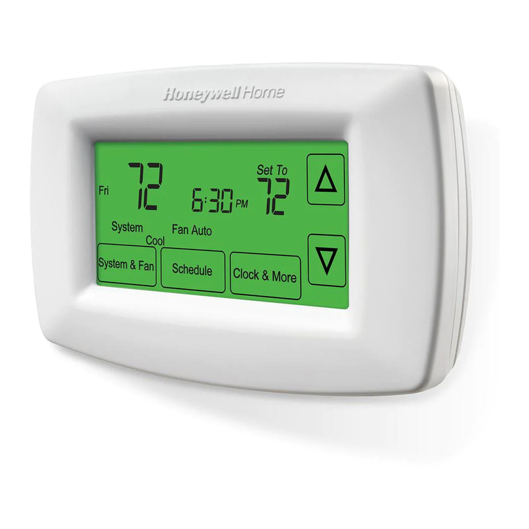
Honeywell RTH7600 Series User manual
Honeywell
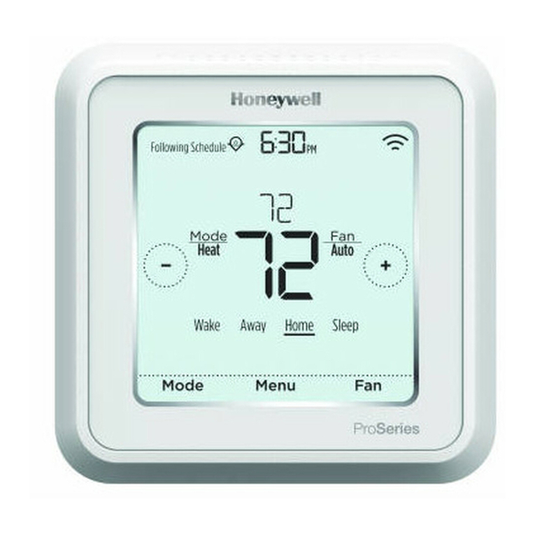
Honeywell Lyric T6 Pro Wi-Fi User manual
Honeywell
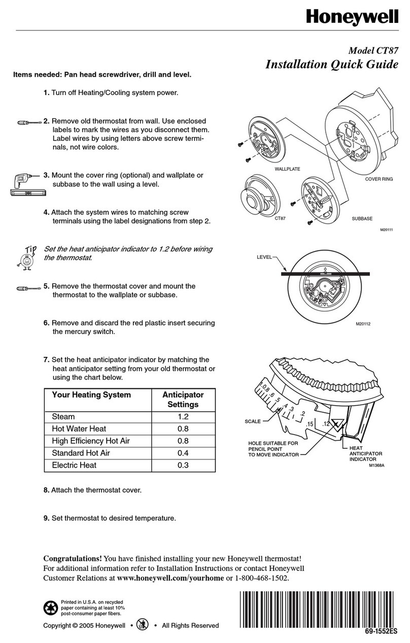
Honeywell CT87 User guide

Honeywell
Honeywell PRO 1000 User manual
Honeywell
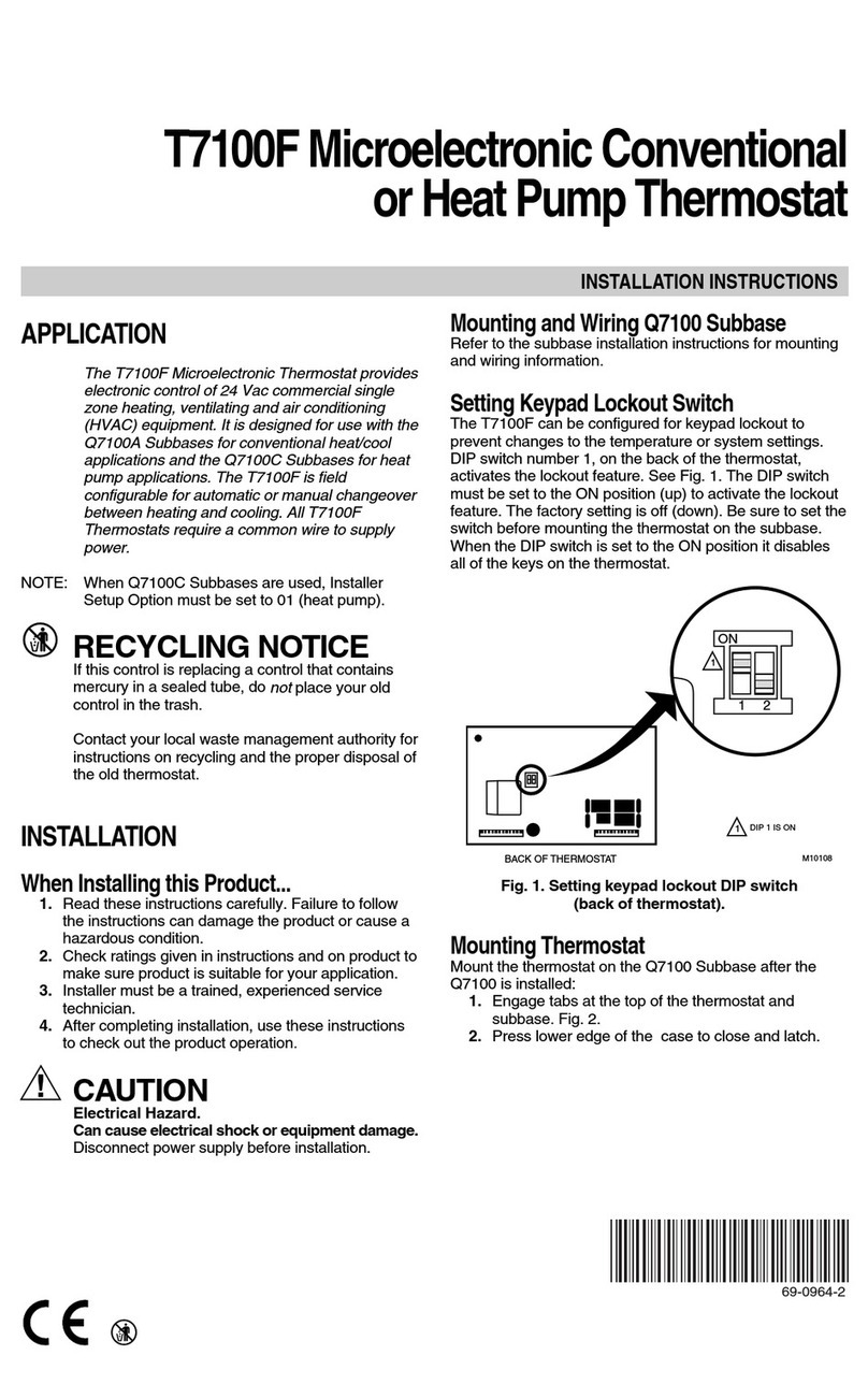
Honeywell t7100f User manual
Honeywell
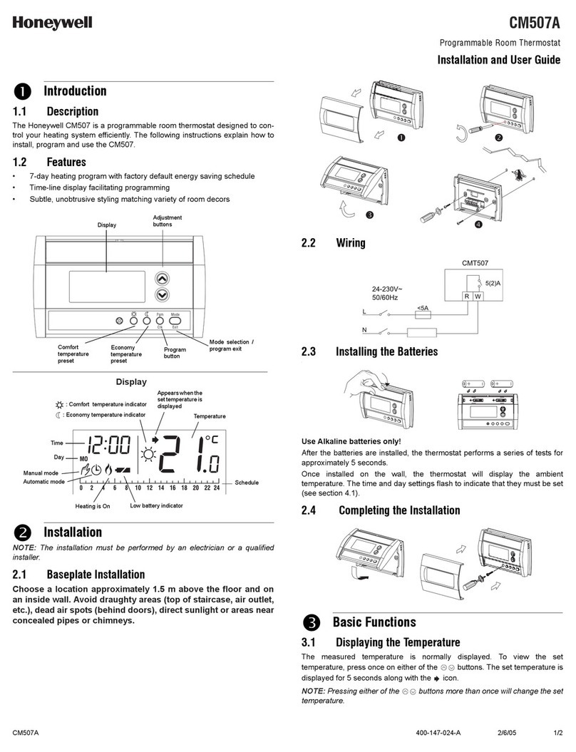
Honeywell CM507A User manual
Honeywell
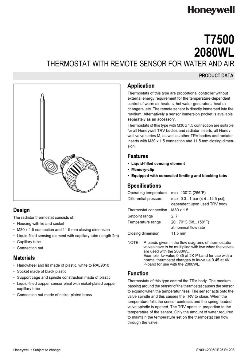
Honeywell 2080WL Operation manual
Popular Thermostat manuals by other brands

NuTone
NuTone NTBZ48 Installation & operation guide

Stelpro
Stelpro MAESTRO ASMT402AD user guide
Aube Technologies
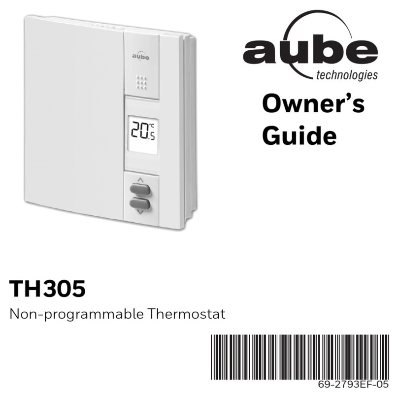
Aube Technologies TH305 owner's guide
Powtier Controls
Powtier Controls 505MST instruction manual
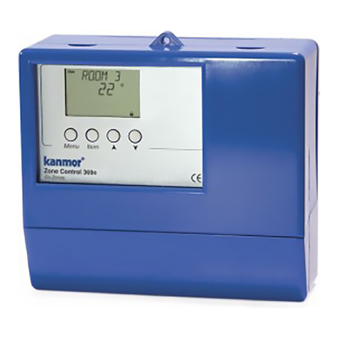
Kanmor
Kanmor Zone Control 369e manual

MICROclimate International
MICROclimate International B2 Magic Eye user guide
