hopf 4490G10 User manual

_____________________________________________________________
Technical Manual
General System Information
Antenna Equipment GPS
ENGLISH
Version: 01.03
-
26.01.2005
_____________________________________________________________
Industriefunkuhren

2 / 34 GPS General System Information - V01.03
hopf Elektronik GmbH
Nottebohmstr. 41
•
D-58511 Lüdenscheid
•
Tel.: +49 (0)2351 9386-86
•
Fax: +49 (0)2351 9386-93
•
Internet: http://www.hopf.com
•
E-Mail: info@hopf.com

INPORTANT NOTES
GPS General System Information - V01.03 3 / 34
hopf Elektronik GmbH
Nottebohmstr. 41
•
D-58511 Lüdenscheid
•
Tel.: +49 (0)2351 9386-86
•
Fax: +49 (0)2351 9386-93
•
Internet: http://www.hopf.com
•
E-Mail: info@hopf.com
Downloading Technical Manuals
All current manuals of our products are available free of charge via our homepage on the
Internet.
Homepage: http://www.hopf.com
E-Mail: inf[email protected]om
Symbols and Characters
Operational Reliability
Disregard may cause damages to persons or material.
Functionality
Disregard may impact function of system/device.
Information
Notes and Information.

SERVICE RELIABILITY
4 / 34 GPS General System Information - V01.03
hopf Elektronik GmbH
Nottebohmstr. 41
•
D-58511 Lüdenscheid
•
Tel.: +49 (0)2351 9386-86
•
Fax: +49 (0)2351 9386-93
•
Internet: http://www.hopf.com
•
E-Mail: info@hopf.com
Safety regulations
The safety regulations and observance of the technical data serve to
ensure trouble-free operation of these devices and protection of persons
and material. It is therefore of utmost importance to observe and
compliance with these regulations.
If these are not complied with, then no claims may be made under the
terms of the warranty and no liability will be assumed for any ensuing
damage.
Safety of the device
These devices has been manufactured in accordance with the latest
technological standards and approved safety regulations
These devices should only be put into operation by trained and qualified
staff. Care must be taken that all cable connections are laid and fixed in
position correctly. The devices should only be operated with the voltage
supply indicated on the identification label.
The devices should only be operated by qualified staff or employees who
have received specific instruction.
If a device must be opened for repair, this should only be carried out by
employees with appropriate qualifications or by hopf Elektronik GmbH.
Before a device is opened or a fuse is changed all power supplies must
be disconnected.
If there are reasons to believe that the operational safety can no longer be
guaranteed the device must be taken out of service and labelled
accordingly.
The safety may be impaired when a device does not operate properly or if
it is obviously damaged.

TABLE OF CONTENTS
GPS General System Information - V01.03 5 / 34
hopf Elektronik GmbH
Nottebohmstr. 41
•
D-58511 Lüdenscheid
•
Tel.: +49 (0)2351 9386-86
•
Fax: +49 (0)2351 9386-93
•
Internet: http://www.hopf.com
•
E-Mail: info@hopf.com
Contents Page
1How GPS works ............................................................................................................7
2Accessories...................................................................................................................8
2.1 GPS Antenna ............................................................................................................8
2.1.1 Where to install the antenna .................................................................................................8
2.1.2 Mechanical Structure of the Antenna....................................................................................8
2.1.3 Electrical Structure of the Antenna .......................................................................................8
2.2 Antenna Cable...........................................................................................................9
2.2.1 Cable Length and Cable Types ............................................................................................9
2.2.2 Preparation of the cable........................................................................................................9
2.2.3 Cable Installation.................................................................................................................10
2.3 Lightning Protection.................................................................................................11
2.3.1 General Information about Lightning Protection .................................................................11
2.3.2 Causes of Overloading .......................................................................................................11
2.3.2.1 Electrostatic Field ....................................................................................................................... 11
2.3.2.2 Increase in the Earth Potential.................................................................................................... 11
2.3.2.3 Electromagnetic Radiation.......................................................................................................... 11
2.3.3 Lightning Protection Concept..............................................................................................12
2.3.3.1 Rough Lightning Protection......................................................................................................... 12
2.3.3.2 Fine Protection (in the hopf GPS receiver board) ..................................................................... 12
2.3.3 Installation .............................................................................................................................12
2.4 Line Amplifier...........................................................................................................13
2.4.1 Installation ...........................................................................................................................13
2.5 Dual Power Splitter (Operation of two Appliances on one Antenna) .......................14
2.5.1 Installation ...........................................................................................................................14
2.5.2 Outside Connection.............................................................................................................14
2.6 8x Power Splitter (Operation of eight Appliances on one Antenna).........................14
3Technical Data ............................................................................................................15

TABLE OF CONTENTS
6 / 34 GPS General System Information - V01.03
hopf Elektronik GmbH
Nottebohmstr. 41
•
D-58511 Lüdenscheid
•
Tel.: +49 (0)2351 9386-86
•
Fax: +49 (0)2351 9386-93
•
Internet: http://www.hopf.com
•
E-Mail: info@hopf.com
4Appendix .....................................................................................................................17
4.1 A01 - World Time Zone Map....................................................................................17
4.2 A02 - Method of Mounting for Outdoor Antennas GPS DCF77 ................................18
4.3 A03 - Mounting of Antenna 4490G10 / 441800A .....................................................19
4.4 A04 - Dimensions of Antenna 4490G10 / 441800A..................................................20
4.5 A04a - Dimensions of Antenna 4490G11 / 441700A................................................21
4.6 A05 - Mounting Bracket for Antenna 4490G10 / 441800A .......................................22
4.7 A06 - GPS Reception in 3D and Position Fixed Mode .............................................23
4.8 A07 - GPS antenna cabling for max. 25m (82 ft) cable ............................................24
4.9 A08 - GPS antenna cabling for max. 100m (328 ft) cable ........................................25
4.10 A09 - GPS antenna cabling for max. 200m (656 ft) cable ........................................26
4.11 A10 - GPS antenna cabling for max. 325m (1066 ft) cable ......................................27
4.12 A11 - GPS antenna cabling for Power Splitter 4443 (Configuration 1) .....................28
4.13 A12 - GPS antenna cabling for Power Splitter 4443 (Configuration 2) .....................29
4.14 A13 - Assembly of RG59 cable................................................................................ 30
4.15 A14 - Assembly of low loss LSZH* cable ................................................................. 31
4.16 A15 - Dimensions of Lightning Protector..................................................................32
4.17 A16 - Dimensions of Line Amplifier..........................................................................33
4.18 A17 - Dimensions of GPS Power Splitter................................................................. 34

HOW GPS WORKS
GPS General System Information - V01.03 7 / 34
hopf Elektronik GmbH
Nottebohmstr. 41
•
D-58511 Lüdenscheid
•
Tel.: +49 (0)2351 9386-86
•
Fax: +49 (0)2351 9386-93
•
Internet: http://www.hopf.com
•
E-Mail: info@hopf.com
1 How GPS works
At a height of about 20,000km satellites circle around the earth twice a day on 6 different
orbits and angles (see picture below).
The GPS system1was developed on the basis of 18 satellites with 3 in reserve. In the
course of time this number was increased to 24 plus 3 in reserve to cover possible short-
term breaks in coverage. Therefore 6 to 11 satellite are visible from any point on earth at all
times. On board each satellite there is a highly accurate atomic clock (accuracy at least 1 x
10-12).
A basic frequency of 10.23 MHz is derived from the frequency of the atomic clocks. The two
carrier frequencies L1 and L2 are produced from this basic frequency.
• transmission frequency L1 = 154 * basic frequency = 1575.42 MHz
• transmission frequency L2 = 120 * basic frequency = 1227.60 MHz
Every satellite broadcasts by modulation all the important navigation and system data on
these two carrier frequencies. The data of the frequency L1 may be decoded for civil
purposes. The exact time can be calculated from these data and the position defined via the
antenna.
The GPS antenna receives signals from all the satellites visible above the horizon and
passes them on to the GPS receiver through a coaxial cable. Four satellites are required for
continuous time decoding.
The GPS world-time UTC2is calculated by subtracting the leap seconds from the GPS
world-time (GPS-UTC). At present (JAN 1999) world-time lags 13 seconds behind GPS-
UTC. The difference is not constant, but changes with every insertion of a leap second.
1GPS = Global Positioning System
2UTC = Universal Time Coordinated

ACCESSORIES
8 / 34 GPS General System Information - V01.03
hopf Elektronik GmbH
Nottebohmstr. 41
•
D-58511 Lüdenscheid
•
Tel.: +49 (0)2351 9386-86
•
Fax: +49 (0)2351 9386-93
•
Internet: http://www.hopf.com
•
E-Mail: info@hopf.com
2 Accessories
2.1 GPS Antenna
Due to the small signal level an outdoor installation of the antenna is recommended.
2.1.1 Where to install the antenna
Since the antenna is designed to receive data from all directions it must be non-directional.
Because of the high frequency there must be "visual contact" to the satellites.
Visual contact means that no solid or large objects (buildings) may block the view to the
horizon (see drawing A06 "GPS Reception in 3D and Position Fixed Mode"). Rain, fog and
clouds as well as small objects, e.g. chimneys, at a certain distance may impair the view
minimally.
The larger the visible section of the sky, the longer the post-connected
electronics remain radio-synchronous.
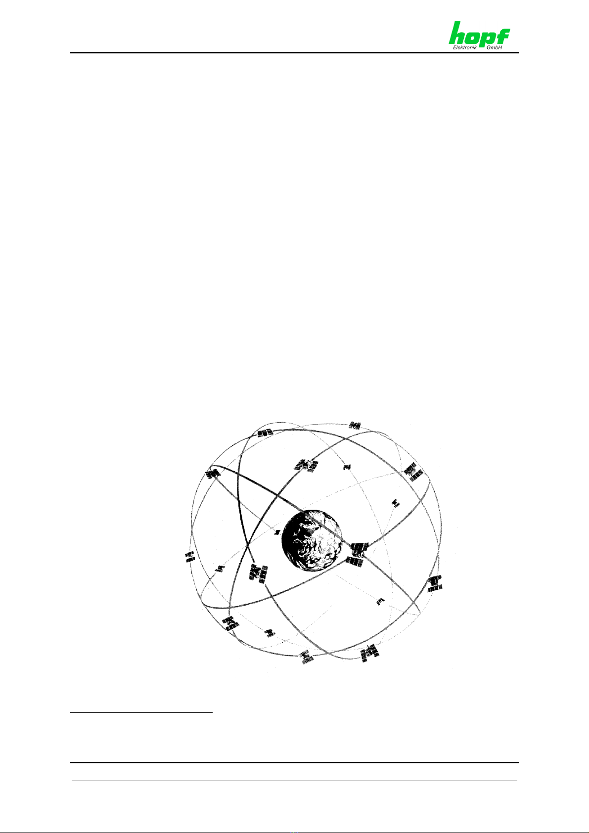
In the standard reception mode (3D) of the GPS system reception from at least 4 satellites is
necessary. In position fixed mode reception from only one satellite is necessary (see
technical description of GPS system). It is also possible to install the antenna behind a non-
coated window.
No additional voltage supply is required to operate the antenna. It is provided via the
antenna cable and is supplied by the BNC connector of the hopf GPS system.
2.1.2 Mechanical Structure of the Antenna
The antenna is housed in a round weatherproof plastic casing. The casing cover is arched to
prevent any rain water, snow or other impurities from settling on the antenna.
The mechanical construction (see drawing A04 "Dimensions of Antenna 4490G10 / 4418A")
consists of sturdy, anodized aluminium or aluminium die-casting and is designed to resist
high winds.
The plastic housing can be installed horizontally as well as vertically to the mechanical parts
(see drawing A03 "Mounting of Antenna 4490G10 / 4418A"), allowing both wall and flat-roof
installation of the antenna. The antenna cable can be fed either through the base or through
a slot on the side of the mounting flange.
2.1.3 Electrical Structure of the Antenna
As the antenna is non-directional, reception cannot be improved by mechanical shaping as,
for example, with parabolic antennas. Therefore the signal strength at the antenna input is
about 1 x 10-16 Watts and already below the generally permitted noise level.
An extremely low-noise pre-amplifier is placed behind the antenna in order to feed the
signals to the electronics via an antenna cable. The antenna cable also supplies the voltage
to the pre-amplifier.

ACCESSORIES
GPS General System Information - V01.03 9 / 34
hopf Elektronik GmbH
Nottebohmstr. 41
•
D-58511 Lüdenscheid
•
Tel.: +49 (0)2351 9386-86
•
Fax: +49 (0)2351 9386-93
•
Internet: http://www.hopf.com
•
E-Mail: info@hopf.com
2.2 Antenna Cable
2.2.1 Cable Length and Cable Types
The cable length is restricted because of the high frequency and the low signal strength. It
can be lengthened by using a repeater. At present two different types of cables are available
allowing the following distances between antenna and electronics to be bridged:
• Cable length up to max. 25 m (82.0 ft): Using standard cable ring KA4017
• Cable length over 25 m (82.0 ft): Using hopf LSZH cable KA110109
The combination of different cable types within one antenna configuration is
not possible.
hopf low loss LSZH1cable KA110109 replaces hopf GPS special cable KA110107. The
BNC connectors ST001106 used for hopf GPS special cable KA110107 are also suitable
for the new hopf low loss LSZH cable KA110109.
Antenna cable length see
Standard cable RG59, supplied on a coil: max. 25 m (82.0 ft) (A07)
hopf low loss LSZH cable without line-amplifier 6849: max. 100 m (328.0 ft) (A08)
hopf low loss LSZH cable with one line-amplifier 6849: max. 200 m (656.0 ft) (A09)
hopf low loss LSZH cable with two line-amplifiers
6849:
max. 325 m
(1,066.0 ft)
(A10)
hopf low loss LSZH Kabel without line-amplifier 6849
with power splitter 4443 (Configuration 1):
max. 75 m (A11)
hopf low loss LSZH Kabel without line-amplifier 6849
with power splitter 4443 (Configuration 2):
max. 75 m (A12)
A maximum of two line amplifiers can be used.
For antenna systems deviating from the above-listed configurations (e.g.
modules and cable lengths) clarification based on the required cable length
is necessary.
2.2.2 Preparation of the cable
Because of the high frequency and the signals below the permitted noise level, special
attention must be paid to preparation of the cable. If the cables are not prepared correctly
this could impair reception.
When antenna systems are ordered with cables prepared by hopf the whole system is
factory-tested for reception.
For preparation of the antenna cable by the customer refer to: A13-A14.
1LSZH: Low Smoke Zero Halogen

ACCESSORIES
10 / 34 GPS General System Information - V01.03
hopf Elektronik GmbH
Nottebohmstr. 41
•
D-58511 Lüdenscheid
•
Tel.: +49 (0)2351 9386-86
•
Fax: +49 (0)2351 9386-93
•
Internet: http://www.hopf.com
•
E-Mail: info@hopf.com
2.2.3 Cable Installation
When laying the cable special attention must be paid to the following points:
• The coaxial connectors should not be damaged or soiled. The connections should
be protected with plastic foil.
• The bending radius of the cable must not be less than 50 mm.
• No section of the cable should be squeezed nor should the insulation coating be
damaged
The cable is fed through the antenna base and connected to the antenna via a coaxial
connector. To lay the cables this can be disconnected. To do this the Allan screws on the
antenna base are removed and the dish is lifted off.
The cable must not be installed in the vicinity of other HF-, control or power
cables.
The emitted radio interference from these cables may interfere with GPS reception because
of the extremely low reception power.

ACCESSORIES
GPS General System Information - V01.03 11 / 34
hopf Elektronik GmbH
Nottebohmstr. 41
•
D-58511 Lüdenscheid
•
Tel.: +49 (0)2351 9386-86
•
Fax: +49 (0)2351 9386-93
•
Internet: http://www.hopf.com
•
E-Mail: info@hopf.com
2.3 Lightning Protection
2.3.1 General Information about Lightning Protection
When outdoor antennas are used high interference voltage or current pulses may occur in
the antenna cable during thunderstorms. This may result in damaging or destroying not only
the directly connected radio-controlled clock system but also any other devices connected.
To avoid severe damage and damage-related costs an indirect lightning protection should be
installed between the outdoor antenna and the circuit board of the radio-controlled clock (see
drawing A15 "Dimensions of Lightning Protector").
2.3.2 Causes of Overloading
Buildings can be protected with the aid of the lightning conductor developed by Benjamin
Franklin. This though does not, however, protect the electronic devices inside from indirect
consequences of lightning.
A flash of lightning is simply an excessive short circuit of two lines with different potentials.
When lightning occurs these two lines are usually two layers of cloud or one layer of cloud
and the earth. Then a current of 1000 to 100000 ampere circulates between the two layers of
cloud or between the earth and the clouds. On unprotected devices connected to open lines
(antenna, antenna cable) this results in the following forms of indirect interference or
destructive influence.
2.3.2.1 Electrostatic Field
The increase of the electrostatic field up to 50 kV/m can be caused by the vicinity of
potential-loaded thunder clouds or by the static charging of the air. Field changes take place
suddenly creating high-frequency, electromagnetic micro-pulses.
2.3.2.2 Increase in the Earth Potential
When lightning strikes into the ground this causes a sudden increase in the earth potential
which depends on the power of the current and on the local specific resistance of the earth.
This overloading is reduced undulatorily through the ground and this causes high voltage-
potential differences in unprotected devices.
2.3.2.3 Electromagnetic Radiation
The flash of lightning may be compared to an antenna of several kilometres length. The
pulse current of several kiloamperes radiates a strong electromagnetic field. This radiation
induces high voltages and currents in "neighbouring" lines (1 to 2 km) which can also cause
overloading in connected devices.

ACCESSORIES
12 / 34 GPS General System Information - V01.03
hopf Elektronik GmbH
Nottebohmstr. 41
•
D-58511 Lüdenscheid
•
Tel.: +49 (0)2351 9386-86
•
Fax: +49 (0)2351 9386-93
•
Internet: http://www.hopf.com
•
E-Mail: info@hopf.com
2.3.3 Lightning Protection Concept
Overloading caused by the indirect effects of lightning cannot be avoided, but devices can be
protected against its destructive consequences.
To reduce overloading as quickly as possible it is necessary to short-circuit the lines. When
the problem is solved the device should return to its original specifications.
This is why the hopf lightning strategy is made up of a combination of rough and fine
protection.
2.3.3.1 Rough Lightning Protection
The double-chamber gas arrestor, located in the lightning protection, has a dynamic
operating voltage of < 700 V and conducts voltage, when ignited, out of the cable to the
earth potential.
2.3.3.2 Fine Protection (in the hopf GPS receiver board)
Fast absorber diodes with a response time of < 1 nsec. and an absorber power of 600 W at
the input of the GPS receiver board keep the potential differences between antenna core
and zero at a constant approximate ±6 V until ignition of the double-chamber gas arrestor.
Because of the high frequency and the signals below the permitted noise level, the elements
must be set up in strip-line sequence.
This combination also guarantees the potential separation of the antenna circuit to other
electronics in conditions without interference.
If no further devices (eg. power splitter) are installed between lightning
protection and electronic with fine protection, for safety reasons a maximum
cable length must not be exceeded (see also drawings of cable
configuration A07 - A10 in the appendix of this description).
2.3.3 Installation
When hopf lightning protection is used it is assumed that at the location there is a
comprehensive lightning protection concept, including direct lightning protection of the
building according to VDE and a lightning-protected voltage supply to the devices.
The antenna is connected to the "Antenna / Antenne" BNC connector, and the extended
cable to the electronics on the connector marked "Receiver / Empfänger".
It is important that the earth line of the connected device has the same earth connection
point as the lightning protection, so that no destructive potential differences can arise.
Earth wire:
The earth wire may not exceed a maximum length (see also drawing A02 "Method of
Mounting for Outdoor Antennas GPS / DCF77" in the appendix of this description).
Only trained personnel may install the lightning protection.

ACCESSORIES
GPS General System Information - V01.03 13 / 34
hopf Elektronik GmbH
Nottebohmstr. 41
•
D-58511 Lüdenscheid
•
Tel.: +49 (0)2351 9386-86
•
Fax: +49 (0)2351 9386-93
•
Internet: http://www.hopf.com
•
E-Mail: info@hopf.com
2.4 Line Amplifier
For positioning and required quantity of line amplifiers see Appendix A09-A10.
2.4.1 Installation
The line amplifier (see drawing A16 "Dimensions of Line Amplifier") is integrated into an HF-
proof housing with a base plate. It is therefore easy to fix the device to the wall.
Refer to chapter 2.2.1 Cable Length to find out for which lengths of cable it is necessary to
use the 6849 line amplifier.
The 6849 line amplifier is looped into the antenna cable. The voltage supply of the
line amplifier is provided via the antenna cable by the BNC connector of the hopf GPS
system.
The GPS antenna cable from the antenna is connected to the BNC connector "ANTENNA".
The signal is supplied to the connected hopf GPS system by the BNC connector
"RECEIVER".
To avoid destruction caused by overloading ensure that the line amplifier is
not earthed.
The integrated fine protection of the line amplifier enables installation before the lightning
protection without any risk of destroying the line amplifier through overloading.

ACCESSORIES
14 / 34 GPS General System Information - V01.03
hopf Elektronik GmbH
Nottebohmstr. 41
•
D-58511 Lüdenscheid
•
Tel.: +49 (0)2351 9386-86
•
Fax: +49 (0)2351 9386-93
•
Internet: http://www.hopf.com
•
E-Mail: info@hopf.com
2.5 Dual Power Splitter
(Operation of two Appliances on one Antenna)
The passive Power Splitter 4443 is used to separate the antenna signal into two equally
strong signals to minimize the loss while operating two hopf GPS systems on one antenna.
The power splitter also serves to decouple the external voltage supply on the internal
conductor of the antenna.
2.5.1 Installation
The Power Splitter (see drawing A17 "Dimensions of GPS Power Splitter") is mounted in a
HF-proof housing with an insulated base plate. The unit can therefore be easily screwed to
the wall near the GPS systems. The antenna is connected to the single BNC-connector
called "Antenna in". On the opposite side of the housing there are the two antenna outputs
to the GPS systems.
The voltage supply of the power splitter is provided via the antenna cable and is supplied by
the "GPS in" BNC connector of the hopf GPS system.
The power splitter may not connected to earth to avoid damage by
overvoltage.
The integrated fine protection of the power splitter enables installation before the lightning
protection without any risk of destroying the power splitter through overloading.
A free output port should be closed with a HF resistor of 50 Ω.
2.5.2 Outside Connection
It is also possible to connect a foreign GPS-system to a free splitter output. Care must be
taken that the external power supply of the alien device for the antenna lies within the
permitted voltage range (refer to technical data). The outside device must also be able to
evaluate the original GPS signal in the L1 band.
2.6 8x Power Splitter
(Operation of eight Appliances on one Antenna)
Also an 8x power splitter is disposable by the hopf company.
Take contact to us to get more information about this power splitter .

TECHNICAL DATA
GPS General System Information - V01.03 15 / 34
hopf Elektronik GmbH
Nottebohmstr. 41
•
D-58511 Lüdenscheid
•
Tel.: +49 (0)2351 9386-86
•
Fax: +49 (0)2351 9386-93
•
Internet: http://www.hopf.com
•
E-Mail: info@hopf.com
3 Technical Data
Antenna 4490
Type of antenna: micro-strip-line with pre-amplifier
Mean frequency: 1575.42 MHz
Band width: 10 MHz
Angle of view: + 10° above the horizon
Impedance: 50 Ohm
Power amplification: 20 dB
Voltage supply via the antenna cable: 4.5 - 7V DC
Temperature range:
• Operation:
• Storage:
-30° C to +85° C
-40° C to +85° C
Humidity: 100%
Protection class: IP65
Category of application outdoors
MTBF: > 500,000 h1
Lightning Protection 4495
Housing: aluminium die-cast housing
Dimensions of housing: 250 x 105 x 95 mm
Input / output: BNC-connector
Earth connection point: screw connection M6
Weight: approx. 1.8 kg
Operating speed: < 1ns
Current surge pulse 8/20 µs wave form: 10 kA
Protection level at 6 kV 1,5/50 µsec. wave
at input:
< 12 V
Input impedance: 50 Ω
Insertion loss: max. 3 dB
Temperature range:
• Operation:
• Storage:
-20° C to +80° C
-40° C to +85° C
Humidity: 95% not condensed
Protection class: IP40
Category of Application indoors, protected
MTBF: > 10,000,000 h2
Outdoor antennae and lightning protection can be destroyed by lightning.
We can therefore provide only a limited guarantee for these parts.
1Equipment may be damaged by lightning - mentioned values are only theoretical values.
2Lightning protector excluded guarantee.

TECHNICAL DATA
16 / 34 GPS General System Information - V01.03
hopf Elektronik GmbH
Nottebohmstr. 41
•
D-58511 Lüdenscheid
•
Tel.: +49 (0)2351 9386-86
•
Fax: +49 (0)2351 9386-93
•
Internet: http://www.hopf.com
•
E-Mail: info@hopf.com
Line Amplifier 6849
Impedance: input / output 50 Ω
Frequency range: 1575 MHz
Band width: ± 50 MHz
Power amplification: min. 20 dB
Voltage supply via the antenna cable: 4.5 - 7V DC
Weight: approx. 0.13 kg
(1.8 kg with protection housing)
Temperature range:
• Operating:
• Storage:
-20° C to +80°C
-40° C to +85° C
Humidity: 95% not condensed
Protection class: IP50
Category of application indoors, protected
MTBF: > 10,000,000 h
Power Splitter 4443
Operating frequency: 1575 MHz
Insertion loss (S21, S31): max. 1 dB
Input reflection damping (S11): 22 - 26 dB
Output reflection attenuation (S22,S33): 20 - 26 dB
Output insulation (S23): 23 - 27 dB
Amplitude stability (output): 0.05 - 0.15 dB
VSWR (input): min. 1 : 1.17 dB
External current: max. 50 mA
Temperature range:
• Operating:
• Storage:
-20° C to +80° C
-40° C to +85° C
Humidity: 95% not condensed
Protection class: IP50
Category of application: indoors, protected
MTBF: > 10,000,000 h

post box 1847
D-58468 Lüdenscheid
fon: (02351) 938686
fax: (02351) 459590
name
check
date
size
page
System
date changes name
changes drawing number
Elektronik GmbH
World Time Zone Map (Difference Time to UTC)
Unterteilung der Zeitzonen (Differenzzeit zu UTC)
Vollmer
11.09.01
A4
ZC01091101
World Time Zone Map
(Difference Time to UTC)
Universal Time Coordinated
formely
Greenwich Mean Time
(UTC)
(GMT)
(vormals)
WEST EAST
Subtract time zone number from local time to
obtain UTC. Add time zone number to UTC
to obtain local time.
(Subtrahiere Zeitzonen-nr. von lokaler Zeit um UTC
zu erhalten. Addiere Zeitzonen-nr. zu UTC um lokale
Zeit zu erhalten).
Add time zone number to local time to obtain
UTC. Subtract time zone number from UTC
to obtain local time.
(Addiere Zeitzonen-nr. zu lokaler Zeit um UTC zu
erhalten. Subtrahiere Zeitzonen-nr. von UTC um
lokale Zeit zu erhalten.)
10:00
2
09:00
3
08:00
4
07:00
5
06:00
6
05:00
7
04:00
8
11:00
1
13:00
1
14:00
2
15:00
3
16:00
4
17:00
5
18:00
6
19:00
7
20:00
8
21:00
9
22:00
10
23:00
11
03:00
9
02:00
10
Sun
01:00
11
Sun Sun
24:00
12
12:00
0
Sat
24:00
12
01
11
Number indicates standard time in zone when it is 12 noon, UTC
(Nummer gibt die Standardzeit der Zone an wenn es 12 Uhr UTC ist)
- A01 -

name
check
date
size
page
System
date changes name
changes drawing number
post box 1847
D-58468 Lüdenscheid
tel.: +49 (0)2351 938686
fax: +49 (0)2351 938693
Elektronik GmbH
cable entry
Hauseinführung
4490G10 / 441800A
EARTH STRAP (braided):
10 mm² (0.0155 inch²)
for max. d=10m (32.8 ft)
4 mm² (0.0062 inch²)
for max. d=2.5m (8.2 ft)
Erdleitung
4490G10 / 441800A
4490G10 / 441800A
4490G12 / 4420004490G12 / 442000
4490G10 / 441800A4490G10 / 441800A
4490G11 / 441700A4490G11 / 441700A
pole mounting not included
Mastbefestigung nicht im
Lieferumfang enthalten
antenna cable
Method of Mounting for Outdoor Antennas GPS DCF77/
/Montagearten Außenantennen GPS DCF77
tvo
20.05.05
A4
02247 1/1
Method of Mounting for
Outdoor Antennas GPS / DCF77
- A02 -

name
check
date
size
page
System
date changes name
changes drawing number
post box 1847
D-58468 Lüdenscheid
tel.: +49 (0)2351 938686
fax: +49 (0)2351 938693
Elektronik GmbH
tvo
24.09.02
A4
02036a
vertical wall
Senkrechte Hauswand
flat roof
Flachdach
cross-head
Kreuzkopf
cross-head
Kreuzkopf
The tube with the
antenna will be
supplied
unmountedly. The
cross-head will be
pluged according to
mounting for wall or
flat roof.
Das Rohr mit dem
Antennenteller wird
unmontiert geliefert.
Der Kreuzkopf wird je
nach Motagebedarf für
Hauswand oder
Flachdach gesteckt.
Mounting of Antenna 4490G10 441800A/
Montage Antennen 4490G10 441800A/
Mounting of Antenna 4490G10 / 441800A
20.05.05 Bezeichnung tvo
- A03 -

post box 1847
D-58468 Lüdenscheid
fon: (02351) 938686
fax: (02351) 459590
name
check
date
size
page
System
date changes name
changes drawing number
Elektronik GmbH
Vollmer
16.09.02
A4
02030
All dimensions in mm (inch)
Dimensions of Antenna 4490G10 441800A/
Abmessungen Antennen 4490G10 441800A/
52,0 (2.05”)
Screw M8 for earth connection
(Schraube M8 für Erdleitung)
Allen Screw M8
(Inbusschraube)
45,0 (1.77”)
290,0 (11.42”)
84,0 (3.31”)
. 40,0 (1.57”)
Ø 149,6 (5.89”)
50,0 (1.97”)
Dimension of Antenna 4490G10 / 441800A
1)
1)
2)
2)
1)
1)
Tube (Rohr)
Ø 30 (1.18") x 210 (8.27")
Material:
1) Aluminium
2) Plastic / Kunststoff
- A04 -
This manual suits for next models
2
Table of contents
Popular Antenna manuals by other brands

PNI
PNI Duplex 2000 user manual

Comba Telecom
Comba Telecom MRU-4500 user manual

TRENDnet
TRENDnet TEW-AI75OB - 11a/g 7/5dBi Indoor Omni Directional... Specifications

Shakespeare Electronic
Shakespeare Electronic Galaxy Style 5310-R installation instructions

Amped Wireless
Amped Wireless WA Setup guide

Motorola
Motorola PMAN5100 installation manual