manuals.online logo
Brands
  1. Home
  2. •
  3. Brands
  4. •
  5. Meinberg
  6. •
  7. Antenna
  8. •
  9. Meinberg GPS Antenna User manual

Meinberg GPS Antenna User manual

MANUAL
GPS Antenna
Antenna / Converter Unit
24th January 2011
Meinberg Radio Clocks GmbH & Co. KG
Page 0
Table of Contents
1 Meinberg GPS Antenna/Converter Unit 1
1.1 MountingtheGPSAntenna...................................... 3
1.1.1 Example:............................................ 3
1.1.2 Antenna Short-Circuit Assembly with surge voltage protection . . . . . . . . . . . . . . . 4
1.1.3 AntennaShort-Circuit..................................... 5
1.2 P-TRON: Surge Voltage Protector . . . . . . . . . . . . . . . . . . . . . . . . . . . . . . . . . . 5
1.3 FeaturesofGOAL........................................... 6
0
Date: 2010-08-13 GPS Antenna
Page 1
1 Meinberg GPS Antenna/Converter Unit
- Antenna/Converter Unit
- Preformed Cable
- Holder for Wall Mounting
- Clamps for Pole Mounting
- Optional: Voltage Protector
Antenna: Antenna/converter unit with remote power supply
Length of cable: Refer to chapter "Mounting the Antenna"
Antenna
Input GPS: Antenna circuit 1000 V DC insulated
Receiver Input
Frequency: 1575.42 MHz (L1)
Local Oscillator
to Converter
Frequency: 10 MHz
1
First IF
Frequency: 35.4 MHz
1
Connector: female type-N
Protection
Class: IP66
Ambient
Temperature: -40
◦
C ... +65
◦
C
Weigth: 420g (without accessories)
(1)
these frequencys are transfered via the antenna cable.
Power Requirements: 12V ... 18V, 100mA (via antenna cable)
GPS Antenna Date: 2010-08-13
1
Page 2 1 Meinberg GPS Antenna/Converter Unit
Physical Dimensions:
4444
240240
140140
450450
7070
M6M6
180180
6868
8484
66
2
Date: 2010-08-13 GPS Antenna
1.1 Mounting the GPS Antenna Page 3
1.1 Mounting the GPS Antenna
The GPS satellites are not stationary, but circle round the globe with a period of about 12 hours. They can only
be received if no building is in the line-of-sight from the antenna to the satellite, so the antenna/downconverter
unit must be installed in a location that has as clear a view of the sky as possible. The best reception is achieved
when the antenna has a free view of 8
◦
angular elevation above the horizon. If this is not possible, the antenna
should be installed with the clearest free view to the equator, because the satellite orbits are located between
latitudes 55
◦
North and 55
◦
South. If this is not possible, you may experience diculty receiving the four satellites
necessary to complete the receiver's position solution.
The antenna/converter unit can be mounted on a wall, or on a pole up to 60 mm in diameter. A 50 cm
plastic tube, two wall-mount brackets, and clamps for pole mounting are included. A standard RG58 coaxial
cable should be used to connect the antenna/downconverter unit to the receiver. The maximum length of cable
between antenna and receiver depends on the attenuation factor of the coaxial cable.
Up to four receivers can be run with one antenna/downconverter unit by using an optional antenna splitter.
The total length of an antenna line from antenna to receiver must not be longer than the max. length shown in
the table below. The position of the splitter in the antenna line does not matter.
High voltage protectors must be installed directly after reaching the indoors. The optional delivered protec-
tion kit is not for outdoor usage.
1.1.1 Example:
Type of cable diameter Ø Attenuation at 100MHz max lenght.
[mm] [dB]/100m [m]
RG58/CU 5mm 17 300
(1)
RG213 10.5mm 7 700
(1)
(1)This specications are made for antenna/converter units produced after January, 2005
The values are typically ones; the exact ones are to nd out from the data sheet of the used cable
GPS Antenna Date: 2010-08-13
3
Page 4 1 Meinberg GPS Antenna/Converter Unit
1.1.2 Antenna Short-Circuit Assembly with surge voltage protection
Optional a surge voltage protector for coaxial lines is available. The shield has to be connected to earth as short
as possible by using the included mounting bracket. Standard you connect the antenna converter directly with
the antenna cable to the system.
free view to the sky!
Type N / BNC
male
Type N
female
Type N
female
Surge Voltage Protector
connect to earth by using the mounting bracket.
Type N
male
GPS
Antenna
Meinberg
GPS
s
S
a
t
P
elli
G
te ante
n
a
n
As short as possible!
cable slot
Ground lead to PE Rail
(Protective Earth)
- fastened
with cable shoe
2
Cable / 16mm
4
Date: 2010-08-13 GPS Antenna
1.2 P-TRON: Surge Voltage Protector Page 5
1.1.3 Antenna Short-Circuit
(optional for displayed systems)
In case of an antenna line short-circuit the following message appears in the display:
ANTENNA
SHORT-CIRCUIT
DISCONNECT POWER
! ! !
If this message appears the clock has to be disconnected from the mains and the defect eliminated. After that
the clock can be powered-up again. The antenna supply voltage must be 15V
DC
.
1.2 P-TRON: Surge Voltage Protector
Attachment plug with replaceable gas discharge tube
for coaxial signal interfaces.
Connection: N connector female/female.
The surge voltage protector for coaxial lines has to be installed in the antenna line. The shield has to be con-
nected to earth as short as possible by using the included mounting bracket. It is equipped with two type-N
female connectors.
Key Features
- Surge Voltage Protector for coaxial Lines
- Easy mounting
Nominal discharge
surgecurrent 50kA / Isn(8/20)
µ
s
Multiple strike capability: 20kA 10 times
Response Time 100ns max.
Features Replacable gas discharge tube
Waterproof
Protection voltage: 90V
Scope of supply Surge voltage protector and mounting bracket
(This product is fully RoHS compliant)
GPS Antenna Date: 2010-08-13
5
Page 6 1 Meinberg GPS Antenna/Converter Unit
1.3 Features of GOAL
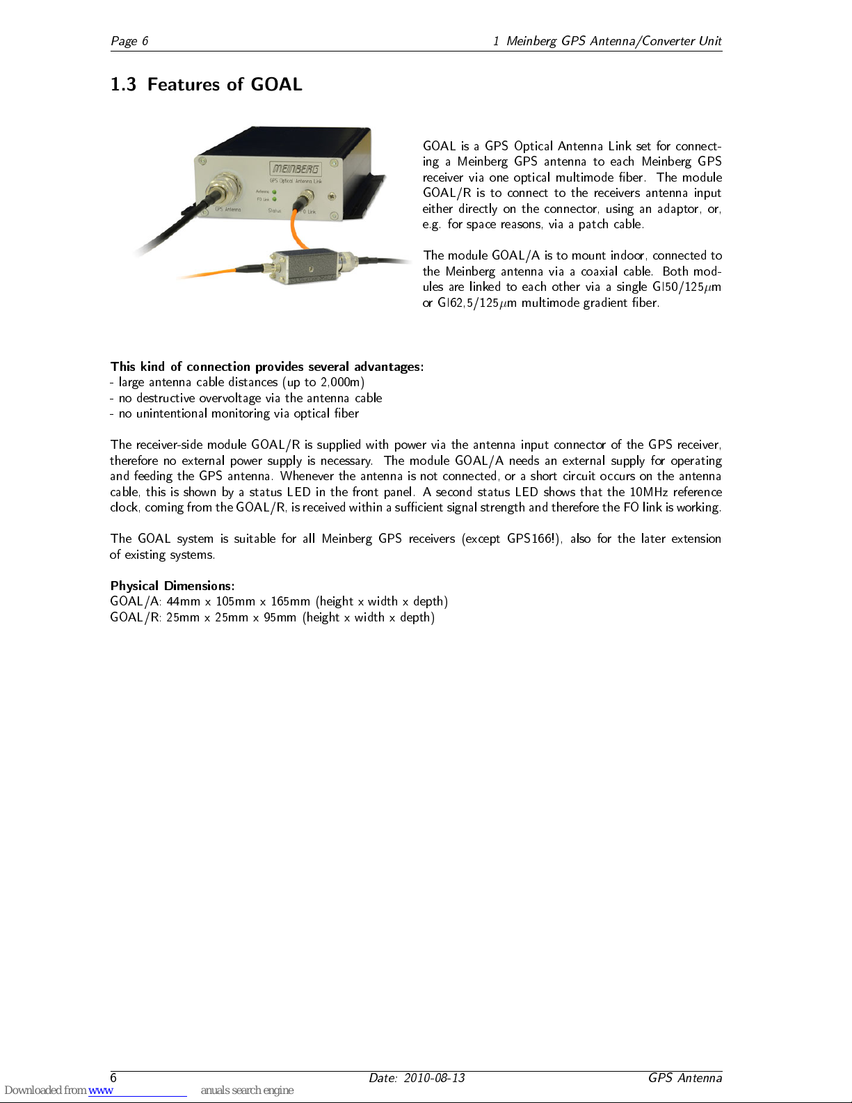
GOAL is a GPS Optical Antenna Link set for connect-
ing a Meinberg GPS antenna to each Meinberg GPS
receiver via one optical multimode ber. The module
GOAL/R is to connect to the receivers antenna input
either directly on the connector, using an adaptor, or,
e.g. for space reasons, via a patch cable.
The module GOAL/A is to mount indoor, connected to
the Meinberg antenna via a coaxial cable. Both mod-
ules are linked to each other via a single GI50/125
µ
m
or GI62,5/125
µ
m multimode gradient ber.
This kind of connection provides several advantages:
- large antenna cable distances (up to 2,000m)
- no destructive overvoltage via the antenna cable
- no unintentional monitoring via optical ber
The receiver-side module GOAL/R is supplied with power via the antenna input connector of the GPS receiver,
therefore no external power supply is necessary. The module GOAL/A needs an external supply for operating
and feeding the GPS antenna. Whenever the antenna is not connected, or a short circuit occurs on the antenna
cable, this is shown by a status LED in the front panel. A second status LED shows that the 10MHz reference
clock, coming from the GOAL/R, is received within a sucient signal strength and therefore the FO link is working.
The GOAL system is suitable for all Meinberg GPS receivers (except GPS166!), also for the later extension
of existing systems.
Physical Dimensions:
GOAL/A: 44mm x 105mm x 165mm (height x width x depth)
GOAL/R: 25mm x 25mm x 95mm (height x width x depth)
6
Date: 2010-08-13 GPS Antenna
Konformitätserklärung
Declaration of Conformity
Hersteller Meinberg Funkuhren GmbH & Co. KG
Manufacturer Lange Wand 9
D-31812 Bad Pyrmont
erklärt in alleiniger Verantwortung, daß das Produkt
declares under its sole responsibility, that the product
Produktbezeichnung GPS Antenne
Product Name
Modell / Typ GPSANT
Model Designation
auf das sich diese Erklärung bezieht, mit den folgenden Normen übereinstimmt
to which this declaration relates is in conformity with the following standards
EN55022:1998, Class B Grenzwerte und Meßverfahren für Funkstörungen von
(+A1:2000 +A2:2003) informationstechnischen Einrichtungen
Limits and methods of measurement of radio interference characteristics of
information technology equipment
EN55024:1998 Grenzwerte und Meßverfahren für Störfestigkeit von
(+A1:2001 +A2:2003) informationstechnischen Einrichtungen
Limits and methods of measurement of Immunity characteristics of
information technology equipment
gemäß den Richtlinien 2004/108/EG (Elektromagnetische Verträglichkeit), 2006/95/EG (Nieder-
spannungsrichtlinie) und 93/68/EWG (CE Kennzeichnung) sowie deren Ergänzungen.
following the provisions of the directives 2004/108/EC (electromagnetic compatibility), 2006/95/EC (low voltage directive) and
93/68/EEC (CE marking) and its amendments.
Bad Pyrmont, den 28.03.2008

Other manuals for GPS Antenna

1

This manual suits for next models

1

Other Meinberg Antenna manuals

Meinberg GOAL User manual

Meinberg

Meinberg GOAL User manual

Meinberg GPS Antenna User manual

Meinberg

Meinberg GPS Antenna User manual

Meinberg GPSANT User manual

Meinberg

Meinberg GPSANT User manual

Meinberg GPSANTv2 User manual

Meinberg

Meinberg GPSANTv2 User manual

Meinberg GNSS Multiband Antenna User manual

Meinberg

Meinberg GNSS Multiband Antenna User manual

Meinberg GPSANT User manual

Meinberg

Meinberg GPSANT User manual

Meinberg GNSS MULTI BAND Antenna User manual

Meinberg

Meinberg GNSS MULTI BAND Antenna User manual

Popular Antenna manuals by other brands

Sea Tel 9711-92 Installation and operation manual

Sea Tel

Sea Tel 9711-92 Installation and operation manual

EPAK-TV TV44 manual

EPAK-TV

EPAK-TV TV44 manual

Shakespeare Electronic Style DS-3005 user manual

Shakespeare Electronic

Shakespeare Electronic Style DS-3005 user manual

Jegs 89504 installation instructions

Jegs

Jegs 89504 installation instructions

Ikan Blitz BZ2000-ANT manual

Ikan

Ikan Blitz BZ2000-ANT manual

Renkforce RF-DAT-500 operating instructions

Renkforce

Renkforce RF-DAT-500 operating instructions

Hirschmann 602 319-001 installation instructions

Hirschmann

Hirschmann 602 319-001 installation instructions

Kathrein BAS 60 Benutzerhandbuch

Kathrein

Kathrein BAS 60 Benutzerhandbuch

Sea Tel 9711QOR-86 Installation and operation manual

Sea Tel

Sea Tel 9711QOR-86 Installation and operation manual

Comet Antenna CA-52HB4 instruction manual

Comet Antenna

Comet Antenna CA-52HB4 instruction manual

Comet Antenna MA-721 instruction manual

Comet Antenna

Comet Antenna MA-721 instruction manual

Spotwave Wireless SpotCell 100 user manual

Spotwave Wireless

Spotwave Wireless SpotCell 100 user manual

KVH Industries TracVision 6 user guide

KVH Industries

KVH Industries TracVision 6 user guide

JVC KD-DB52 installation manual

JVC

JVC KD-DB52 installation manual

Codan 9350 Installation handbook

Codan

Codan 9350 Installation handbook

DX Engineering Hot Rodz DXE-HR-1P manual

DX Engineering

DX Engineering Hot Rodz DXE-HR-1P manual

Self-Sat SNIPE PRO user manual

Self-Sat

Self-Sat SNIPE PRO user manual

ETS-Lindgren 3182 user manual

ETS-Lindgren

ETS-Lindgren 3182 user manual

manuals.online logo
manuals.online logoBrands
  • About & Mission
  • Contact us
  • Privacy Policy
  • Terms and Conditions

Copyright 2025 Manuals.Online. All Rights Reserved.