hopf 6842 Parts list manual

Technical Description
GPS Satellite Clock
6842
Version 08.00 20.02.2008

COMPANY INFO
Page 2 GPS Satellite Clock 6842 - Ver. 08.00
hopf_Elektronik GmbH
Nottebohmstr. 41 D-58511 Luedenscheid
Post box 1847 D-58468 Luedenscheid
tel.: ++49 (0)2351 / 9386-86
fax: ++49 (0)2351 / 9386-93
Internet: http://www.hopf.com
Safety information
The Safety Instructions and Technical Data serve to ensure trouble-free operation and protection of
operating personnel and equipment. Strict compliance with these instructions is therefore necessary.
Failure to comply with these Safety Instructions will VOID the Warranty and any claims made under
its terms.
Further no liability will be assumed by hopf Elektronik GmbH, for ensuing consequential damages,
resulting from non-compliance.
Safety of the Devices
This instrument has been manufactured in accordance with the latest technological standards and
acknowledged safety regulations.
The instrument should only be operated and maintained by properly trained and qualified technical
personnel.
Please ensure that all cable connections are laid and fixed in position correctly. The instrument
should only be operated with the supply voltage indicated on the identification plate. Note that multi-
ple input power options exist (factory installed).
If an instrument must be opened for repair, this should only be carried out by technicians or engi-
neers with corresponding qualifications or by hopf Elektronik GmbH company, or its representa-
tives.
If the maintenance work requires the opening of a device or if a fuse needs changing, the device
must first be disconnected from all power supplies.
If there are reasons to believe that the operational safety can no longer be guaranteed the device
must be taken out of service and labeled accordingly.
The safety may be impaired when the device does not operate properly or if it is obviously damaged.
Contact your local hopf Elektronik GmbH representative for required action.

TABLE OF CONTENTS
CONTENTS Page
GPS Satellite Clock 6842 - Ver. 08.00 Page 3
1 Brief Description Model 6842 5
2 Introduction 6
3 Set-up 7
3.1 Voltage Supply 7
3.2 Antenna Installation 7
3.3 Set-up Base System 8
3.3.1 Display 8
3.3.2 Standard Display 8
4 Key-Pad 9
4.1 Key Functions 9
4.1.1 Key-Pad Entry / System Control 9
4.2 SET-Functions 10
4.2.1 Time/Date Entry 10
4.2.2 Time Difference 11
4.2.3 Time Zone Changeover 11
4.2.4 Position 12
4.2.5 Status and Pulse Output 13
4.2.6 System Byte 13
4.2.7 Serial-Interface-Parameter 13
4.2.8 Selection Picture Parameter of Serial Interface 13
4.2.9 Setting Modebyte 1 Selection 14
4.2.10 Setting Modebyte 2 Selection 14
4.2.11 Selecting Display and DCF77-Simulation 14
4.2.12 LAN-IP-Addresses (Optional) 14
4.2.13 Frequency Input (Optional) 14
4.2.14 Key-Word 15
4.2.15 Data Security 16
4.3 Checking the Entered Values 17
4.3.1 Time Difference 17
4.3.2 Time Zone Changeover S ÖD 17
4.3.3 Time Zone Changeover D ÖS 17
4.3.4 Position 18
4.3.5 Status and Pulse Output 18
4.3.6 Satellite Display 19
4.3.7 Error Interpretation 20
4.3.8 Error Byte 21
4.3.9 Further SHOW-Functions 21
4.4 Initialising Functions 22
4.4.1 Delay of the Status Change 22
4.4.2 Delaying the Time Out of the DCF77-Simulation 22
4.4.3 DCF77-Pulse Width 23
4.4.4 Time Decoding 3D / Position fix 24
4.4.5 Program-Reset 25
4.4.6 Master Reset 25
4.5 Summary Key Pad 26
4.5.1 Set Functions 26
4.6 Display Functions 28
4.7 Control of Synchronous Clocks 29
4.7.1 Viewing Synchronous Clock 29
4.7.2 Setting the Synchronous Clock 30
4.7.3 Start/Stop Synchronous Clock 30
4.7.4 Synchronous Lines Pulse Time 31

TABLE OF CONTENTS - CONTINUED
CONTENTS Page
Page 4 GPS Satellite Clock 6842 - Ver. 08.00
5 Configuration 32
5.1 Configuration of the Serial Interfaces 32
5.2 Parameter of the Serial Transmission 32
5.3 Configuration of the Data String (Modebyte) 34
5.3.1 Local Time or UTC in the Serial Output with Mode Byte 1 34
5.3.2 Second Advance of Serial Output with Mode Byte 1 34
5.3.3 Bit 5 34
5.3.4 Last Control Character as On-Time-Mark with Modebyte 1 35
5.3.5 Control Character CR and LF with Modebyte 1 35
5.3.6 Delayed Transmission 35
5.3.7 Synchronisation Point with Modebyte 1 36
5.3.8 Selection of Data String with Modebyte 2 36
5.4 Data Format of the Serial Transmission 37
5.5 Serial Request 37
5.5.1 Serial Requests with ASCII Characters (Standard and Standard 2000) 37
6 Data Strings 38
6.1 General Information about the Serial Data Output of the Board 6842 38
6.2 Structure of the Hopf Standard Data String 38
6.2.1 Status and Day of the Week Nibble in the Hopf Standard Data String 39
6.2.2 Example of a Transmitted Hopf Standard Data String 39
6.3 Data String SINEC H1 40
6.3.1 Status in the Data String SINEC H1 41
6.3.2 Example of a Transmitted Data String SINEC H1 41
6.4 Hopf Standard Data String String 2000 42
6.4.1 Data String 2000 Status- and Day of the Week Nibble 43
6.4.2 Example of a Transmitted Data String 2000 43
6.5 Data String T-String 44
6.5.1 Example of a Transmitted Data String T-String 44
6.6 Master/Slave-String 45
6.6.1 Status in the Data String Master-Slave 46
6.6.2 Example of a Transmitted Data String Master-Slave 46
6.6.3 Settings 46
6.7 Data String IBM 9037 Sysplex Timer 47
6.7.1 Status in the Data String Sysplex Timer 47
6.7.2 Example of a Transmitted Data String Sysplex Timer 47
6.8 Data String ALOHA 48
6.8.1 Status in the Data String ALOHA 48
6.8.2 Example of a Transmitted Data String ALOHA 48
6.9 SINEC H1 Extended 49
6.9.1 Status in the Data String SINEC H1 Extended 50
6.9.2 Example of a Transmitted Data String SINEC H1 Extended 50
6.10 NMEA - GPRMC 51
6.10.1 Status 52
6.10.2 Example 52
6.11 SAT 1703 Time String 53
6.11.1 Example 53
7 Pin Allocation of Serial Interfaces 54
7.1 Pin Allocation of the 25 pole SUB-D female Connector COM 0 54
7.2 Pin Allocation of the 9 pole SUB-D female Connector COM 1 54
8 Technical Data System 6842 GPS 55
BRIEF DESCRIPTION MODEL 6842
GPS Satellite Clock 6842 - Ver. 08.00 Page 5
1Brief Description Model 6842
The circuit board 6842 is a further development of the satellite radio controlled clock system
6840. When built into a system it can execute extended functions i.e. controlling a LAN-
connection etc.
The measurements of the circuit boards correspond to the euro-format 100 mm x 160 mm. Par-
ticular care has been taken of the following features.
• potential separate antenna circuit
• no line length loss due to feeding in of indirect lightning protection
• antenna cable up to 150 m by simple cascading of an amplifier without own voltage
supply into the antenna cable
• all settings can be parametered by serial interface
The device is configured by means of a key-pad on the front panel of the board by simple menu
selection. The voltage supply and the signal transfer occur at a 64-pole VG-strip (DIN 41612 a/c
inserted).
The voltage supply +5V DC / 1A is required.
At the exit the following signals are at hand:
• 1 PPS-pulse on TTL level
• 1 kHz square signal on TTL level
• 2 independent serial interfaces with handshake lines in RS232 and RS422 hard-
ware
• 1 optical interface for either plastic or optical fibre
• DCF771simulation
• variable pulse width for the DCF77 simulation
Board 6842G10
This identification number can be used to order this board as a spare part for the following radio
controlled clock systems.
SYTEM 6842G01
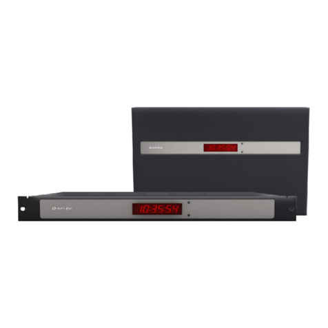
Stand-alone system built in a ½ 19" module. As a standard it requires 230/120 V AC, further
voltage supplies are possible on request.
System 6842G02
System in a ½ 19" wall housing as stand-alone system. A standard 230/120V AC voltage supply
is needed, other voltage supplies are possible on request.
System 6842G03
Stand-alone system built in a ½ 19" table top housing. As a standard it requires 230/120 V AC
voltage supply, further voltage supplies are possible on request.
1DCF77 = (D) German - (C) long wave signal - (F) Frankfurt - (77) 77,5 kHz

INTRODUCTION
Page 6 GPS Satellite Clock 6842 - Ver. 08.00
2Introduction
The hopf_radio- / crystal clock systems well proved since 1975 have been extended by the
GPS2receiver unit 6842, thus enabling the world wide use of this time base at highest precision
level.
The time base is synchronised by the globally installed satellite-navigation system GPS. At a
height of about 20 000 km satellites circle around the earth on different orbits and angles twice
a day. On board each satellite there are high-precision atomic-clocks (precision min. 1x 10E-
12). GPS reception units receive orbit position and GPS world time from as many satellites as
possible. From these values the position of the receiver is calculated. Once the position is iden-
tified the delay time of the received GPS world time is calculated. The precision of the time de-
pends above all on the quality of the position identification.
The world time UTC3is found by subtracting the leap seconds from the GPS-world time (GPS-
UTC); at present (1994) the world time lags 8 seconds behind the GPS-UTC. The difference
varies, depending on the insertion of leap seconds. It is possible for any point in the world to en-
ter, by means of the system key pad, the difference to the UTC-time and the regional time
changeover points for summer/winter time. Therefore a high precision local time is available for
further use.
Various well-tried communication channels like:
• 2 serial RS232 interface
• 2 serial RS422 interface
• 1 kHz frequency output TTL-level
• PPS-pulse TTL-level
• DCF77 simulation of the local or UTC time to control further hopf_radio controlled
clocks
• optional fibre optic interface
are available.
2GPS = Global Position System
3UTC = Universal Time Co-ordinated

SET-UP
GPS Satellite Clock 6842 - Ver. 08.00 Page 7
3Set-up
• connect voltage
• switch on voltage supply
• connect the GPS antenna
• enter local time
• enter time difference
• enter position (not absolutely necessary)
• enter point of changeover S ÖD (not absolutely necessary)
• enter point of changeover D ÖS (not absolutely necessary)
• release program reset
• view time difference
• view position
• view point of changeover S ÖD
• view point of changeover D ÖS
• release master reset
3.1 Voltage Supply
The system is available with different voltage supplies. Therefore please take note of the right
voltage and polarity when connecting the power supply.
The standard voltages available are:
for stand alone systems
• 230 V AC +10%, -15%
• 120 V AC +10%, -15%
Other voltage supplies are available on request
Please Note: SET-UP BY QUALIFIED PERSONNEL ONLY.
3.2 Antenna Installation
The connection to the antenna system is made by the female connector marked "GPS-In".
The correct installation of the antenna system can be found in the Appendix GPS (General
System Information GPS).

SET-UP
Page 8 GPS Satellite Clock 6842 - Ver. 08.00
3.3 Set-up Base System
After supplying the correct operating voltage the device or the board is switched on and runs in-
dependently. The required settings can be entered by means of the key-pad.
3.3.1 Display
In case of the first set-up or a longer time without voltage supply and loss of backup clock in-
formation the following picture is displayed on the 2 x 16 digit LCD display:
LOC.-T:
100:00:00
2 S - C 3- - 4- - / - - - / - - - -
The positions have the following meaning:
1 LOC.-T: 00:00:00
Here the local time is displayed.
2status display: If the standard output is the UTC-display,
UTC: appears instead of LOC.-T:,
position 1 X-- "S" for standard time
"D" for summer time (daylight time)
position 2 -X- "A" announcement of changeover to a different time zone. The
announcement occurs one hour before the time zone changeover.
position 3 --X Display of the internal status of the clock system:
"C" = the clock system runs on crystal operation.
"r" = the clock system is running GPS synchronously but without
seconds and crystal adjustment control
"R" = the clock system runs on GPS reception at highest
accuracy and output of the PPS-pulse (R = radio).
3Display of the days of the week abbreviated:
MO - TU - WE - TH - FR - SA - SU
4Display of the date:
day / short form of month / year
The lighting of the display is switched on as soon as the voltage supply is connected or a key is
pressed. If the key- pad is not used for any entries for 4 minutes the lighting switches itself off
again. Thus ensuring a longer life of the display.
3.3.2 Standard Display
After a power cut ( < 3 days ), the display starts with the internally continued back-up clock in-
formation if it is valid and plausible.

KEY-PAD
GPS Satellite Clock 6842 - Ver. 08.00 Page 9
4Key-Pad
4.1 Key Functions
+/- = entry of sign of numbers
BS = BACKSPACE, deletes the last entry
BR = BREAK, stops all key controls
ENT = ENTER, activates the key pad and takes over entered values
4.1.1 Key-Pad Entry / System Control
The main menu is activated by pressing "ENT".
The display changes from showing the time information to displaying the main menu, where at
present 4 entry or control modes can be selected. The mode wanted is found by entering the
according digit.
Start-picture:
SET = 1 SHOW = 2
S.CLOCK = 3 INI = 4
The modes have the following meaning:
SET: input of set functions like time/date, position, time offset etc.
SHOW: selection of display functions like time difference, position etc.
S.CLOCK: input of set functions like start, stop and pulse of synchronous clock
INI: initialising functions - these functions are required mainly by the production.
They serve to set supervision times and pulse widths.
1234+
5678 -
90AB
BS
CDEFBR
NWS
Y
ENT

KEY-PAD
Page 10 GPS Satellite Clock 6842 - Ver. 08.00
4.2 SET-Functions
When the number 1 is entered the program returns to the set-functions. The program is struc-
tured as a user guidance. All the sub-functions are shown on display and selected by
"Y" = yes or turned down by
"N" = no
any key but "Y" and "BR" is read as no.
When "N" is selected the next sub-function is displayed. At present the following set functions
can be chosen.
4.2.1 Time/Date Entry
selection picture
SET TIME Y / N _
entry picture
TIME: HH:mm:ss
d.DD/MM/YY.Z
This entry function can set the local time. The entry has two lines and must be complete. Lead-
ing naughts must also be entered.
The positions have the following meaning:
Input 1. step HH = hour range from 00 - 23
2. step mm = minute " from 00 - 59
3. step ss = seconds " from 00 - 59
4. step d = day of the week " from 1-7
1 for Monday...7 for Sunday
5. step DD = day range from 01 - 31
6. step MM = month " from 01 - 12
7. step YYYY = year " from 1990 - 2089
All entries are taken over by pressing the "ENT" key.
If the entry is plausible, the time is taken over into the system, otherwise the information "IN-
PUT-ERROR" is shown for 3 seconds. The set-function is left at "INPUT-ERROR", the stan-
dard picture is displayed again. To continue the entry any key but "Y" and "BR" may be
pressed.
BReak leaves the set program. The standard picture reappears.
Please Note: IN COUNTRIES WHICH CHANGE THEIR TIME-ZONE DURING THE COURSE OF THE
YEAR THE CHANGEOVER TIMES MUST BE ENTERED. (SEE 4.2.3)

KEY-PAD
GPS Satellite Clock 6842 - Ver. 08.00 Page 11
4.2.2 Time Difference
selection picture
SET DIF.-TIME Y/N _
entry picture
DIF-TIME: _
By means of this function the time difference between the local standard time and the world
time (UTC time) is entered. The sign indicates in which direction the local standard time devi-
ates from the world time.
Generally:
+ means east
– means west of the 0 meridian.
As most countries in the world chose their time difference in full hours, the entry is made in hour
steps.
e.g. + 05:00; - 11:00
Some countries though have shorter time steps. Here minutes can be entered.
e.g. + 05:30; - 8:45
Please Note: THE TIME DIFFERENCE ALWAYS REFERS TO THE LOCAL STANDARD TIME, EVEN IF
THE SET-UP OR ENTRY OF THE TIME DIFFERENCE OCCURS DURING THE SUMMER
TIME.
4.2.3 Time Zone Changeover
Some countries in the world, depending on the season, have two time zones - a standard time
(also called winter time) and a summer time. The summer time has a time offset of +1 hour
compared to the standard time. The exact change over date for the current year is calculated by
means of the entered parameters. The parameters allow a change over to any point of time.
The user is informed by the show-function where the exact date is stated. If the country has no
time zone changeover, naughts are entered in all positions.
selection picture
for daylight saving/standard time changeover for the standard/daylight saving time changeover
SET CHANGE-OVER SET CHANGE-OVER
DATE DÆS Y/N DATE DÆS Y/N
(Daylight saving time ÖStandard time) (Standard time ÖDaylight saving time)
entry picture
D ÆS hh/d/w/MM S ÆD hh/d/w/MM
> >

KEY-PAD
Page 12 GPS Satellite Clock 6842 - Ver. 08.00
The entries have the following meaning
hh = the hour when the changeover is due
00 ... 23 h
d = the day of the week when the changeover is due
1 = Monday ... 7 = Sunday
w = the number of the day of the month when the changeover is due
1 ... 4 day of the week e.g. 1 ... 4 th Sunday in the month
5 last day of the week e.g. last Sunday in the month
MM = the month when the changeover is due
The entry is completed by ENT.
4.2.4 Position
selection picture
SET Position
Y/N _
By means of this function the geographic position of the unit is entered. This function helps at
first set-up, because it shortens the initialising of the GPS receiver, but it is not essential.
entry picture
LT._
Longitude and latitudes are entered with degrees and minutes starting with the sign for the lati-
tude:
N = northern hemisphere
S = southern hemisphere
then degrees and minutes are entered, (two digits each), and 4 digits after the minutes.
entry picture
LT.N51°12,3651
LT._
The longitude entry starts with:
E = east of the 0 meridian
W = west of the 0 meridian,
then follows the entry for degrees - three digits - and after the separation point the minute entry
follows (- two digits -) plus 4 digits after the minutes.
e.g. N51°12.3651
E007°37.8426
When "ENT" is pressed all entries are taken over.

KEY-PAD
GPS Satellite Clock 6842 - Ver. 08.00 Page 13
For a faster synchronisation the GPS receiver only needs the entry of the approximate position.
For the precise position in the above example the following entry would suffice:
N50°00.0000
E006°00.0000
4.2.5 Status and Pulse Output
There is a programmable output available at the connector strip (pin 8c) which can be assigned
with status or pulse messages.
The programming is done by entering a byte. The programming is requested by the following
picture:
SET STATUS- OR
PULS-OUTPUT Y/N
Entering (Y)es the entry picture appears
BIT 7654 3210
Only a "0" or a "1" can be set for the individual bits in the second line."1" is to be regarded as
switch-on function. As there is only one output available only one "1" may be set in the byte. In
case of several "1" statuses the function for the lowest bit is implemented.
The bits have the following meaning for the switching of the output to GND.
Bit 7 free
Bit 6 free
Bit 5 DCF77 pulse (time base: UTC)
Bit 4 daily pulse (24 o'clock ) on-period 1 s
Bit 3 hour pulse on-period 1 s
Bit 2 minute pulse on-period 1 s
Bit 1 second marker on-period 250 msec
Bit 0 status radio operation
4.2.6 System Byte
The individual bits in the system byte can be used to switch on/off functions. At present no bit is
in use.
4.2.7 Serial-Interface-Parameter
For each of the two interfaces the parameters like baud rate, parity etc. and the modes can be
entered separately. The following selection pictures appear.
4.2.8 Selection Picture Parameter of Serial Interface
SET COM 0 SERIAL or SET COM 1 SERIAL or SET OPTICAL TRNS
PARAMETER Y/N _ PARAMETER Y/N _ PARAMETER Y/N _
see point 6: Parametering of the serial interfaces.

KEY-PAD
Page 14 GPS Satellite Clock 6842 - Ver. 08.00
4.2.9 Setting Modebyte 1 Selection
selection picture
SET COM 0 or SET COM 1 or SET OPTICAL TRNS
MODE_1 Y/N _ MODE_1 Y/N _ MODE_1 Y/N _
4.2.10 Setting Modebyte 2 Selection
selection picture
SET COM 0 or SET COM 1 or SET OPTICAL TRNS
MODE_2 Y/N _ MODE_2 Y/N _ MODE_1 Y/N _
4.2.11 Selecting Display and DCF77-Simulation
For the display and the DCF77-simulation either local or UTC time can be selected.
selection picture
SET TIME-OUTPUTS
DISPLAY/DCF Y/N _
entry picture
LOC.-T = 0 UTC = 1
DISPLAY / DCF:
This can only be changed as a whole, the following combinations are possible:
display DCF77-simulation
LOC.-TIME LOC.-TIME 0 / 0
LOC.-TIME UTC.-TIME 0 / 1
UTC.-TIME LOC.-TIME 1 / 0
UTC.-TIME UTC.-TIME 1 / 1
4.2.12 LAN-IP-Addresses (Optional)
When the system is extended by one or two LAN-boards the LAN-IP address and another con-
trol bit can be entered via the key-pad.
For further information please see description LAN-board 7270
4.2.13 Frequency Input (Optional)
If a frequency output board is added to the system this function can be used to enter the fre-
quency between 1 Hz to 10 MHz in steps of 1 Hz. The input mode is described in the descrip-
tion for the board 7530.

KEY-PAD
GPS Satellite Clock 6842 - Ver. 08.00 Page 15
4.2.14 Key-Word
The entry via key-pad can be protected from unauthorised access by a 4-digit key-word. There
is no key-word entered by our company. The customer must set it himself in the "SET"-menu.
selection picture
SET KEY-WORD
Y/N
After entering (Y)es the display shows the entry picture.
entry picture
KEY-WORD >_
Now a 4-digit number can be entered as key-word except for the sequence
KEY-WORD >0 0 0 0
because this sequence deletes the set key-word.
Please Note: PLEASE KEEP THE KEY-WORD IN A SAFE BUT KNOWN PLACE.
In case the key-word is lost the circuit board must be returned to our company to be re-
programmed.
The key-word is active the next time you turn to the menu.
When a menu item is selected you will be asked for the key-word.
KEY-WORD >_
Every entry of a digit is indicated by a * and an arrow completes the entry after the fourth digit.
KEY-WORD >* * * *<
"ENT" confirms the key-word. If the key-word is correct the according menu item is displayed.
In case of a false entry the following is displayed for 5 seconds
WRONG KEY-WORD
After the 2nd false entry the following is displayed for 5 seconds
WRONG KEY-WORD
! LAST CHANCE !

KEY-PAD
Page 16 GPS Satellite Clock 6842 - Ver. 08.00
After the 3rd false entry the following is displayed for 5 seconds
WRONG KEY-WORD
and when trying to restart the menu
KEY-PAD
SWITCHED OFF
is displayed.
The entry is blocked for 4 hours. Even rebooting the system does not affect the blocking period.
The system is still fully functional. After 4 minutes the display returns automatically or by press-
ing the (BR) key to the display of the time.
4.2.15 Data Security
All the entry data of points 4.2.2 - 4.2.13 are checked for plausibility and then stored in a voltage
fail-safe EEPROM after the next minute change. To check the values a program reset or a
master reset must be executed so that the stored values in the EEPROM are reread into the
main memory.

KEY-PAD
GPS Satellite Clock 6842 - Ver. 08.00 Page 17
4.3 Checking the Entered Values
To check the entered values or those updated by the GPS receiver, the SHOW-function is
called up.
After jumping to the display of the main menu by pressing "ENT" the number 2is entered. The
first SHOW selection picture appears.
The SHOW-function can be interrupted by "BR" = break at any time.
4.3.1 Time Difference
This functions allows to view the actual time difference between the local time and UTC time.
selection picture
SHOW DIF.-TIME
Y/N _
After pressing "Y" the time difference is displayed e.g. as follows:
DIF.-TIME: +02:00 _
If "N" or any other key except "Y" and "BR" is entered the display jumps to the next selection
picture.
4.3.2 Time Zone Changeover S
Ö
D
This function shows the point of changeover from standard time (winter time) to daylight time
(summer time).
selection picture
SHOW CHANGE-OVER
S ÖD Y/N _
After pressing the Yes key the following is displayed.:
TIME: 02.00.00
7.29/03/1998 S>D
The changeover will be (was) on Sunday 29. March 1998 at 02.00 o'clock
4.3.3 Time Zone Changeover D
Ö
S
This function shows the point of changeover from daylight time (summer time) to standard time
(winter time).
selection picture
SHOW CHANGE-OVER
D ÖS Y/N _
After pressing the Yes key the following is displayed:
TIME: 03.00.00
7.25/10/1998 D>S
The changeover will take place on Sunday 25th October 1998 at 03.00 o'clock .

KEY-PAD
Page 18 GPS Satellite Clock 6842 - Ver. 08.00
4.3.4 Position
By means of this function the entered or the GPS updated position is displayed. 4 decimal
points of the position minutes are displayed. GPS updates the position every second.
selection picture
SHOW POSITION
Y/N _
display
e.g. LT. N51°12.6878'
LN. E007°39.8032' (position of hopf_company in Lüdenscheid)
LT = latitude, LN = longitude
4.3.5 Status and Pulse Output
This function serves to show the programming byte for the output at Pin 8c of the VG strip.
request picture
SHOW STATUS- AND
PULS-OUTPUT Y/N
After entering (Y)es the following is displayed:
Bit 7 6 5 4 3 2 1 0
0 0 0 0 0 1 0 0
This means that at output 8c a minute pulse is programmed.

KEY-PAD
GPS Satellite Clock 6842 - Ver. 08.00 Page 19
4.3.6 Satellite Display
To synchronise the device with UTC, 4 satellites within the view range of the antenna are nec-
essary. At best 9-10 satellites are within the view range of the antenna, out of which 6 can be
received parallel.
By means of the menu choice
SHOW SATELLITES
Y/N _
the number of satellites within view, the number of received satellites and the relative measure
for the reception power are displayed.
This function is particularly helpful during the installation of the device. After the menu item has
been selected the following picture appears on display
V : :
: :
Under (V)isible the number of satellites visible for the ideal antenna position on this location is
shown. This is a theoretical value.
Six satellites can be received but only four satellites can be shown in the display. Therefore the
display switches over every five seconds.
The number before the colon is the satellite-pseudo-random-number. The satellites are not
numbered 1, 2, 3 etc. but they have a pseudo random number under which the satellites broad-
cast their information. In case of a satellite failure a spare satellite can be activated under the
same number.
The number after the colon stands for the signal-noise-ratio as relative figure. This can range
between 0-255.
After the first installation it can take up to 1 hour before anything is written in the picture, de-
pending on the start information the system receives (see programming time, position) and on
the antenna position e.g. only half the sky within view.
If there are values in the system the display can look as follows:
V 05:137 17:043
07 : :
7 satellites are in the theoretically visible range. The GPS receiver receives satellite 05 at a sig-
nal/noise ratio of 137 and satellite 17 at a signal/noise ratio of 43.
This number does not suffice for a synchronisation with UTC.
In case of a bad signal/noise ratio the value ranges between 10 - 30
In case of a sufficient signal/noise ratio the values range between 30 - 70
In case of a good signal/noise ratio the values range between > 70
Please Note: TO AVOID ERRORS IN THE MENU SELECTION, LEAVE THIS FUNCTION ONLY BY THE
"BR" KEY.

KEY-PAD
Page 20 GPS Satellite Clock 6842 - Ver. 08.00
4.3.7 Error Interpretation
Errors in the reception system can be recognised by means of the display picture of the satel-
lites.
Example 1
No satellite appears in the display even after several hours after the first installation.
Possible faults:
• the antenna cable has a defect
• the antenna cable is not connected
• the antenna has a defect
• the lightning protection has a defect
Example 2
There are 7 satellites in the view range, but only up to 2 appear on the display.
Fault
• the visible range of the antenna is too small.
Example 3
9 satellites appear within the view range, 6 are received but the system does not synchronise
because the signal/noise ratios all range between 10-25.
Possible faults:
• the cable is too long
• the BNC-connectors are badly assembled
• the cable is crimped or bent
• the cable have the wrong impedance
Example 4
The system has run perfectly so far. 7 satellites appear in the view range, none are tracked, the
system has been running without reception for several days.
Possible faults:
• the cable has been damaged
• a flash of lightning has occurred and the lightning protection has a defect
• the antenna has a defect
• the receiver has a defect
• the voltage supply has a defect
Table of contents
Other hopf Clock manuals
Popular Clock manuals by other brands

Cole Parmer
Cole Parmer Traceable 1065 instructions

Sentry
Sentry ATC-20 Operation instructions

Mini Gadgets
Mini Gadgets HCClockToon user manual

La Crosse Technology
La Crosse Technology WT-5721 instruction manual

Honeywell
Honeywell RCW33W - Atomic Wall Clock user manual

Hyundai
Hyundai AC 321 W instruction manual