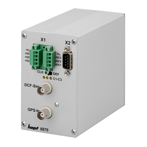
hopf 6038 Parts list manual

version 03.01 09.08.99
Technical Description
GPS-Clock as 8 Bit ISA PC-Board
6038

Company Info hopfhopf Elektronik
version 03.01 page 2
hopfhopf__Elektronik
Nottebohmstr. 41 58511 Lüdenscheid
Post box 1847 58468 Lüdenscheid
tel.: ++49 (0)2351 / 938686
fax: ++49 (0)2351 / 459590
internet: http://www.hopf-time.com
e-mail: [email protected]

Table of Contents hopfhopf Elektronik
version 03.01 page 3
CONTENTS Page
1 Brief Information Model 6038 5
2 Introduction 6
3 Starting the Radio Clock Circuit Board 6038 6
3.1 Antenna Installation 6
3.2 Coaxial Cable Installation 7
3.3 Reception Frequencies 7
4 Setting by Means of SERVICE. EXE 8
4.1 Time, Date, Status Information and Reception Quality 8
4.2 Initialising the GPS Reception Unit 10
4.2.1 Setting Time and Date 10
4.2.2 Setting the Position Data 11
4.2.3 Setting the Difference Local/UTC 11
4.2.4 Points of Changeover 12
4.2.5 Setting DCF77-Simulation and Sync-bit 12
4.2.6 Time Decoding 3D / Position fix 13
4.3 Hardware Setting Base Address 14
4.4 Setting the Output Mode and DCF77-Simulation 14
4.5 Setting the Parameterbyte for the Serial Interface 16
4.6 Setting the Modebyte for the Serial Interface 16
4.7 Show Points of Changeover, Radio Bit, DCF77-Sim and Evaluation Mode 16
4.8 Activate Reset of the Clock Board 16
5 LED on the Front Panel 17
6 Output pulses 17
7 Files on the Disc 17
8 Error during the Reception Process 18
9 Delivery Condition 19
10 Description of the Front Panel of the Board 20
11 Technical Data 21

Table of Contents - continued hopfhopf Elektronik
version 03.01 page 4

GPS PC-board 6038 hopfhopf Elektronik
version 03.01 page 5
1 Brief Information Model 6038
The hopfhopf__system 6038 is a further development of the DCF77 radio controlled clock 6036. The
measurements are the same as the standard format for a short 8-bit ISA bus board. The follow-
ing construction features were particularly focused on:
• potential free antenna circuit
• no line loss caused by insertion of the indirect lightning protection
• antenna cable up to 150 m by simple looping in of an amplifier into the antenna ca-
ble without its own power supply
• downwards compatible with the board 6036 (I/O range)
• simple access to the clock data via the I/O range incl. milliseconds
• no replugging of jumpers required! All address and mode settings are carried out by
the software included in the delivery.
• back-up clock function with maintenance free memory element
• TTL pulse outputs
• interrupt operation with freely programmable cyclic interrupt variable from 10-65536
milliseconds (ideal for measuring purposes)
• GPS reception analysis function
• RS232 interface equipped for the synchronisation of remote computers
• Variable pulse breadth adjustment for DCF77-simulation
• Synchronisation with one or several satellites possible
included software:
• service programme for the setting of all parameters in the clock board
• DOS synchronisation programme
• Windows 3.x, 95 synchronisation programme
Included options:
• programmable protection mechanism for software producers (Dongle)
• software driver for Windows NTTM

GPS PC-board 6038 hopfhopf Elektronik
version 03.01 page 6
2 Introduction
The well-proved hopfhopf__radio controlled / crystal clock systems have been extended by the GPS1
reception unit which guarantees high precision running of the clock anywhere in the world.
The time basis is synchronised by the global satellite navigation system GPS. At a height of
about 20.000 km, satellites circle on different orbits and angles around the earth twice a day
(see picture in the appendix GPS). On board each satellite there is a high precision atomic clock
(precision min. 1x 10E-12). The GPS reception unit receives the orbit position and a GPS-world
time from as many satellites as possible. From these data first the position of the receiver is de-
termined. Once the position has been calculated the travel time of the transmission-information
from the individual satellites can be worked out. The accuracy of the time depends above all on
how accurately the position is calculated.
The world time UTC2is calculated by subtracting the leap second from the GPS-world time
(GPS-UTC). At present (1994) the world time is 8 seconds slower than the GPS-UTC. The dif-
ference changes with the insertion of leap seconds. By means of the system key pad or serial
interface the difference to UTC and the regional time changeover for summer- / winter time can
be entered for any location in the world, which offers the local time for further use at high preci-
sion.
Different well-proved ways of communication like:
• 8-Bit ISA-Bus interface via Dual-Port RAM
• serial RS232 interface
• PPS-pulse
are available. Also a DCF77-simulation of the local or UTC-time is integrated so that all
hopfhopf__DCF77 radio controlled clocks can be controlled from here.
3 Starting the Radio Clock Circuit Board 6038
When installing the radio controlled clock the computer and all the connected devices should be
switched off. Open the computer housing, plug the radio controlled clock into a vacant extension
space (8-bit ISA slot), connect the antenna and the clock is ready for operation.
After installation you have to control that there is no contact to any other board plugged in.
3.1 Antenna Installation
To guarantee a GPS-reception as constant as possible, the antenna must have free "view“ of
the whole horizon. The antenna is dimensioned so that it covers satellites over 10° above the
horizon. It requires the reception of 4 satellites to evaluate the position and time (3D mode). If
the view to a part of the sky is blocked by buildings, the GPS-receiver cannot evaluate the exact
time. It will wait until 4 satellites have moved into the free range of view. This can take up to four
hours in case of an unfavourable satellite constellation. Therefore the antenna should be placed
at the highest possible point on the roof (see drawing in the appendix). The quality of the re-
ceived satellites can be supervised by the programme "SERVICE.EXE" (see below).
1GPS = Global positioning system
2UTC = Universal time coordinated

GPS PC-board 6038 hopfhopf Elektronik
version 03.01 page 7
3.2 Coaxial Cable Installation
The antenna is connected to the base device by means of a coaxial cable included in the deliv-
ery. The cable is connected to the antenna with a coaxial coupling at the plate foot of the an-
tenna. This coupling can be disconnected for cable laying purposes. Loosen the screw at the
antenna foot plate and lift the antenna plate (see drawing in the appendix).
Please note : Do not lay the cable next to other HF-, control- or power cables.
The leakage from these cables could disturb the reception because of the very small reception
power.
The cable is connected to the clock device at the BNC connector of the unit. The standard
length of the antenna cable is max. 25 m (hopfhopf__special cable up to 70 m). If the cable is longer
(up to 150 m) a GPS power amplifier must be looped into the antenna cable.
Please note : Utmost care is required when laying the antenna cable.
Please make sure that :
• the bending diameter must not be less than 10 cm in any place
• the casing of the cable must not be damaged
• the cable must not be crimped
Previously mounted BNC connectors are also a problem. Please do not remove the protection
until the cable has been laid.
3.3 Reception Frequencies
The satellites broadcast two frequencies:
L1 at 1.575,42 MHz
and L2 at 1.227,60 MHz
The frequency L1 has been assigned for civil use.
The received power is about -160 dB. The antenna contains a pre-amplifier which boosts the re-
ceived satellite frequency by +20 dB.

GPS PC-board 6038 hopfhopf Elektronik
version 03.01 page 8
4 Setting by Means of SERVICE. EXE
The programme "SERVICE.EXE" serves to supply the radio controlled clock with initialising data
and to check the clock functions. The programme comes in with the following menu.
SERVICE programm for GPS-radio board 6 0 3 8
meaning of the procedures start by key
------------------------------------------------------------------
Time and Date ............................................ 1
Initialisation of the radio board ........................ 2
Changing the hardware address of the radio board ......... 3
Mode for data output and DCF-simulation .................. 4
Set the parameter-byte of the RS 232 interface ........... 5
Set the telegramm-byte 1 of the RS 232 interface ......... 6
Set the telegramm-byte 2 of the RS 232 interface ......... 7
Show change over date, radio bit, DCF-sim. Eval.-Mode .... 8
Reset the radio board .................................... 9
Exit programm ............................................ Esc
(c) hopf Elektronik GmbH Version: 3.00, 18.12.98
4.1 Time, Date, Status Information and Reception Quality
Under point 1 time, date and the internal clock status can be checked. The position data and the
reception quality can be checked in mode 2 in menu point 4 only. It may therefore be necessary
to switch the clock to mode 2, 3, or 4 during the installation phase. Independent from the mode
the following display appears.
Structure of display in mode 1 - 6036 compatible
base address = Hex : 0280 millisecond : 293
---------------------------- -----------------------------------------
Zone hour minute second day of week daymonth year
--------------------------- ------------------------------------------
Local 15 5 41 1 1 4 96
UTC 13 5 41 1 1 4 96
Lo/ST 14 5 41 1 1 4 96
----------------------------------------------------------------------
Status information of the transmission
B7 B6 B5 B4 B3 B2 B1 B0
1 1 0 0 1 0 0 0
radio time leap sec. ST DST ann. free free
----------------------------------------------------------------------
key word = 21845 reception for 10 minutes
----------------------------------------------------------------------
end by pressing key ...
----------------------------------------------------------------------

GPS PC-board 6038 hopfhopf Elektronik
version 03.01 page 9
Supervising the reception quality
Structure of display mode 2 from main menu 4
base address = Hex : 0280 milliseconds : 293
----------------------------------------------------------------------
zone hour minute second day of week day month year
----------------------------------------------------------------------
ST/WT 15 5 41 1 1 4 96
----------------------------------------------------------------------
data of position: latitude : +51.16587 longitude: -7.3456
difference time UTC/Local: +01 hour 00 minutes
Max Sat.: 7 Revision number : 1.1 date : 01.04.96
Sat.-No.: S/N: 05/137 17/043 15/080 25/065 32/090 00/000
----------------------------------------------------------------------
Status information of the Transmission
B7 B6 B5 B4 B3 B2 B1 B0
1 1 0 0 1 0 0 0
radio time leap second. ST DST ann free free
----------------------------------------------------------------------
key word = 21845 reception for 10 minutes
----------------------------------------------------------------------
end by pressing key ..
----------------------------------------------------------------------
In the setting 3D of the time evaluation 4 satellites within the view of the antenna are required to
synchronise the system with the time. At best 9-10 satellites are within the view of the antenna,
while 6 satellites can be received parallel. Mode 2 menu item 4 allow control of the number of
satellites within the view and which satellites can be received, also a relative measure of the re-
ception power is transmitted.
The time evaluation can also be done in the position fixed mode which requires only one satellite
for synchronisation (see chapter 0).
The entry "Max Sat." states the number of visible satellites. Six satellites can be received. The
entry "Sat.:No/S-N" states the satellite-pseudo-random-number.
The satellites are not numbered 1, 2, 3, etc. but named after the pseudo-random-number of the
satellite broadcasting its information. In case of a satellite failure a spare satellite can be acti-
vated under the same number. The figure after the slash indicates the signal/noise ratio. It can
vary between 0-255.
After the first installation it may take up to 4 hours before satellite data are at hand. It depends
on the start information received by the system (see programming time, position etc.) and on the
antenna position e.g. half the view range to the sky.
In the above screen there are 7 satellites in the theoretical view range, of which e.g. satellite 05
is received by the GPS-receiver with a relative signal/noise ratio of 137 and satellite 17 with 43.
The values of a bad signal/noise ratio lie within 10-30
The values of a sufficient signal/noise ratio lie within 30-70
The values of a good signal/noise ratio lie within 70 and higher
GPS PC-board 6038 hopfhopf Elektronik
version 03.01 page 10
4.2 Initialising the GPS Reception Unit
To speed up the initial synchronisation the service programme can be used to set the time, date
and the position data at the place of use. If required also the points of changeover for summer
and daylight saving time must be entered. The respective selection menu for initialising pops up
when the menu item 2 "initialising clock board" is called up.
Keep the following sequence when setting start values in the system.
1. input of the approximately position data
2. input of the difference time UTC-local
3. input of the actual local time
4. input of changeover points daylight saving and standard time
5. release a reset of the clock after the next minute-change
After the programme has been called up, menu point 2 is used to initialise the GPS-reception
unit.
The following selection menu is shown:
meaning of the procedures start by key
------------------------------------------------------------------
Set time and date ......................................... 1
Set position data ......................................... 2
Set difference time UTC - Local ........................... 3
Set change over daylight saving and standard time ......... 4
Set time out DCF77 simulation and sync.- bit .............. 5
Set Evaluation Mode 3-D / Position fix .................... 6
Back to the main menu ..................................... Esc
after pressing the according key the data can be entered and transferred to the clock.
4.2.1 Setting Time and Date
This menu point is used to set the valid time information. The calculation of daylight saving and
standard time will be done automatically in case of programmed changeover points (look at pt.
Setting Points of Changeover) and is shown after the next complete minute changeover.
key >1< set the time.
The entry dialogue appears where the time, day of the week and date data must be entered
plausibly. When the entry is complete the data are transferred to the clock and taken over into
the internal crystal clock after another check.
On the next minute change the entered data are loaded into the back-up clock. After every reset
or voltage failure the data are read from there. If the voltage failure takes longer than 3 days the
values of the back-up clock become invalid.
Menu point 1 in the main menu serves to check the entry.

GPS PC-board 6038 hopfhopf Elektronik
version 03.01 page 11
4.2.2 Setting the Position Data
This function serves to enter the geographical position of the system. This function is helpful for
the first installation but not necessary; it shortens the re-initialisation of the GPS-receiver. The
following dialogue appears after menu point 2 of the initialising menu has been selected:
set position data:
actual geographical latitude: (+ means north, - means south)
degree (+89 to -89) = +51
degree (0 to 59) = 12
actual geographical longitude: (+ means east, - means west)
degree (+179 to -179) = +007
degree (0 to 59) = 39
All entries are taken over by the entry key.
Latitudes and longitudes are entered in degrees and minutes. The entry must include the sign.:
Latitude: +northern hemisphere Longitude: +east 0°
–southern hemisphere -west 0°
Once the entry is complete the data are checked and transferred to the clock. A reset will be re-
leased in the clock so that the reception process can start with the new data.
After the successful transfer the following message appears:
transfer position data latitude = : 51:12
transfer position data longitude = : 7:34
ready !, end by key ...
For a faster synchronisation the GPS-receiver only needs the entry of a rough position. For the
above example the following entry would suffice.
+ 50°00
+ 007°00
4.2.3 Setting the Difference Local/UTC
The difference between local time and UTC is entered under point 3 in the initialising menu.
The entered value refers to the difference between UTC and local ST-time (ST=standard).
As the local ST-time does not have a summer / daylight saving time changeover the difference
between UTC and local ST-time stays constant.
The difference between UTC and local time (with summer / daylight saving time changeover) is
calculated by the clock board depending on the entered changeover points of time.
The difference time is requested in hours and minutes, the hours being entered with sign.
+ for time zones east of the longitude 0°
– for time zones west of the longitude 0°

GPS PC-board 6038 hopfhopf Elektronik
version 03.01 page 12
Please note : After enter a new value, the UTC-time will be calculated new. In this
case the clock status is set to zero and time and date must be entered
again.
4.2.4 Points of Changeover
Points of changeover for changing the local time from summer to daylight saving time can be set
under pt. 4 of the menu "initialising the clock board".
If no summer / daylight saving time changeover of the local time is wanted, all data positions
must show "0".
Requested are the following: day of the week (values 1-7 according to the days Monday to Sun-
day), the week in the month of the changeover (e.g. 1st week in the month of the changeover,
values between 1-5), the month, hour and minute of the respective changeover.
Any plausible time on the hour within the value range in the programme menu is permissible as
point of changeover but the minute digits must show the value "0".
When the entry is completed the data are transferred to the clock, and after another check
stored in a fail-safe memory.
On the next minute change the clock calculates from these values the exact date of changeover.
These values are calculated automatically for the subsequent years.
The entered values can be checked under menu item 8 of the main menu "view points of
changeover, radio bit, DCF77-sim, evaluation mode".
Please note : Minute entries other than 0 do not result in correct changeovers.
4.2.5 Setting DCF77-Simulation and Sync-bit
This function under pt. 5 of the initialising menu can be used to delay the changeover of the
status information "radio reception" and the output of the DCF77-simulation in case of changes
into crystal operation by the stated time factor (2-254 minutes). If this value is set to 255, the in-
formation "radio" is permanently transferred or the DCF77-simulation is not switched off
(permanent DCF77-simulation).
Please note : Take over of the value 255 takes approx. 3 minutes.
The possibility to delay the switch-off of the DCF77-simulation and radio bit serves to bridge
small reception gaps, where the clock module 6870 does not fall short of the required accuracy
due to its internal control.
Example:
If an accuracy of more than 1 msec is required, the second pulse produced at the output
must not deviate from the absolute time mark by more than ±1 msec. In case of a maxi-
mum crystal drift (0.1 ppm) in free-running situation, this value would be reached after
1000/0,1 = 10.000 seconds. A signalling of the crystal operation would be necessary after
166 minutes.

GPS PC-board 6038 hopfhopf Elektronik
version 03.01 page 13
Width of the DCF77-Simulation pulses
The transmitter DCF77 broadcasts a data string, which transmits the time information with one
bit per second. The lowering of the amplitude for 100 or 200 msec codes the digital information
(0/1).
Due to the narrow band nature of their antennas, some strange makes of radio controlled clocks
distort the duration of the lowering, so that the respective receiver connected on load side must
be set to a different pulse length. The value for the high pulse can be adjusted in the range of
140-230 msec and the low-pulse in the range of 50-130 msec so that those receivers can run
safely with the DCF77-simulation.
4.2.6 Time Decoding 3D / Position fix
The accuracy of the time evaluation depends on how accurately the position of the operational
location is calculated. At least the reception of 4 satellites is necessary in the 3D evaluation
mode. From the calculated position the transit time of the signal to several satellites is found and
the second marker is produced from the average transit times. The 3D evaluation mode allows
the second marker to have an accuracy of ± 1 µsec.
In case of a fixed position quite often a less substantial evaluation of the second marker suffices
e.g. up to some milliseconds. In the position-fix mode the accuracy depends mainly on the pre-
cise entry of the position of the location of the installation. The calculation of the second marker
starts with one satellite and the entered position already. An entry of the position to ± 1 minute
degree achieves an accuracy of the second marker better than ± 20 µsec. An entry even more
precise can achieve the value ± 1 µsec.
The position-fix mode has the advantage that the clock synchronises with only one received sat-
ellite. The antenna may be installed somewhere where less than ¼ of the sky is visible.
Often it is possible to install the antenna indoors at the window (short cable, no lightning protec-
tion). If 4 received satellites are visible in this mode, the evaluation jumps automatically into the
3D mode and calculates the exact position improving the accuracy to ± 5 µsec for one satellite.
The following entry sequence set the modes
selection picture
Set mode of the GPS Evaluation
1 = 3 D Evaluation
2 = Position Fixed
MODE (1-2) =
Entering "1" or "2" switches the evaluation to the according mode. The entry can be checked in
the main menu under pt. 8. The line
Mode of GPS Evaluation:
shows the set mode:
3-D Evaluation
Position Fixed

GPS PC-board 6038 hopfhopf Elektronik
version 03.01 page 14
4.3 Hardware Setting Base Address
The address of the board in the I/O range of the computer is not set by means of jumpers but
can be changed using the software "SERVICE.EXE". For this operation jumper 2 must be dis-
connected.
Connecting jumper J2 returns the board to its basic setting (Address $280). "SERVICE.EXE"
searches the I/O range for the clock board during the start.
When the programme has been called up the hardware address can be changed by means of
menu point 3. The following note appears:
Warning: This function will change the hardware address of your clock
board. Before you start make sure which address range is still
free in your computer.
The clock board can be addressed in steps of Hex 40 addresses in the I/O
range of the computer between Hex 200 to Hex 1FFF.
The factory preset of base address $280 can be restored automatically by
plugging J2 in (see manual of the board 6038)
[Return] for change address or [ESC] for abort!
In case of return the address can be entered as hexadecimal value. The programme checks
automatically whether the entered address is valid and does not transfer any addresses but
plausible ones ranging from $200 to $1FC0 in steps of $40 into the clock.
example : ($200, $240, $280, $2C0, $300 ... $1F00, $1F40, $1F80, $1FC0)
Please note : A reset is necessary after changing the hardware address. The serv-
ice software have to be started again. The programme does not check
the new address range for addresses which may be used by other
adapter boards.
When the base address is selected the data are transferred to the clock board and stored in a
fail-safe memory.
4.4 Setting the Output Mode and DCF77-Simulation
The board 6038 can operate in 4 different modes. The modes differ in their information at dis-
posal in the I/O range of the board (see pt. time, date and status information). For more informa-
tion about the programming of the clock board and the data at disposal please see appendix
"programming manual“.
In mode 1 6036 compatible all available information are downward compatible to the DCF77
clock board 6036 (factory preset).
This setting is meant for customers using their own software to synchronise their computer
based on the DCF77 clock board 6036 and also for the use of the driver programme
"FUNKINST" and "HOPFTIME" with the command line parameter "u" and "m".
In the modes 2-4 the position-, receiver- and the status information are found in the I/O range
(base address +$10 to base address +$3F).

GPS PC-board 6038 hopfhopf Elektronik
version 03.01 page 15
The address range (base address to base address +$0F) contains the time and date informa-
tion as BCD or binary values compatible with the clock board 6036. If you are using the
hopfhopf__clock drivers "FUNKINST" or. "HOPFTIME" you can operate without the command line
parameters "u" and "m", because the according time information appears at base address to
base address +$0F.
• mode 2 time information local time
• mode 3 time information UTC time
• mode 4 time information local time (standard time only)
example : If you intend to synchronise your computer with UTC the parameter "u" can
be omitted if the board is switched over to mode 3.
The address range (base address + $30 to base address + $3F) is compatible with the clock
board 6036 in all modes.
After selecting menu item 4 in the service programme the following menu appears:
Attention: Change output mode!
First read the paragraph "set output mode" in your manual of the clock board
before changing the settings.
key [ 1 ] mode 1 --> compatible with clock board 6036 local time,
UTC, local time (standard time only)
key [ 2 ] mode 2 --> local time with position data and status in
formation
key [ 3 ] mode 3 --> UTC (Universal Time Coordinated),
with position data and status information
key [ 4 ] mode 4 --> Local Time (standard time only)
position- and status information
your choice 1/2/3/4, or Esc for end !
Esc for end !
After the selection of the mode you will be asked to enter the time base for the DCF77-
simulation integrated in the board. This signal can be used for the synchronisation of other
DCF77 receivers (in TTL level, active low). The output is made at the 9 pole SUB D female con-
nector (please see the description of the board panel).
Here comes a translation.
DCF77-Simulation
key [ 1 ] local time as time base for the DCF77-simulation
key [ 2 ] UTC as base for the DCF77-simulation
Esc for end !
When the time base is selected the data are transferred to the clock board where it is stored in a
fail-safe memory there.

GPS PC-board 6038 hopfhopf Elektronik
version 03.01 page 16
4.5 Setting the Parameterbyte for the Serial Interface
see appendix serial interface
4.6 Setting the Modebyte for the Serial Interface
see appendix serial interface
4.7 Show Points of Changeover, Radio Bit, DCF77-Sim and Evaluation Mode
Under point 8 of the main menu the programmed points of change over can be checked.
Attention: New values will be calculated by the clock at the next minute change. In case of set-
ting new values this function should not be used before the next minute change.
Additionally the information about the time out of the radio bit and the DCF77-Simulation are
made.
The following display appears:
change over to daylight saving time: month 03, hour 02
time 02:00:00 day of week 07 date 29.03.96 worked out
change over to standard time: month 10, hour 03
time 03:00:00 day of week 07 date 23.10.96 active
time out radio bit after 2 minutes
time out DCF77-simulation after 2 minutes
DCF77-simulation length of Hi-Bit 200 milliseconds
DCF77-simulation length of Lo-Bit 100 milliseconds
You must wait at least one minute until the new change over points have
been calculated by the radio controlled clock !
press any key...
here you can control the change over date and it’s status. Also you can control the date, the time
and the day of the week.
Please note : During the output of the points of changeover the time data are invisi-
ble for about 5 seconds. Synchronisation processes running in the
background may contain wrong data.
4.8 Activate Reset of the Clock Board
Menu item 9 of the service programme can be used to activate a reset in the clock. All previ-
ously altered settings in the clock remain.
Please note : Errors may occur during the synchronisation process
(FUNKINST.EXE, HOPFTIME.EXE or other clock drivers already ac-
tive) because for about 2 seconds after a reset the I/O range of the
clock board is faded out (all data positions $FF).

GPS PC-board 6038 hopfhopf Elektronik
version 03.01 page 17
5 LED on the Front Panel
The synchronisation status can also be checked by means of the LED on the front panel.
If the LED flashes at second intervals it means:
the clock is in crystal operation
If the LED is lit permanently:
radio operation
6 Output pulses
The following pulses are available at the 9-pole SUB-D connector:
second pulse length 100 milliseconds
minute pulse length 1 second
hour pulse length 1 second
24 h pulse length 1 second
the signals are delivered in TTL-Level active low (Connection diagram See appendix).
7 Files on the Disc
The supplied system disc for the clock board contains the following files:
• DOS_DRV\Funkinst.exe DOS synchronisation process
• WIN31x\Hopftime.exe Windows 3.x synchronisation process
• WIN95\SyncProc.exe Windows 95/98 synchronisation process
• WINNT\HopfServ.exe Windows NT synchronisation process
• SERVICE_D.EXE service programme for diagnostic purposes (german)
• SERVICE_E.EXE service programme for diagnostic purposes (english)
• IRQEXAPL.PAS example programme to make an IRQ

GPS PC-board 6038 hopfhopf Elektronik
version 03.01 page 18
8 Error during the Reception Process
The reception display in mode 2 of the menu 4 "mode for the data output and DCF77-simulation"
can be used to recognise errors in the reception system.
The display screen: time, date, status information in the service programme, can detect errors in
the reception system.
example 1
After the first installation no satellite appears on display even after several hours.
Possible causes:
• the antenna has no sufficient "view" to the horizon
• the antenna cable is broken
• the antenna cable is not connected
• the antenna is broken
• the lightning protection is broken
example 2
7 satellites are within the view range, but only up to 2 appear on display.
Possible errors :
• the view range of the antenna to the sky is too small.
example 3
9 satellites appear in the view range, 6 are recorded but the system does not synchronise be-
cause the signal/noise ratios are all between 10-25.
Possible causes:
• the cable is too long
• the BNC connectors are badly assembled
• the cable is crimped or bent
• the cable has the wrong impedance
example 4
The system has been working faultlessly. Seven satellites appear within the view range but none
are received, the system has not had any reception for several days.
Possible causes:
• the cable is damaged
• lightning has struck and the lightning protection is damaged
• the antenna is damaged
• the receiver is broken
• the voltage supply has a defect

GPS PC-board 6038 hopfhopf Elektronik
version 03.01 page 19
Failure Cause ISA bus
If your service programme has the following message: "no clock board found" although the
board is in the computer, or some data positions in the menu "view time, date" have faulty val-
ues please check the following:
• if the board is placed correctly into the ISA-bus plug-in position
• if there is a possible address conflict with other hardware
• if the contact surfaces of the board are soiled
If the computer bios-setup allows the choice to run the ISA-bus either synchronously or asyn-
chronously the bus must be switched explicitly to asynchronous mode. The IOCHRDY signal is
needed for an error-free data transmission.
9 Delivery Condition
The clock board 6038 is delivered with the following settings:
• mode 1 - 6036 compatible
• local time as basis for the DCF77 pulse output
• base address $280 (+$40 = $2BF)
• jumper 2 connected (no alteration of address possible)

GPS PC-board 6038 hopfhopf Elektronik
version 03.01 page 20
10 Description of the Front Panel of the Board
BNC-antenna connector
LED crystal/ radio operation
SUB-D connector 9-pole
pin allocation pin allocation
1day pulse 6DCF77 pulse out
2hour pulse 7RS232 RxD
3minute pulse 8RS232 TxD
4second pulse 91 kHz
5GND
Please note : The standard interface cable can't be used while employing the serial
interface.
Table of contents
Other hopf Clock manuals