Morrison Bros. co. 918 Manual

1
Morrison Bros. Co. ‑ Dubuque, IA ‑ 800‑553‑4840
918‑‑‑0188 PP
3-10-17
!
!
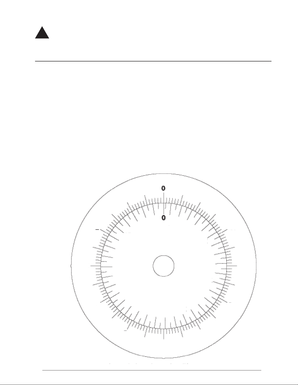
The 918 Clock Gauge is designed to measure liquid level in an aboveground storage tank. The gauge mounts on
top of the tank and is activated by a oat connected to a cable. The 918 is designed to connect to an alarm box
that can provide a high level audible alarm at a desired volume that is set during installation.
Failure to follow any or all of the warnings and instructions in this document could result in a hazardous
liquid spill, which could result in property damage, environmental contamination, re, explosion, serious
injury or death.
NOTE: The most accurate method to calibrate the tank is with uid in it. This will take into account variables
associated with the oat position, the mechanism, and the uid density.
NOTE: Switch contact rating: 125V AC/30V DC, 1 Amp maximums
Gauge Installation & Calibration
WARNINGS
• Fire Hazard – Death or serious injury could result from spilled liquids.
• You must be trained to install or maintain this alarm. Stop now if you have not been trained.
• Any modication to this gauge other than those stated in these installation instructions will void the product
warranty.
• This device is intended to be used as an auxiliary warning to the operator of a possible overll situation and
should not be the only system in place to prevent a tank from overlling. It is the sole responsibility of the
operator to continuously prevent any spillage regardless of the situation or status of the gauge.
• Install in accordance with all applicable local, state, and federal laws.
• For your safety, it is important to follow local, state, federal and/or OSHA rules that apply to working inside,
above, or around the storage tank and piping area. Use all personal protective equipment required for working
in the specic environment.
• Tanks could be under pressure. Vapors could be expelled from tank vents, piping, valves or ttings while
performing installation. Vapors could catch re or cause an explosion. Avoid sparks, open ame, or hot tools
when working on gauge.
• Use a dampened cloth when cleaning the clear front cover of the gauge or 918 alarm box to prevent static
buildup and discharge.
• In the event of malfunction, contact Morrison Bros. Customer Service.
Steps
1. Verify contents of box. You should have received the gauge, oat, installation instructions, re-order/overll
labels, warning tag, cable tie, and optionally the alarm box. Inspect the items for shipping damage. DO NOT
use if damage is found. DO NOT pull and release the cable uncontrollably. This can cause damage to the in-
ternal mechanism and render the gauge inoperable. ALWAYS hold onto cable and allow it to move in a slow
steady motion.
2. Locate the opening, on the top of the tank, where the gauge is to be installed. If possible, select a location
away from the ll port to avoid excessive turbulence that could affect the oat. Also make certain that there
are no objects inside the tank, near the selected opening, upon which the oat and cable could get tangled.
3. Once an opening is selected, measure to the bottom to determine the current liquid level height in the tank.
Record this height in feet and inches (or meters and cm) as you will need it to set the gauge once it is in-
stalled.
4. Apply pipe dope or Teon tape to the male threads on the gauge. If you have a gauge with female threads,
apply the pipe dope or Teon tape to the male threads of the pipe on the tank. DO NOT get pipe dope on the
cable of the gauge.
5. Open the oat clip and attach the oat clip to the swivel end of the cable. Latch the oat clip making sure the
oat clip is securely closed.
918 Clock Gauge
Installation, Operation, and Maintenance Instructions

2
Morrison Bros. Co. ‑ Dubuque, IA ‑ 800‑553‑4840
918‑‑‑0188 PP
3-10-17
!
6. Slowly lower the oat into the tank. Guide the cable through your ngers letting the cable slide through
slowly. DO NOT allow the oat to free fall into the tank as this will cause the cable to come off of the pulley
mechanism and render the gauge inoperable.
7. Once the oat is resting on the liquid level (or tank bottom if the tank is empty) thread the gauge into, or onto,
the tank tting. Use a pipe wrench or strap wrench, on the large hex at the bottom of the gauge, to tighten the
gauge into, or onto, the tank tting.
8. Remove the back plate retaining ring and back metal cover from the gauge. Hold the large pulley wheel in
place and loosen the thumb nut (Figure 1). Insert a small at blade screwdriver into the slot on the end of the
shaft. Rotate the shaft with the screwdriver, which will move the gauge hand, until the gauge hands indicate
the level that you recorded in Step 3. Note: Short hand indicates feet (or meters) and long hand indicates
inches (or cm).
9. Once you have the hands in the correct position, hold the screwdriver rmly in position and tighten the thumb
nut on the shaft.
10. Remove the front face retaining ring and remove the clear front cover.
11. To calibrate the alarm setting, rotate the thumb nut counterclockwise (when facing rear of gauge, see Figure
4) to the desired alarm set point (see Figure 5). This will raise the oat assembly out of the liquid. Be careful
to maintain a rm grasp of the thumb nut to prevent free fall of the oat. While holding the thumb nut steady,
adjust the Alarm hand by pulling the alarm pointer out and rotating it to the point of the triangle (see Figure
6). Once set, carefully allow the oat to drop by turning the thumb nut clockwise (when facing the rear of the
gauge).
Figure 4: Raising the oat Figure 5: Hold thumb nut at Figure 6: Setting Alarm pointer.
with thumb nut to desired desired trip point. Example - Example - Alarm will now sound
alarm trip point. Alarm set point at 9 feet-0 inches. when level reaches 9 feet - 0 inches.
12. If installing the alarm box, leave the gauge front and rear covers removed. If the alarm box will not be
installed, or will be installed at a later date, replace the front and rear covers of the gauge.
Alarm Installation and Testing
Refer to 918S, 918D, 918Q Series Alarm Installation, Operation and Maintenance Instructions.
Failure to follow any or all of the warnings and instructions in this document could result in a
hazardous liquid spill, which could result in property damage, environmental contamination, re,
explosion, serious injury or death.
��������
�����������
�����
Shaft &
Thumb Nut
Large Pulley
Wheel
Fig. 1 STANDARD VERSION
Small hand = Feet
Large hand = Inches
EXAMPLE:
Clock reads 9:27;
Liquid level is 9 feet,
5.25 inches.
Fig. 2 METRIC VERSION
Small hand = Meters
Large hand = Centimeters (x10)
EXAMPLE:
Liquid level is 2 meters,
40 centimeters.
Fig. 3

3
Morrison Bros. Co. ‑ Dubuque, IA ‑ 800‑553‑4840
918‑‑‑0188 PP
3-10-17
!
Operation
Steps
1. To determine the height of uid in the tank, read the position of the gauge hands. Interpolate if necessary.
Note: Short hand indicates feet (or meters) and long hand indicates inches (or cm). See Figures 2 and 3
above.
2. The tank manufacturer’s chart will be required to translate uid height into uid volume.
3. Before a tank ll is initiated, the alarm should be checked for proper operation and sufcient loudness by
pressing the Test/Cancel button. When the button is released, the alarm should cease.
Refer to 918S, 918D, 918Q Series Alarm Installation, Operation and Maintenance Instructions.
4. If the alarm sounds while the tank is being lled, immediately halt lling operations.
Refer to 918S, 918D, 918Q Series Alarm Installation, Operation and Maintenance Instructions.
Maintenance
This gauge should be maintained per applicable codes, or at least once each year.
Refer to 918S, 918D, 918Q Series Alarm Installation, Operation and Maintenance Instructions.
WARNINGS
• Fire Hazard – Death or serious injury could result from spilled liquids.
• You must be trained to install or maintain this alarm. Stop now if you have not been trained.
• Any modication to this gauge other than those stated in these installation instructions will void the product
warranty.
• This device is intended to be used as an auxiliary warning to the operator of a possible overll situation and
should not be the only system in place to prevent a tank from overlling. It is the sole responsibility of the
operator to continuously prevent any spillage regardless of the situation or status of the gauge.
• Install in accordance with all applicable local, state, and federal laws.
• For your safety, it is important to follow local, state, federal and/or OSHA rules that apply to working inside,
above, or around the storage tank and piping area. Use all personal protective equipment required for working
in the specic environment.
• Tanks could be under pressure. Vapors could be expelled from tank vents, piping, valves or ttings while
performing installation. Vapors could catch re or cause an explosion. Avoid sparks, open ame, or hot tools
when working on gauge.
• Use a dampened cloth when cleaning the clear front cover of the gauge or 918 alarm box to prevent static
buildup and discharge.
• In the event of malfunction, contact Morrison Bros. Customer Service.
Steps
1. Visually inspect the gauge and alarm for damage or excessive wear. If either is found replace the gauge or
alarm.
2. If necessary, clean the clear front cover of the gauge or alarm box with a damp cloth.
3. Measure the uid height and correlate it to the tank manufacturer’s volume chart to verify the gauge volume
reading. If readings do not match adjust the gauge setting according to the installation instructions.
4. Test the battery level and overall operation of the 918 Alarm Box. Refer to 918S, 918D, 918Q Series Alarm
Installation, Operation and Maintenance Instructions.
5. Check alarm points to an alarming device to verify alarm settings. The tank uid level must be several
inches lower than the alarm level setting.
6. Inspect the warning tag located near the tank ll and off-loading area. If the tag is damaged or difcult to
read, contact Morrison Bros. at (800) 553-4840 for a free replacement tag.

4
Morrison Bros. Co. ‑ Dubuque, IA ‑ 800‑553‑4840
918‑‑‑0188 PP
3-10-17
!Failure to follow any or all of the warnings and instructions in this document could result in a hazardous
liquid spill, which could result in property damage, environmental contamination, re, explosion, serious
injury or death.
Optional Overll and Reorder Label Installation
NOTE: The template (see Figure 7) is intentionally reversed (mirror image) so the labels may be placed on the
inside surface of the clear front cover. Therefore, the lettering of the labels is on the adhesive side and will read
correctly once placed.
Steps
1. Template units are shown in feet (or cm). It will be necessary to determine the desired overll and reorder
points and convert those into feet (or cm) in order to use this template.
2. Remove the front face retaining ring and remove the clear front cover.
3. Place the clear cover onto the template aligning the outside edge to the outside circle.
4. Remove indicator label backing and place label on the clear cover as shown on template. Align wider end
against inside circle and narrower end pointing toward the level you want to indicate.
5. If both overll and reorder labels are used, make sure each is pointing to the correct foot (or cm) reading that
provides the volumes you desire.
6. Reinstall the clear front cover with the labels on the inside. Make sure indicators are in correct location and
wording is readable before putting gauge in service. Replace the front face retaining ring making certain the
ring snaps all the way down into the groove. You will need to use pliers to squeeze the ring into the groove.
The retaining ring is correctly squeezed into place if the ends of the retaining ring do not overlap.
1
2
3
4
5
6
7
8
9
10
11
50
100
150 200
250
300
CM
FEET
Fig. 7: Overll and Reorder Label Template
Popular Clock manuals by other brands

Spectracom
Spectracom TimeView 400 8177 instruction manual

Oregon Scientific
Oregon Scientific BAR339DPX manual

La Crosse Technology
La Crosse Technology 404-3942 quick start guide

MediaShop
MediaShop Starlyf Birdsong Clock Instructions for use

La Crosse Technology
La Crosse Technology 513-149V2 instruction manual

La Crosse Technology
La Crosse Technology K86302 instruction manual