Horizon Fitness MobileMesh User manual

MOBILEMESH HANDHELD DOCUMENTATION
LAST UPDATE 11/6/21
INTRODUCTION
The MobileMesh Radio by Horizon31 is a rugged mobile radio node utilizing the Doodle Labs™ meshing Smart
Radio module. Based on 2×2 MIMO technology, the MobileMesh Radio can achieve a range of 20 km and
throughput of up to 100 Mbps. The MobileMesh radio is ideally suited as the ground control station radio in
unmanned systems applications. It can be connected to a computing device using USB-A, USB-C or Ethernet and
will provide high-bandwidth IP interconnectivity and advanced ad-hoc meshing.
Unique in its class, the MobileMesh radio includes an optional Real-Time Kinematic (RTK) GPS and can be used as
an RTK base station, providing up to centimeter-level positional accuracy.

COMPLIANCE AND ORIGIN
The MobileMesh radio is designed, manufactured and supported in the United States. The radio technology used
inside the radio is developed by Doodle Labs, who has a presence in the United States and Singapore. There is no
network connectivity or data storage located outside the United States, or
administered by any entity domiciled in an adversary country.
We strive to use components from US-owned companies, and refrain to the
extent possible from using components manufactured by an entity domiciled in
an adversary country to include Democratic People's Republic of Korea, the
Islamic Republic of Iran, the People's Republic of China, the Russian Federation,
or, as determined by the Secretary of Commerce, any other foreign nation, foreign area, or foreign non-
government entity engaging in long-term patterns or serious instances of conduct significantly adverse to the
national or economic security of the United States. The MobileMesh is NDAA compliant.
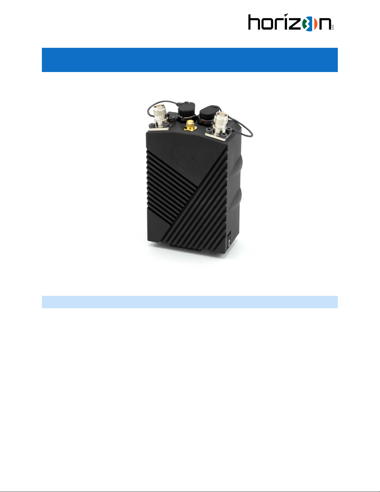
QUICK START GUIDE, MOBILEMESH HANDHELD
To get started, you will need a few components:
•MobileMesh Handheld
•Twist-Lock Battery
•RJ45 “Primary” Cable assembly
•Two RF antennas and (optional) GPS antenna
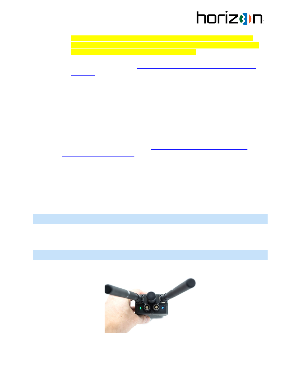
1. Connect the battery:
a. The battery does not have a front or back, you can insert it from either side.
b. Place the battery at approximately a 45-degree angle from the body of the radio with the pogo
pins reasonably aligned with the mating pogo pins.
c. Twist to the right until you hear a click or observe that the latch on the body of the radio has
engaged.
2. Connect Antennas
To remove battery, first push
upward on the release latch,
then twist the battery to the
left.

a. Screw on two TNC-type antennas, ensuring they are the correct frequency for your MobileMesh
radio. We do not recommend powering the MobileMesh without antennas attached.
3. Power on the MobileMesh Radio:
a. Momentarily depress the power switch on the side of the MobileMesh. The Battery and Status
LEDS should come on to let you know power is on.
4. Connect to your host PC:
a. Using H31-MM-CAB-RJ45 (Primary to RJ45) or H31-MM-CAB-USBA-MALE (Primary to USB-A),
connect the MobileMesh radio to your host PC. If you use H31-MM-CAB-USBA-MALE, your
system will enumerate a new Ethernet interface which you will set up in the step below. If you
use the RJ45 cable you will set up an existing Ethernet interface.
i. The Primary connector has 14 pins and is labeled PRI
ii. To insert the connector, align the red dot and press down
iii. To remove the connector, pull upward from the base of the connector. Do not pull on
the cable.
5. Set up your network:
a. Each radio comes from the factory with a 10.223.x.x address. This can be changed later by the
user, but should you ever need to reset the radio, it will default back to this address. The IP
address is provided on a label attached to each radio.
b. To connect, you need your host computer set up in the same subnet.
Momentarily depress to turn the
MobileMesh handheld on. To turn off,
depress and hold for several seconds.

We recommend setting the host computer to a static IP address of 10.223.1.1 and netmask
255.255.0.0. Note: any setting in the 10.223.x.x address space is ok for your host computer, as
long as it is not the same as one of the radios on your network.
For Windows 10, here is a guide: https://www.hellotech.com/guide/for/how-to-set-static-ip-
windows-10
For Ubuntu, here is a guide: https://linuxconfig.org/how-to-configure-static-ip-address-on-
ubuntu-18-10-cosmic-cuttlefish-linux
6. Load the web UI
a. Using a web browser, type the IP address of the radio in the address bar. If successful, the
Doodle Labs web UI will load. From the factory, the username is root and there is no password
set.
For in-depth setup and configuration options related to the internal radio, refer to the Doodle Labs
“Smart Radio -J Embedded” documentation: https://doodlelabs.com/technologies/technical-
library/technical-library-downloads/
7. From the factory, the radios are set to the following:
a. Mode: Mesh Point
b. SSID/Mesh ID: simpleconfig
c. Security Key (WPA2-PSK): DoodleSmartRadio
Therefore factory-default radios will form an ad-hoc mesh network between themselves. There are
many modes of operation for the radios, please consult the documentation linked above.
POWERING ON AND OFF
The power on, momentary depress the power button
To power off, push and hold the power button for several seconds until you see both LEDs turn off.
LED INDICATORS
The MobileMesh radio has two LED indicators, Battery (BATT) and STATUS. The function of each is explained
below:

The BATT LED monitors the battery level, and changes color based on the table below. The logic includes hysteresis
to avoid flickering of the LED.
Voltage Level
BATT LED Color
11.1V or greater
Green
10.15V – 11.1V
Yellow
Less than 10.15V
Red
The STATUS LED provides information about the current operating state of the radio. Under normal operation the
radio will flash blue during boot, then flash yellow while searching for an associated station, then go green once at
least one connection is made.
LED Status
Description
BLUE FLASHING
The radio is booting
YELLOW FLASHING
The radio has no associated connections
GREEN SOLID
The radio has at least one associated connection
CYAN FLASHING
Later functionality
PURPLE FLASHING
The radio is in the process of a factory reset
RED FLASHING
There is an internal error, generally indicating that there is a software or
wiring issue. This can occur if the firmware is upgraded on the Doodle
without also updating the Horizon31 radio scripts because the firmware
update process may wipe the entire storage space on the Doodle. Please
see “Updating The Firmware” section below.
TACTICAL LED MODE
If the user desires the LEDs to be off, the LED system can be put into a tactical mode. In this mode, both LEDS turn
off, but their status can be checked by a momentary press of the power button. Note that pressing and HOLDING
the power button for several seconds will turn off the radio, so ensure that only a short press is used when in
tactical mode.
To enable Tactical mode, Using the web UI, enable Advanced Settings, then System > LED Control
set “LED Tactical Mode” on (checked) to enable this feature.
INTERNAL GPS
Some models of the MobileMesh include an RTK GPS module inside. If included, the user can access this GPS in
three ways:
Via the host computer
Using cables H31-MM-CAB-USBA-MALE or H31-MM-CAB-USBC-MALE, the uBlox NEO-M8P GPS will
enumerate as a USB device when either of these cables are plugged into the host device. At this point, any
GPS or ground station software should be able to use the GPS data.
Via GPSD on the radio
GPSD is a service daemon that monitors one or more GPS attached to a host computer through serial or
USB ports, making all data on the location/course/velocity of the sensors available to be queried on TCP

port 2947 of the host computer. GPSD is already install on the radio and can be used to make GPS position
available to other devices on the network.
To enable GPSD, on the web UI click Advanced > System > GPS Configuration. Enable GPSD, enable on all
interfaces and select interface /dev/ttyACM0. Be sure that the GPSD rule is enabled in the firewall
settings. For more info on gpsd and available clients, https://gpsd.gitlab.io/gpsd/
Via custom scripts on the radio
Internally, the GPS has a UART connection to the Doodle radio (/dev/ttyACM0, default baud 9600). It is
possible to write and execute scripts directly on the Doodle radio to handle the GPS stream (as an
alternative to using gpsd for example). To gain access to the Doodle radio via ssh or scp, be sure and
enable ssh access via the web UI.
As a reference, refer to the LED control project which executes on the Doodle radio.
https://github.com/horiz31/mobilemesh_led_control
USING PERIPHERALS
The MobileMesh radio’s Auxiliary connector is typically used as a passthrough USB device. When primary USB
cables H31-MM-CAB-USBA-MALE or H31-MM-CAB-USBC-MALE are used, pins 1-4 on the auxiliary connector
provide an additional USB passthrough from the host device. This can be beneficial to organize wiring, or remove
the need for an external USB hub in cases where the host device may only have a single USB port (e.g., phones or
tablets).
In the image above, a joystick is plugged into the Auxiliary port, and can then be used to control the drone via the
GCS application running on the phone.
PRIMARY CONNECTOR PINOUTS
The connector is ODU G81YAR-P14UC00-000L
The mating connector is ODU S11YAR-P14XCD0-0000

Figure 1. Primary pinout (Pin side)
Pin Number Function Direction Notes
1 USB_CC IN Only used for USB-C
2 GND PWR
3 NC
4 ETH_RX- IN 100 Mbps Ethernet
5 ETH_RX+ IN 100 Mbps Ethernet
6 ETH_TX+ OUT 100 Mbps Ethernet
7 GPIO OUT

Pin Number Function Direction Notes
8 VBUS PWR
9 USB D- BIDIR
10 USB D+ BIDIR
11 NC
12 NC
13 ETH_TX- OUT 100 Mbps Ethernet
14 TIMEPULSE
Custom cables are available, or blunt-cut cables (H31-MM-CAB-PRI-BLUNT) can be ordered for custom
connectivity options.
AUXILLARY CONNECTOR
The connector is ODU G81YAR-P08UF00-000L
The mating connector is ODU S11YAR-P08XFG0-0000

Figure 2. Auxiliary Pinout (Pin side)
Pin Number Function Direction Notes
1 VBUS OUT Passthrough USB from host device
2 USB D- BIDIR
This USB connection is a downstream port
of a hub, connected to the host computer connected
Via the Primary ODU USD interface.
3USB D+ BIDIR
This USB connection is a downstream port
of a hub, connected to the host computer connected
Via the Primary ODU USD interface.
4GND PWR
5VBUS_2 OUT Doodle Smart Radio USB VBus
6 USB_2 D- BIDIR
This USB connection goes directly to
The Doodle radio.
7USB_2 D+ BIDIR
This USB connection goes directly to
The Doodle radio.

Pin Number Function Direction Notes
8GND PWR
9 GND PWR
UPDATING THE FIRMWARE
The MobileMesh radio uses stock Doodle Labs firmware, and you can update it as needed using firmware provided
by Doodle Labs. However, we do overlay additional scripts and files to support the “status” LED functions and to
share RSSI data with a connected ground control system. If you update the firmware (e.g., by using the Doodle web
interface), you will want to reinstall these scripts as they may be overwritten during a firmware update.
First, ensure you are connected to the radio and can either ping its IP address or can load the web UI. The
instructions below will download the control scripts and config files. A Windows batch file or Linux make program
are used to copy the config files to the radio using the IP address provided.
1. Download the install scripts: https://horizon31.com/wp-content/uploads/mobilemesh_install.zip
2. Unzip the contents.
3. On Windows, open a powershell window and run ./install.bat %IP ADDRESS%,being sure to
type the actual IP address of the radio.
On Linux, run make IP=%IP ADDRESS% install, being sure to type the actual IP address of the
radio.
For example, in Windows PowerShell to update a radio at 10.223.1.1 you would issue
./install.bat 10.223.1.1
In Linux you would issue
make IP=10.223.1.1 install
4. Power cycle the radio and check functionality of the STATUS LED. If using a Horizon31 GCS, check
connectivity to the radio to obtain RSSI information.
Note if a Doodle password is set, the install script will ask for the password. To save repetitive password requests,
the batch (or make on Linux) file disables the Doodle password, copies the files and then re-sets the password
when complete. This is why you may be asked for the password twice; the first time is permission to remove the
password for the file copies, the second is to set it back to the desired value.

FACTORY RESET
Radios released after November 2021 support the ability to do a factory reset via multiple presses of the power
button.
To do a factory reset:
1. Power on the radio, and wait for it to fully boot (1+ minute)
2. Press the power button in short presses 10 times without pausing. Pressing the button about once per
second is good timing.
3. After ~10 presses, the status LED will start to flash purple.
4. The radio will reset itself to factory settings and reboot. This process may take 3-5 minutes.
5. After 3-5 minutes, check that you can access the web UI at the expected IP address. The factory address is
equal to 10.223.x.y where x.y is the last four hexadecimal digits of the wireless MAC address converted to
decimal. For example, a MobileMesh with MAC 0x00:30:1A:4E:7A:B0 has the last four HEX digits 7AB0 and
so x.y is equal to 122.176 since 0x7A=122 and 0xB0=176. This full IP address in this case would be
10.223.122.176.
6. You will need to reload Horizon31-specific scripts which control the LED and GCS connectivity as these are
wiped in a factory reset. Refer to the section above “Updating The Firmware”.
SPECIFICATIONS
RF:
Doodle Labs™ Extreme Smart Radio Inside
RF Output Power: 2 Watts (33 dBm) (2450 model, may vary by band)
Range: up to 20 km (ground to air, directional antennas)
Maximum Throughput: 100 Mbps (40 MHz Ch.)
ISM License Free Bands: 902-928 Mhz, 2400-2482 Mhz, 3500-3700 Mhz, 5725-5875 Mhz
Licensed Bands: 1350-1390 Mhz,1625-1725 Mhz, 1755-1850 Mhz, 2025-2110 Mhz, 2310-2390 Mhz, 2400-2500
Mhz, 4400-5000 Mhz, 4800-4940 Mhz, 5030-5091 Mhz, 5180-5240 Mhz, 5745-5825 Mhz, 5650-5925 Mhz
Management:
LuCI Web Interface, UCI command line interface and SNMP
GPS:
uBlox NEO-M8P-2 RTK GPS (optional)
Power:
Standard PRC-148 Twist Lock Lithium-Ion battery
Operating Time: 20 hours typical. May range from 6-50+ hours depending on transmit duty cycle.
Optional AC and DC power kits available

LED status for battery level
Mechanical:
4.1 x 2.8 x 1.6 in (excluding battery)
14.5 oz (excluding battery/antenna)
STEP file available upon request/NDA
Environmental:
Temperature: -40°C to +85°C
Humidity 0-95% non-condensing
IP67 (pending formal testing)
Security:
AES-256
FIPS-Level 2 Compliant
NSA Suite B
Available Interfaces:
Primary: USB or Ethernet, ODU AMC Connector
Aux: USB Passthrough, USB Host, TimePulse
Antenna Connection: 2x TNC (RF), 1x SMA (GPS)
Table of contents