Horstmann ComPass B User manual

4023841-001
June 2011
Instructions for Use
ComPass B
100104-0426 Translation of the German version
Dipl.-Ing. H. Horstmann GmbH
Humboldtstraße 2
42579 Heiligenhaus
www.horstmanngmbh.com

Instructions for Use
ComPass B 4023841-001
2
Dipl.-Ing. H. Horstmann GmbH
Contents
Intended Use1. 4
Description of supply2. 4
Scope of delivery2.1. 4
Display Unit2.2. 4
Current transformers2.3. 4
WEGA 1.2 C and WEGA 2.2 C2.4. 5
HR-interface cable set2.5. 5
Capacitive insulators2.6. 6
Device functions3. 6
Fault detection and fault indication3.1. 6
Fault detection3.1.1. 6
Fault direction3.1.2. 7
Voltage ring buffer3.1.3. 8
Inrush current suppression3.1.4. 8
Fault indication3.1.5. 8
Reset modes3.1.6. 9
Measuring the values in a medium-voltage system 13.2. 0
Operator control 13.3. 0
Front panel 13.3.1. 0
RS485/MODBUS interface 13.3.2. 1
Digital inputs/outputs 13.3.3. 1
Power Supply 13.4. 1
Test mode 13.5. 2
Installation 14. 2
Safty instructions 14.1. 2
Plug-in housing for panel mount 14.2. 2
Installation of current transformers 14.3. 2
General 14.3.1. 2
Installation of single-phase current transformers 14.3.2. 3
Installation of summation current transformers 14.3.3. 3
Electrical connection 14.4. 4
Terminal strips 14.4.1. 4
Assignment of terminal strips 14.4.2. 4
Device conguration and commissioning 15. 5
Device configuration 15.1. 5
Voltage calibration 15.2. 6
Commissioning 15.3. 8
Technical Data 16. 8
Appendix A: Parametrization ComPass B 19-23
Appendix B: Menu Conguration ComPass B 24-29

Instructions for Use
ComPass B 4023841-001
General Information!
Before installing and operating this instrument carefully read and understand the contents of this
manual.
The content of this operating manual reects the current state of the art at the date of printing. We
reserve the right to make technical changes at any time and without prior notice as necessary in the
framework of ongoing developments. .
Safty Note!
Installation, connection and commissioning of the device must be carried out exclusively by
a skilled/qualied electrician observing the following safety rules according to DIN VDE0105:
Make sure that the instrument is only used for the purpose for which it has been designed
as described in the present operating manual.
Abbreviations
Abbreviations Meaning
IE>Earth fault
I>> Short-circuit
IBOperating current
IEEarth fault current
IKShort-circuit current
MV Medium-voltage
CT Current transformer
V> Overcurrent
V< Undervoltage
VNE Neutral point displacement voltage
P Active power
Q Reactive power
S Apparent power
Declaration of Conformity
This instrument is in conformity with the requirements of the EC Electromagnetical Compatibility
(EMC) Directive and the EC Low Voltage (LVD) Directive in the current state of issue.
If required, the -Declaration of Conformity may be obtained from the following address:
Dipl.-Ing. H. Horstmann GmbH, Humboldtstraße 2, 42579 Heiligenhaus
3
Dipl.-Ing. H. Horstmann GmbH

Instructions for Use
ComPass B 4023841-001
Intended Use1.
The ComPass B is used in medium-voltage distribution networks and combines the functions of a
directional short-circuit and directional earth fault indicator.
It has been developed and designed
to detect short-circuits and earth faults•
to indicate and remotely signal the fault direction (A or B)•
to measure, indicate and remotely signal load current, voltage, power, cos φ and frequency •
of medium-voltage networks
to monitor the load ow direction (A or B)•
The ComPass B is designed for operation in radial, ring and mesh networks.
It can be used in solidly earthed, low-impedance, resonant earthed or isolated neutral systems.
Description of the device2.
Scope of delivery2.1.
A complete set of ComPass B includes:
1 display unit in a plug-in housing for panel mount•
3 single-phase current transformers,•
alternatively: 2 single-phase current transformers and 1 summation current transformer
Integrated voltage detecting system WEGA 1.2 C or WEGA 2.2 C + 1 set of connection•
leads
alternatively: 1 set of HR-interface cable
alternatively: 3 capacitive insulators + 1 set of connection leads.
Display Unit2.2.
Plug-in housing for panel-mount: 96 x 48 x 96 mm (W x H x D), recommended cut-out di-•
mensions according to DIN: 92 +0.8 x 45 +0.6 mm
Voltage supply: 24–230 V AC/DC ±10 %•
Current transformers (CT)2.3.
Single-phase, split core cable-type current transformer for cable/bushing diameters ranging•
from 15 to 55 mm (Order No.: 49-6024-xxx).
Split core cable-type current transformerFigure 1:
Closed single-phase bushing-type current transformer for cable diameter of•
79.5 mm (Order No.: 49-6025-xxx).
Closed bushing-type current transformerFigure 2:
4
Dipl.-Ing. H. Horstmann GmbH

Instructions for Use
ComPass B 4023841-001
Split core summation current transformer for earth fault detection, for cable diameters ran-•
ging from 40 to 105 mm (Order No.: 49-6023-xxx).
Split core summation current transformerFigure 3:
Make sure current transformers are mounted only on fully insulated i. e. touch-safe conductors.
WEGA 1.2 C and WEGA 2.2 C2.4.
The WEGA 1.2 C or the WEGA 2.2 C is designed as a maintenance-free integrated voltage detec-
ting system that serves to detect and indicate the operating condition of medium-voltage installati-
ons according to VDE 0105, Part 1 and Part 100. The instruments comply with the requirements of
the VDE 0682 Part 415 standard (IEC 61243-5) for capacitive voltage detecting systems.
Besides their main function, WEGA 1.2 C and WEGA 2.2 C, respectively, can provide the tapped
capacitive voltage to the ComPass B in order to measure and detect the fault direction and load
ow.
Integrated Voltage Detecting System WEGA 1.2 CFigure 4:
(without relay contacts)
Integrated Voltage Detecting System WEGA 2.2 C (with relay)Figure 5:
HR-interface cable set2.5.
The HR-interface cable set is used to tap the voltage at capacitive measuring points which is re-
quired for the direction decision and the detection of faults and load ow direction. Various types
are available to cope with different requirements (cable length, connectors) of switchgears offered
in the market.
HR-interface cable setFigure 6:
Example for applicationFigure 7:
5
Dipl.-Ing. H. Horstmann GmbH

Instructions for Use
ComPass B 4023841-001
Capacitive insulators2.6.
In air-insulated switchgear units capacitive insulators are used for voltage coupling to the
ComPass B.
Example for insulatorsFigure 8:
Device functions3.
Fault detection and fault indication3.1.
Fault detection3.1.1.
Figure 9 below represents a schematic illustration of a medium-voltage network. The ComPass B
is or can be installed in any switchgear unit.
The instrument measures permanently the phase voltages and currents taking these values as a
basis for real time calculations of the neutral point displacement voltage VNE and earth fault current
IE.
Based on these values the ComPass B is able to detect faults in medium-voltage networks and also
to determine their characteristics.
Schematic illustration of a MV networkFigure 9:
6
Dipl.-Ing. H. Horstmann GmbH

Instructions for Use
ComPass B 4023841-001
The ComPass B works with the following response criteria:
Overcurrent detection for phase currents (I>>) and earth current (I• E>)
Earth current and neutral point displacement voltage (I• E> & VNE>) for resonant earthed/isolated
networks
Overvoltage (V>) and undervoltage (V<)•
The unit allows individual settings of delay times for all of the above mentioned response criteria.
Whenever one or more of the specied response criteria are met, the ComPass B identies the na-
ture of the error and determines the direction of the fault using the sampled values of the affected
voltages and currents.
Fault direction3.1.2.
Short-circuit/earth fault in solidly earthed & low-impedance systems
As for short-circuits and earth fault in solidly earthed and low-impedance systems, the ComPass B
determines the angle between the fault current and the fault voltage of the affected phases to de-
rive the direction of a fault therefrom. If the impedance angle ranges from -45° to +135°, the Com-
Pass B determines a forward fault (↓B direction).
Earth fault in resonant earthed/isolated systems
As for earth faults in resonant earthed/isolated networks, the ComPass B uses the wattmetric me-
thod. Here the direction of a fault is determined by the phase-to-neutral voltage VNE and the earth
fault current IE.
In some cases it is not possible to determine the direction of a fault, especially when the fault is
located close to the switchgear unit the ComPass B is installed into. In such cases the ComPass B
signals an error without directional indication.
Resonant earthed network operation (cos φ)•
In resonant earthed networks, the ComPass B determines the direction of the active power
of the earth fault (VNE x IE x cos φ)
The ComPass B is provided with an integrated dead zone (non-coloured area, see gure
10) for too low levels of earth fault current IE, or for phase angles that are unfavourably loca-
ted between VNE and IE.
Angle diagramFigure 10:
VNE
7
Dipl.-Ing. H. Horstmann GmbH

Instructions for Use
ComPass B 4023841-001
Isolated network operation (sinφ)•
In networks with isolated neutral, the ComPass B determines the direction of the reactive
power of the earth fault current (VNE × IE × sin φ).
Angle diagramFigure 11:
Voltage ring buffer3.1.3.
If there is a small distance between the location of the fault and the place of installation of the
ComPass B unit, the phase voltages of the affected phases may become too small to be usefull for
the decision of fault direction. For this reason, the Compass B is provided with a ring buffer. The
measured values of all phase voltages are permanently written into this buffer. In case of a fault
these voltages are extrapolated in time in order to obtain information on the phase relation.
Inrush current suppression3.1.4.
The ComPass B uses an inrush current suppression to avoid unintended tripping due to inrush. The
ComPass B can be adjusted such as to detect faults only when the phase voltages were previously
present for a preset time.
G
This function is deactivated in delivery status!
Fault indication3.1.5.
Faults are indicated locally by the multicolour LED and the OLED display, and remotely indicated
via the RS485/MODBUS interface/relays.
Multicolour LED•
The multicolour LED ashes red as long as ComPass B is indicating a fault.
OLED display•
In case of a fault, the OLED display presents a fault message informing on the type and di-
rection of the fault. For indication press any direction on the rocker switch.
VNE
8
Dipl.-Ing. H. Horstmann GmbH

Instructions for Use
ComPass B 4023841-001
Short-circuit tripping ↓B Figure 12:
(direction of the line "forward")
Short-circuit faultFigure 13:
Earth fault tripping ↓B Figure 14:
(direction of the line "forward")
Occurrence of an earth faultFigure 15:
Relays•
The ComPass B is provided with 4 relays. Each relay can be congured individually, for
example in order to indicate various fault types and directions, e.g. relay 1 for a phase-to-
phase fault in forward direction, and relay 2 for phase-to-phase fault in reverse direction etc.
If a relay is congured for momentary contact it will engage for 1s for every fault assigned
to it, whereas, if it is congured for permanent contact, it will remain engaged as long as
ComPass B is indicating the fault. If a second fault occurs, it will disengage for 1s and then
re-engage.
RS485/MODBUS interface•
ComPass B stores every fault in its internal memory. The last 20 events are stored including
date, time and data of fault direction (A or B). In addition, also the measured values are
stored at the time the fault is generated and 2 s before the fault occurs. The memory can be
read out either via the RS485/MODBUS interface or manually on the OLED-Display.
Reset modes3.1.6.
ComPass B can be congured to stop fault indication:
after expiration of a pre-dened time (between 1 min and 24 h) •
via external input contact•
locally via the rocker switch•
by remote control via the RS485/MODBUS interface•
on restoration of system voltage•
9
Dipl.-Ing. H. Horstmann GmbH

Instructions for Use
ComPass B 4023841-001
Measuring the values in a medium-voltage system3.2.
The ComPass B permanently senses the voltage, current and frequency values and performs cal-
culated measurements of P, Q, S and cos φ in medium-voltage distribution networks. It also calcu-
lates the mean values (Ø15 min) and the maximum values (24 h/7 days/365 days, slave pointer).
All values can be read locally on the OLED display or transmitted by remote signals via the RS485/
MODBUS interface.
Operator control3.3.
Front panel3.3.1.
ComPass B can be controlled completely from the front panel which consists of the elements
shown in the gure below.
Front panel control of ComPass BFigure 16:
OLED display•
4x21 alphanumerical characters.•
Multilingual plain text menus (German/English/Dutch/Portuguese).•
Multicolour LED•
Green/Yellow/Red.•
Rocker switch (4 directions)•
Activation of OLED display.•
Navigation through plain text menus.•
Display illumination
In normal operation mode, the display on the front panel is switched off. It is illuminated once the
rocker switch is used (press to any direction). If the rocker switch is not used for 60 seconds, the
display illumination is turned off.
Multicolour LED
The multicolour LEDs signal different operating conditions of the ComPass B (see Table 1). In par-
ticular when the OLED display is not illuminated, the LED gives advanced information that can be
investigated in more detail by the user via the OLED display.
OLED Display
Multicolour LED
Rocker switch
10
Dipl.-Ing. H. Horstmann GmbH

Instructions for Use
ComPass B 4023841-001
LED Meaning
green ComPass B is powered from external supply (permanent light)•
No error (permanent light)•
yellow Test mode (single ashing LED) and device error (double ashing LED; •
contact after-sales service)
red Fault in the MV system (LED ashes)•
No indication, external supply not connected.•
No error present.•
Indication of operating conditions by multicolour LEDTable 1:
Rocker switch
The rocker switch is used for navigating the plain text menus on the display.
Up: Scroll up in a menu.1.
Change (increase) a parameter.
Down: Scroll down in a menu.2.
Change (reduce) a parameter.
Left: Leave menu (abort).3.
Jump to main menu.
Right: Call submenu.4.
Save a changed parameter.
1.
4.
3.
2.
Execute a command.
Rocker switchFigure 17:
RS485/MODBUS interface3.3.2.
The RS485/MODBUS interface is used for remote control, remote readout and remote parameteri-
zing of ComPass B.
The ComPass B uses a 2-wire interface according to the RS485 standard with no line termination
in the ComPass B.
The ComPass B is a MODBUS Remote Terminal Unit (RTU) Slave.
Digital inputs/outputs3.3.3.
The ComPass B is provided with 4 digital (relay) outputs and one digital input. Each relay output
can be assigned with individual functionality either via the front panel control or the RS485/MOD-
BUS interface.
Power Supply3.4.
The ComPass B is powered by an external 24-230 V AC/DC ±10 % supply. An incorporated lithium
cell provides the energy in case of lack of external voltage supply, so the readout of all saved data
is ensured in case of a fault.
If external power supply stops, the ComPass B will stop short-circuit and earth fault detection as
well as MV network monitoring and communication via the RS485/MODBUS interface. It is ensured
that the relays are energized, even in case of a fault.
11
Dipl.-Ing. H. Horstmann GmbH

Instructions for Use
ComPass B 4023841-001
Test mode3.5.
The ComPass B features a built-in test mode. This mode can be activated via the
front panel control•
RS485/MODBUS interface•
external input contact•
During test mode, the ComPass B controls both its electronics and its software. The yellow light of
the multicolour LED starts ashing to indicate the test mode.
If an error is detected on the device, the multicolour LED ashes yellow, either in a double or triple
ash mode which depends on the type of error. Further information on the error can be gathered
either from the front panel control or via the RS485/MODBUS interface (see section 3.1.5).
Installation4.
Safety instructions4.1.
Make sure that the ComPass B is only used for the purpose described in the present opera-•
ting manual.
When installing the device, the “ve safety rules” as dened by the DIN VDE 0105 standard •
and the accident prevention rules as per BGV A3 “Electrical Installations and Equipment”
must be complied with.
Make sure that current transformers are mounted and dismounted and cabling work is exe-•
cuted only in a de-energized condition on the disconnected and earthed medium-voltage
switchgear.
If current transformers remain in the switchgear without being connected to the indicator,•
the leads must be applied to suitable insulated terminals ensuring that such leads are short-
circuited.
Plug-in housing for panel mount4.2.
Insert the plug-in housing into a prepared DIN size cut-out of 92+0.8 mm x 45+0.6 mm on the front of
the switchgear panel and lock it by means of 4 integrated spring clips with self-retaining feature.
Provide a minimum installation depth of 95 mm with connected leads.
If you need to dismount the device, remove the front frame and front plate pushing the retainer
spring clips towards the centre of the device (Order No. of Disassembly Clip: 040401-0008).
Installation of current transformers (CTs)4.3.
General4.3.1.
The CTs are split-core types (allow also for subsequent mounting) and are mounted on insu-•
lated conductors.
Ensure shielding of each conductor is repassed through the yoke of the CT to compensate•
any shield currents (see illustration 18). On connecting the wires to the ComPass B mind
the allocation of the cable lead colours (brown/blue) to the terminals (marking br/bl) and the
respective L1, L2, L3 phases.
G
Make sure current transformers are mounted only on fully insulated i. e. touch-safe conduc-
tors.
12
Dipl.-Ing. H. Horstmann GmbH
Instructions for Use
ComPass B 4023841-001
Installation of current transformersFigure 18:
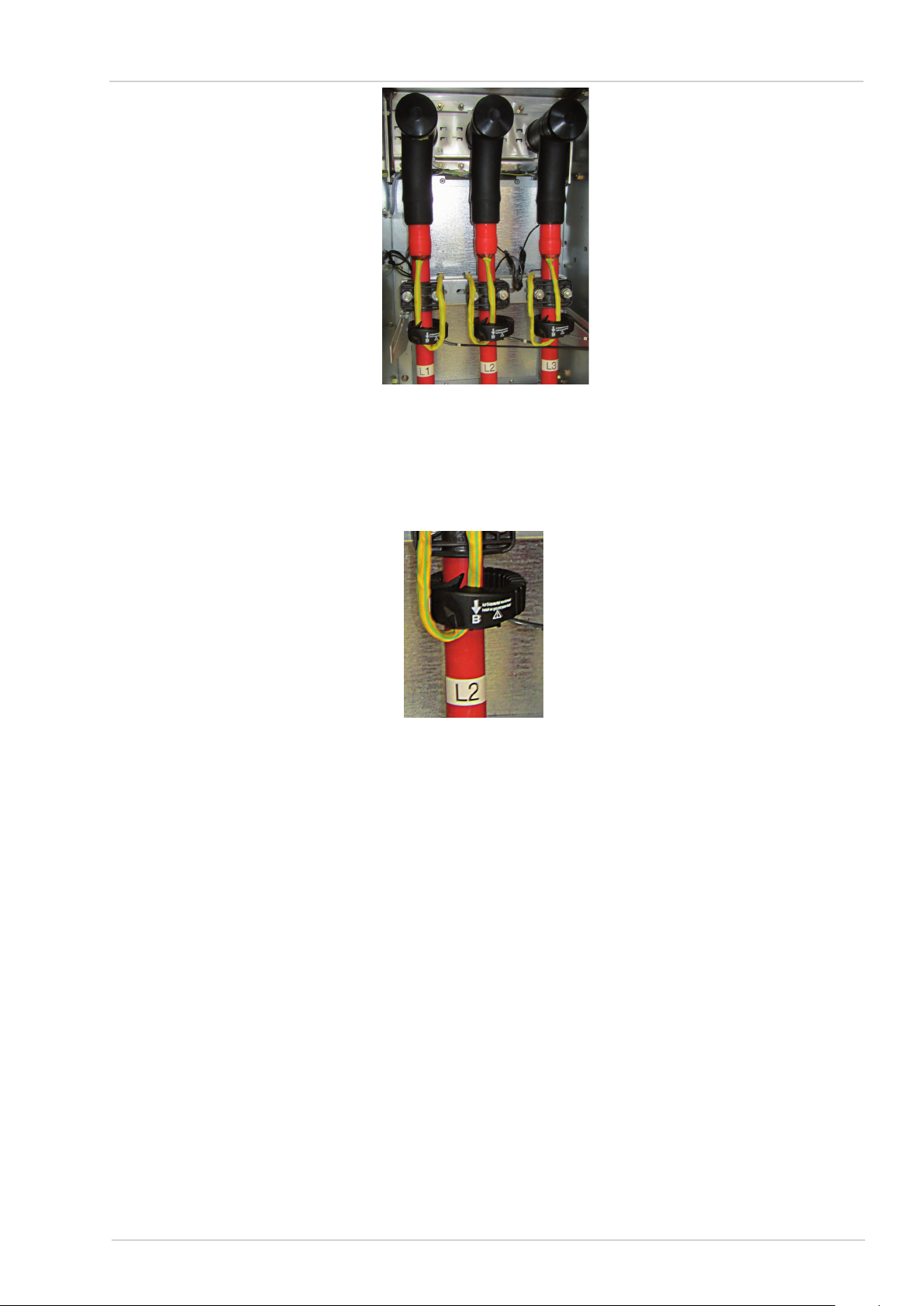
Installation of single-phase current transformers4.3.2.
Install each CT as to ensure that the arrow and the "↓B" show towards the bottom of the switchgear.
Direction indication "↓B"Figure 19:
Installation of summation current transformers4.3.3.
Wrap the CT around all 3 conductors and install it such that the arrow and the "↓B" show towards
the bottom.
13
Dipl.-Ing. H. Horstmann GmbH

Instructions for Use
ComPass B 4023841-001
Electrical connection4.4.
Terminal strips4.4.1.
The terminal strips are located in the rear wall of the instrument. If provided on the side of the
switchgear, perform electrical connection according to the following terminal reference list (See also
circuit diagram on the top side of the instrument, numerical arrangement from right to left). Use fer-
rules of L=6 mm, max. 0.75 mm2 .The maximum permissible tightening torque is 0.4 Nm.
Assignment of terminal strips4.4.2.
Circuit diagram on top side of the instrumentFigure 20:
CT/Digital I/O/Supply Voltage
Terminal No Designation Assignment Direction
1 I1 br CT Phase 1 (brown) Input
2 I1 bl CT Phase 1 (blue) Input
3 I2 br CT Phase 2 (brown) Input
4 I2 bl CT Phase 2 (blue) Input
5 I3 br CT Phase 3 (brown) Input
6 I3 bl CT Phase 3 (blue) Input
7Earth Input/Output
8 Input External input Input
9 Input External input Input
10 K1 Relay 1 Output
11 K2 Relay 2 Output
12 K3 Relay 3 Output
13 K4 Relay 4 Output
14 | Common contact for all relays Output
15 24-230 V ~/+ 24-230 V AC/DC ~/+ Input
16 24-230 V ~/- 24-230 V AC/DC ~/- Input
Terminal assignment of CT/Digital I/O/Supply VoltageTable 2:
14
Dipl.-Ing. H. Horstmann GmbH

Instructions for Use
ComPass B 4023841-001
G
Important note for the connection of the external input (see Table 2)
For activation of the functions use potential-free contacts, e. g. coupling relays or tra-•
cers.
Use separate potential-free contacts for each indication device.•
If the functions of several devices shall be operated in parallel, the triggering disconnec-•
ting elements (relay outputs, coupling relays etc.) are to be operated in parallel.
Operational earth or other "GND" potentials are inappropriate as common reference po-•
tential.
Use a momentary contact for triggering (momentary time 1-5s), but not a permanent•
contact.
MV interface
Terminal No. Designation Assignment Direction
1Earth Input/Output
2 U1 Voltage/Phase 1 Input
3 U2 Voltage/Phase 2 Input
4 U3 Voltage/Phase 3 Input
Terminal assignment of MV interfaceTable 3:
RS485/MODBUS interface
Terminal No. Designation Assignment Direction
1 COM Common Input/Output
2 RES Reserved Reserve
3 RES Reserved Reserve
4 RES Reserved Reserve
5 B D1/RS485 "B" Input
6 A D0/RS485 "A" Input
Terminal assignment of RS485/MODBUS interfaceTable 4:
Device conguration and commissioning5.
Device configuration5.1.
ComPass B is delivered with a standard factory setting (see Appendix A) which, in most cases,
meets all requirements. Some parameters (see Table 5) however need to be set and checked indi-
vidually which can be carried out either via the front panel control or the RS485/MODBUS interface.
G
Any alteration in the conguration should be carried out while assuring that the ComPass B is
supplied by an external supply, otherwise parameter storage may fail.
15
Dipl.-Ing. H. Horstmann GmbH

Instructions for Use
ComPass B 4023841-001
Short-circuit trip current → Settings I>>
Short-circuit current delay time → Settings tI>>
Earth fault trip current → Settings IE>
Earth fault delay time → Settings tIE>
Time reset → Settings tReset
Language → Settings Language
Short-circuit current transformer → Settings CT
Earth fault current transformer → Settings SUM-CT
Frequency → Settings Frequency
Rated voltage → Settings VNom
Neutral earthing → Settings NeutralPt
Relay type → Settings Type
Relay mode → Settings Mode
Parameter setting in the ComPass BTable 5:
Voltage calibration5.2.
Step 1:
G
Voltage calibration is required after ComPass B has been installed in the switch-gear and the
switch-gear has been energised.
Below voltage calibration is carried out using the example of a 11 kV network.
Step 2:
Voltage calibration is possible only, if medium voltage is applied to the switch-gear. The bushings of
the switchgear or the capacitive insulators on the primary side must be connected to a three-phase
medium voltage.
G
If there is no precise reference voltage available, ComPass B must be calibrated using the
network voltage with the impending power supply. In this case, continue with step 4.
Setting the medium-voltage parameterStep 3:
Example: 11 kV system
Un= 11 kV resp.
ULE = Un/√3 = 6,35 kV
Software for the determination of data settings (example).Figure 21:
16
Dipl.-Ing. H. Horstmann GmbH

Instructions for Use
ComPass B 4023841-001
ComPass B menu settings for voltage calibrationStep 4:
Select menu:
Settings →↓ Expert Mode →↓ Grid parameter
- Set frequency to 50 Hz
- Set VNom to 11.0 kV (Voltage used in this example !)
Select menu:
Settings →↓ Expert Mode →↓ V-Calibration
Set VCAL_LL to 11000V.
Note: VCAL_LE entry is changed automatically.
G
Alternatively, set VCAL_LE parameter whereupon
VCAL_LL is changed automatically.
Select entry „Start calibration“ and push rocker switch to the
right.
If the following security prompt appears, V-AutoCal?
=> Select “Yes”.
Note: Presence of calibration voltage of 11 kV/6.35 kV is requi-
red!
Indication on the display during the calibration process.
Indication on the display after calibration has been completed.
Correction values are stored.
Push rocker switch to the left!
Step 5:
Indication:
- Voltage is calibrated.
- Date of calibration.
- Calibration valid for medium-voltage range.
Verification if calibration has been successfully completed:
Applied calibration voltage shall be identical with the voltage va-
lue indicated on the display (to be found in the menu under mea-
surement results).
17
Dipl.-Ing. H. Horstmann GmbH

Instructions for Use
ComPass B 4023841-001
Commissioning5.3.
The ComPass B is ready for operation after the following works have been completed: “Installation”
according to section 4, “Device conguration” according to section 5.1 and “Voltage calibration” ac-
cording to section 5.2.
Technical Data6.
Mechanical data
Plug-in housing for panel mount 96 x 48 x 96 mm (W x H x D)
DIN-cutout dimensions in the switchgear 92+0.8 x 45+0.6 mm
Weight of display unit 240 g
Degree of protection IP40
Electrical data
Power supply Internal supply: 3.6 V lithium cell, with 20-year shelf life
>1000 h total ashing time of the LED
>1000 activations of the display
External supply: 24-230 V AC/DC ±10 %
Power consumption <1 W (DC supply)
<1.5 VA (AC supply)
MV network parameters
Rated voltage 1–36 kV
Frequency 50 Hz/60 Hz
Load current (single-phase) 0–630 A
Short-circuit trip current 50–2000 A
Short-circuit response delay 40 ms < t < 60 sec
Earth fault trip current 20–1000 A (low-impedance/solidly earthed system)
5–200 A (isolated/resonant earthed system)
Earth fault response delay 40 ms < t < 60 sec
Reset options by automatic reset (1 min to 24 h), or
via external contact, or
by means of the rocker switch on the front side, or
on restoration of voltage/current, or
via RS485/MODBUS interface
Current measurement accuracy:
0 A – 630 A 3 % (Resolution 1A)
630 A – 1500 A 5 %
1500 A – 2000 A 10 %
Voltage measurement accuracy: ≤ 10 % (automatic calibration)
≤ 1 % (when using reference voltage for voltage
calibration)
18
Dipl.-Ing. H. Horstmann GmbH

Instructions for Use
ComPass B 4023841-001
External input for connection of a potential-free contact,
congurable function
Digital outputs 4 relays
NC/NO
Permanent contact/momentary contact (1 s)
Contact capacity: 230 V AC/1 A/62.5 VA max.
220 V DC/1 A/60 W max.
Breakdown voltage: 1.5 kV, 1 minute
Current transformers (CT) 3 pcs. single-phase CT (L1, L2, L3)
alternatively: 2 pcs. single-phase CT +
1 pc. summation CT
Environmental Conditions
Operating temperature -30° C... +70° C
19
Dipl.-Ing. H. Horstmann GmbH

Instructions for Use
ComPass B 4023841-001
Settings Assignment Asjustment Default Customer
setting
Basic setting
I>> Short-circuit trip current 50-2000 A 400 A
tI>> Short-circuit response delay 40 ms-60 s 80 ms
IE> Earth fault trip current 1-1000 A (<10 A nur
mit SUM-CT)
200 A
tIE> Earth fault response delay 40 ms-60 s 160 ms
tReset Time reset of the fault indica-
tion and relays
1 min – 1440 min
(24 h)
240 min (4 h)
Expert mode
Language Deutsch
English
Nederlands
Portugues
English
Sensor
Current transformer
(CT)
CT = short-circuit current
transformer
----------------
49-6023-00X
49-6024-00X
49-6025-00X
49-6024-00x
SUM-CT = earth fault current
transformer
------------
49-6023-00X
----------------
Grid parameter
Frequency 50/60 Hz 50 Hz
VNom Nominal voltage 1-36 kV 10.0 kV
Neutral earthing low-impedance earthed
temporary low impedance
earthes
isolated earthed
Resonant earthed
Low-ohmic
KNOSPE
Isolated
Resonant earthed
Low-ohmic
Relais (Each relay has the following conguration options. The standard congurations are available Relay 1 to Relay 4
at the end of this section.)
Type Relay basic setting NO = Normaly Open
NC = Normaly
Closed
Normaly Open
(NO)
Mode Relay basic setting Momentary
Permanent
Momentary
Function
I>> Relay responds to short-
circuit (non-directional)
On
Off
Adjustable for
each relay
I>> A Relay responds to short-
circuit direction A
On
Off
Adjustable for
each relay
I>> B Relay responds to short-
circuit direction B
On
Off
Adjustable for
each relay
Appendix A: Parameterization ComPass B
For unambiguous assignment of the device transfer your serial number (see sticker top panel):
S.No. ........................
20
Dipl.-Ing. H. Horstmann GmbH
Table of contents
Popular Measuring Instrument manuals by other brands


Galvanic Applied Sciences
Galvanic Applied Sciences 943-TGX Operation manual

Hanna
Hanna HI 991300 instruction manual

Endress+Hauser
Endress+Hauser Proline Prosonic Flow 92F Safety instructions

Circutor
Circutor CVM-E3-MINI instruction manual

Airflow
Airflow Silent+ Mini Orange instruction manual

RX only
RX only stryker user guide


