SOURCE (red LED)
SENSOR
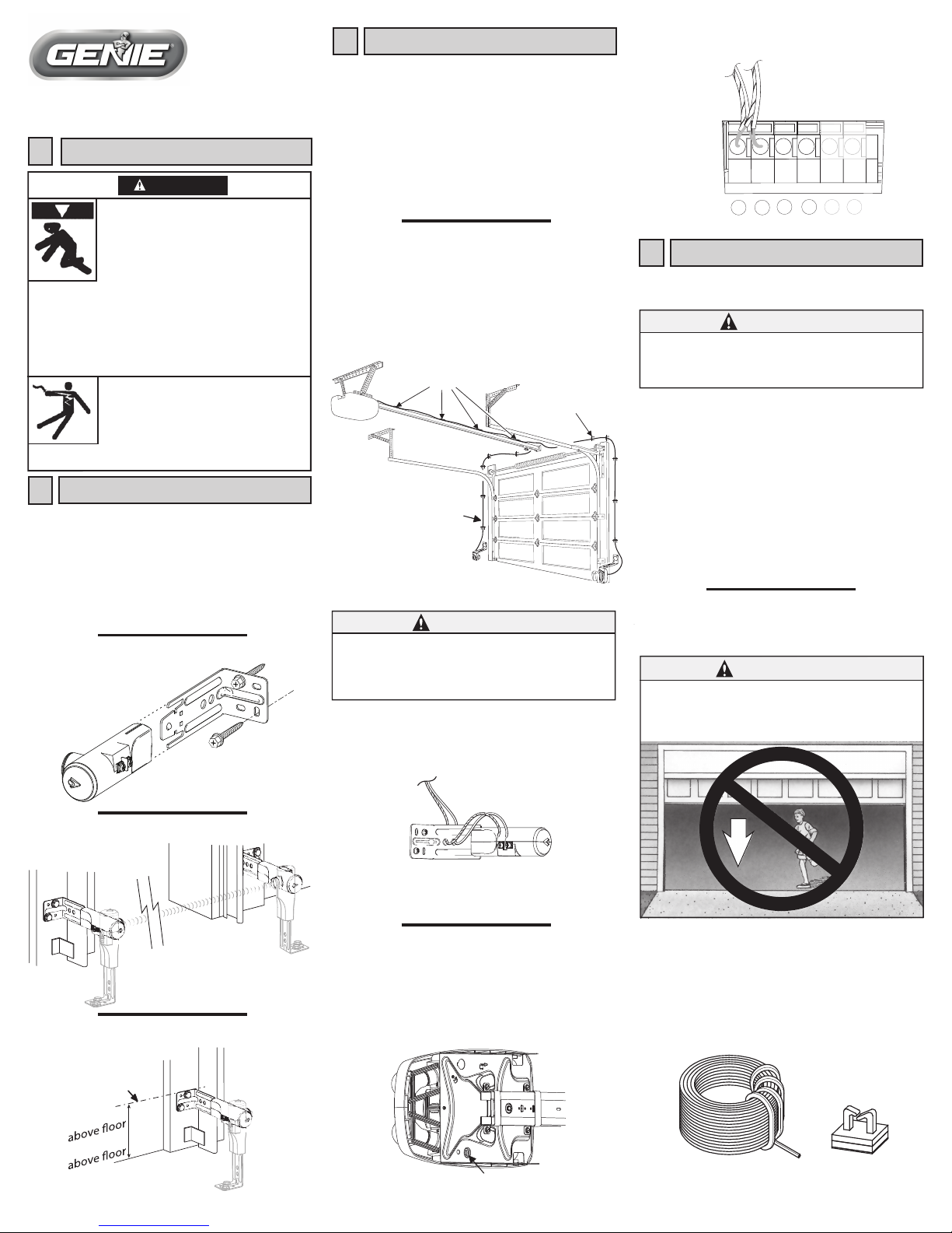
Top of
bracket
6" max.
5" min.
SAFE-T-BEAM®SYSTEM
INSTALLATION INSTRUCTION
IMPORTANT INFORMATION
1
Locations of existing units can be reused if that is desired. Safe-T-Beam®
System (STB) Source and Sensor do not have to be mounted on garage
door frame. They can be placed anywhere along garage door wall that is
convenient for mounting, provided the location meets the
following requirements:
1) They must be placed across the door opening,
2) at proper height,
3) with a clear line of sight between them. (Max. Range is 30 feet).
(They may be mounted on floor, only as a last resort, if there is
no other option. Not recommended.)
Moving Door can cause serious injury or death.
WARNING
MOUNTING SOURCE & SENSOR
2
37252500131
• Wall control must be mounted in sight of
garage door, at least 5 feet above floor and
clear of moving parts.
• Keep people clear of opening while door
is moving.
• Do Not allow children to play with remote or
door opener.
Electrical Shock can cause serious injury or death.
• Power cord must be unplugged before
attaching any wires.
• Be sure wire ends do not touch each other or
other terminals.
If you have questions or if you need a manual,
contact the distributor or manufacturer of the opener.
If Safety Reverse does not work properly:
• Close door, then disconnect opener using manual
release handle.
• Do Not use remote or door opener.
• Refer to Door and Door Opener Owner’s Manuals before
attempting any repairs.
Once location is established, measure height of bracket as
shown. Hold bracket in place and mark hole locations. 1/8" pilot
holes are recommended.
No height adjustment is needed for units mounted on floor.
To ease mounting, source and sensor units can be detached
from the bracket by pulling them apart. After mounting brackets,
slide units back onto brackets.
Ensure there will be an unobstructed path between source
and sensor. Sensor should be mounted on the side of the garage
door opening that receives
the least direct sunlight.
1/4" x 1-1/4"
Lag Screws (provided)
WIRE RUN
3
©2010 GMI Holdings, Inc. D/B/A The Genie Company
22790 Lake Park Blvd., Alliance, Ohio 44601 5/2010
During testing of the Safe-T-Beam® System, be sure to
stay clear of the door and any moving parts. It is
preferrable to use a long-handled object to interrupt the
beam during tests.
CAUTION:
WIRE
WIRE CLIPS
Safe-T-Beam® System must be installed and working properly in order for
door opener to function.
SAFE-T-BEAM® SYSTEM TEST
4
Start door moving in close direction.
Pass an object through the path of the Safe-T-Beam® System in
order to interrupt beam.
— Door should stop and reverse direction to fully open position.
1.
Attach to terminals #1 and #2 (again either wire).
Bundle excess wire and tape to top of power head.
4.
2.
P/N 37125AP/N 37270R
AT OPENER
LOCATED INSIDE THE LIGHT LENS
STB
12345 6
BWC IWC
NOT
USED
NOT
USED
As the door is closing, constantly observe the door
opening to prevent anyone moving into the path of
the door.
If this happens, immediately release button.
WARNING:
If door will not run in closed direction, check for:
• Misalignment of Safe-T-Beam® System
(Red LED on source unit will be blinking).
• Obstruction in path of beam.
• Pinched or broken wire.
• Loose wiring connection.
If you still have a problem , contact Customer Service at 1-800-35-GENIE.
NOTE: If the situation demands that the door be closed, this can be done
by pressing and holding the wall button or wall console button until the
door is fully closed.
Foranswers to any questions, problems or concerns, please
contact Customer Service at 1-800-35-GENIE.
ORDERING INFO:
To order wire or wire clips use following part numbers:
Reuse of existing wiring is easiest and recommended unless it is broken,
cut, frayed or there is a problem. If you can reuse existing wiring —
SKIP FORWARD TO STEP 4. If new wiring must be installed, the path
shown below is recommended.
Need to install new wire? Wire and Wire Clips (for fastening the wire to
the rail) can be purchased through Customer Service at 1-800-35-GENIE
or at a local Genie Professional Dealer using the information at the end of
this instruction. The path shown below is recommended for routing the
wire run.
NO POLARITY
EITHER WIRE TO EITHER TERMINAL IS OKAY
WIRE
CLIPS
INSULATED STAPLES
WIRE
CONTROL WIRE TUBE
Route two (2) lengths of two (2) conductor wire (See above) from
opener, along top of rail.
Fasten wire to rail.
— Evenly space fasteners along rail.
Fasten to header and wall (preferably with insulated staples).
Allow for some slack at the source and sensor units and cut off
any excess wire.
At source and sensor, route wires through bracket as shown and
attach wires at terminals. Either wire to either terminal
(non-polar).
If installing new wiring:
At opener, twist striped wires together. Twist plain
wires together. Feed down through control wire tube “chimney”
at top of opener.
1.
2.
3.
When using insulated staples, be aware that staples which
are too tight can cut or pinch wires. Cut or pinched wires
can cause the Safe-T-Beam® System to stop working. When
using insulated staples, make sure you fasten them only as
tightly as needed to hold the wire snugly.
CAUTION:
1.
3.
2.


