Insert the handle into the frame tubes, unl the snap
buon pops up.
Slide the top tray into the plasc supports on the
handle, as shown in the picture.
Tighten the storage drum screws from step 1.
Insert wheel (Reference 1) onto the cart axle
(Reference 5) and the push the wheel axle (Reference
2) into cart axle.
Put the cover (Reference 3) on the axle and insert the
R pin (Reference 4) into the cover.
Note that the U-pin needs to be inserted into the
socket on the cover.
Repeat the process with the second wheel.
Carefully remove all the packaging and parts from the box.
Li the hose storage drum unl the plate matches the
plate on the frame, ensuring the holes are aligned.
Secure the hose storage drum in place with the “B” -
Threaded screw provided.
Place the hose guide system into the opening of the
handle, and snap in place making sure the black worm
drive is on the boom.
Secure in place using the “A” self-tapping screws
provided.
Metal Hose Reel Cart (3357, 3358)
Metal Hose Reel Cart
User Manual
MODEL: 3557-CH - 3558-CH
Carefully remove all packaging and parts from the box.
ASSEMBLE THE CART
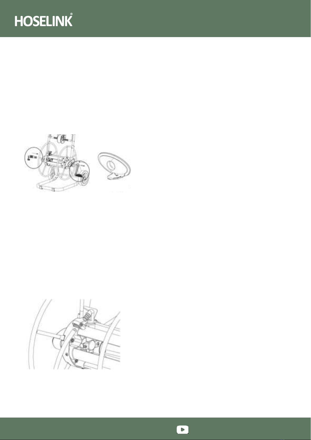
STEP ONE:
•Lift the hose storage drum until the plates are aligned
with the plates on the frame (see figure 1).
•Secure the hose storage drum in place with the B
threaded screws provided.
CAUTION
Please do not tighten these two screws until step 3.
ASSEMBLE HOSE GUIDE SYSTEM
STEP TWO:
•Place the hose guide system into the opening of the
grab handle and snap in place making sure the black
worm drive is on the bottom.
•Secure in place, using the Aself-tapping screws provided.
ASSEMBLE HANDLE AND TOP TRAY
STEP THREE:
Insert the grab handle into the frame’s tubes, until the snap
button pops up (figure 2).
•Slide the top tray into the plastic supports on the grab handle,
as shown in figure 3 below.
•Tighten the storage drum screws from step 1.
CAUTION
Be careful of pinch points when pressing the button into
the holes.
INSTALL WHEELS
STEP FOUR:
•Insert wheel (reference 1) onto the cart axle (reference 5).
Note the wheel axle (reference 2) will already be fitted
to the wheel.
•Put the cover (reference 3) on the axle and insert the
U-pin (reference 4) into the socket on the cover.
•Repeat the process with the second wheel.
1Wheel
2Wheel Axle
3Cover
4U-pin
5Cart Axle
Insert the handle into the frame tubes, unl the snap
buon pops up.
Slide the top tray into the plasc supports on the
handle, as shown in the picture.
Tighten the storage drum screws from step 1.
Insert wheel (Reference 1) onto the cart axle
(Reference 5) and the push the wheel axle (Reference
2) into cart axle.
Put the cover (Reference 3) on the axle and insert the
R pin (Reference 4) into the cover.
Note that the U-pin needs to be inserted into the
socket on the cover.
Repeat the process with the second wheel.
Carefully remove all the packaging and parts from the box.
Li the hose storage drum unl the plate matches the
plate on the frame, ensuring the holes are aligned.
Secure the hose storage drum in place with the “B” -
Threaded screw provided.
Place the hose guide system into the opening of the
handle, and snap in place making sure the black worm
drive is on the boom.
Secure in place using the “A” self-tapping screws
provided.
Metal Hose Reel Cart (3357, 3358)
➜
➜
Insert the handle into the frame tubes, unl the snap
buon pops up.
Slide the top tray into the plasc supports on the
handle, as shown in the picture.
Tighten the storage drum screws from step 1.
Insert wheel (Reference 1) onto the cart axle
(Reference 5) and the push the wheel axle (Reference
2) into cart axle.
Put the cover (Reference 3) on the axle and insert the
R pin (Reference 4) into the cover.
Note that the U-pin needs to be inserted into the
socket on the cover.
Repeat the process with the second wheel.
Carefully remove all the packaging and parts from the box.
Li the hose storage drum unl the plate matches the
plate on the frame, ensuring the holes are aligned.
Secure the hose storage drum in place with the “B” -
Threaded screw provided.
Place the hose guide system into the opening of the
handle, and snap in place making sure the black worm
drive is on the boom.
Secure in place using the “A” self-tapping screws
provided.
Metal Hose Reel Cart (3357, 3358)
Figure 2
Figure 3Figure 1