Contents
Welcome
Notice
Definitions
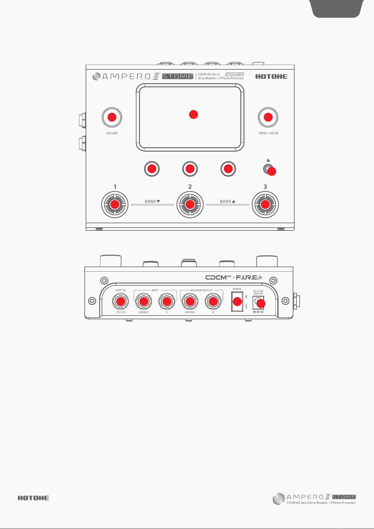
Panel
Getting Started
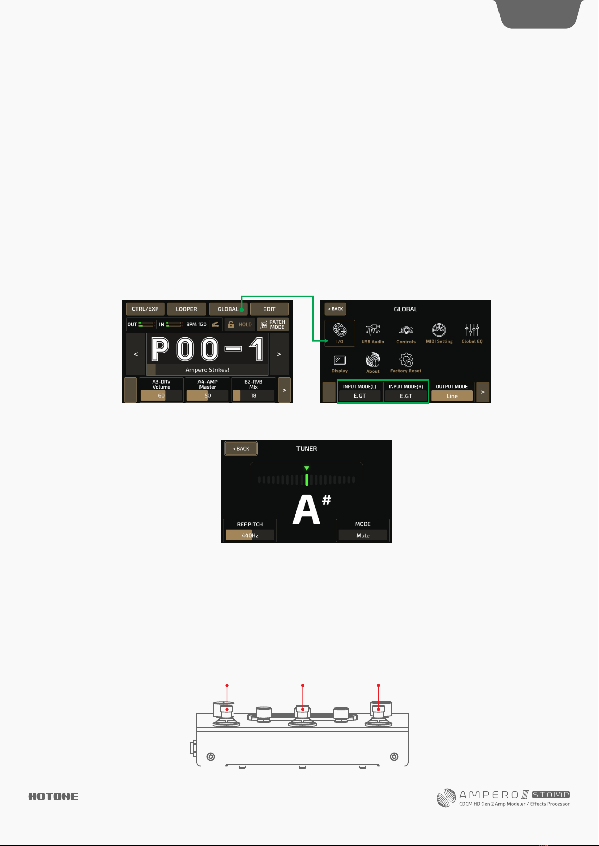
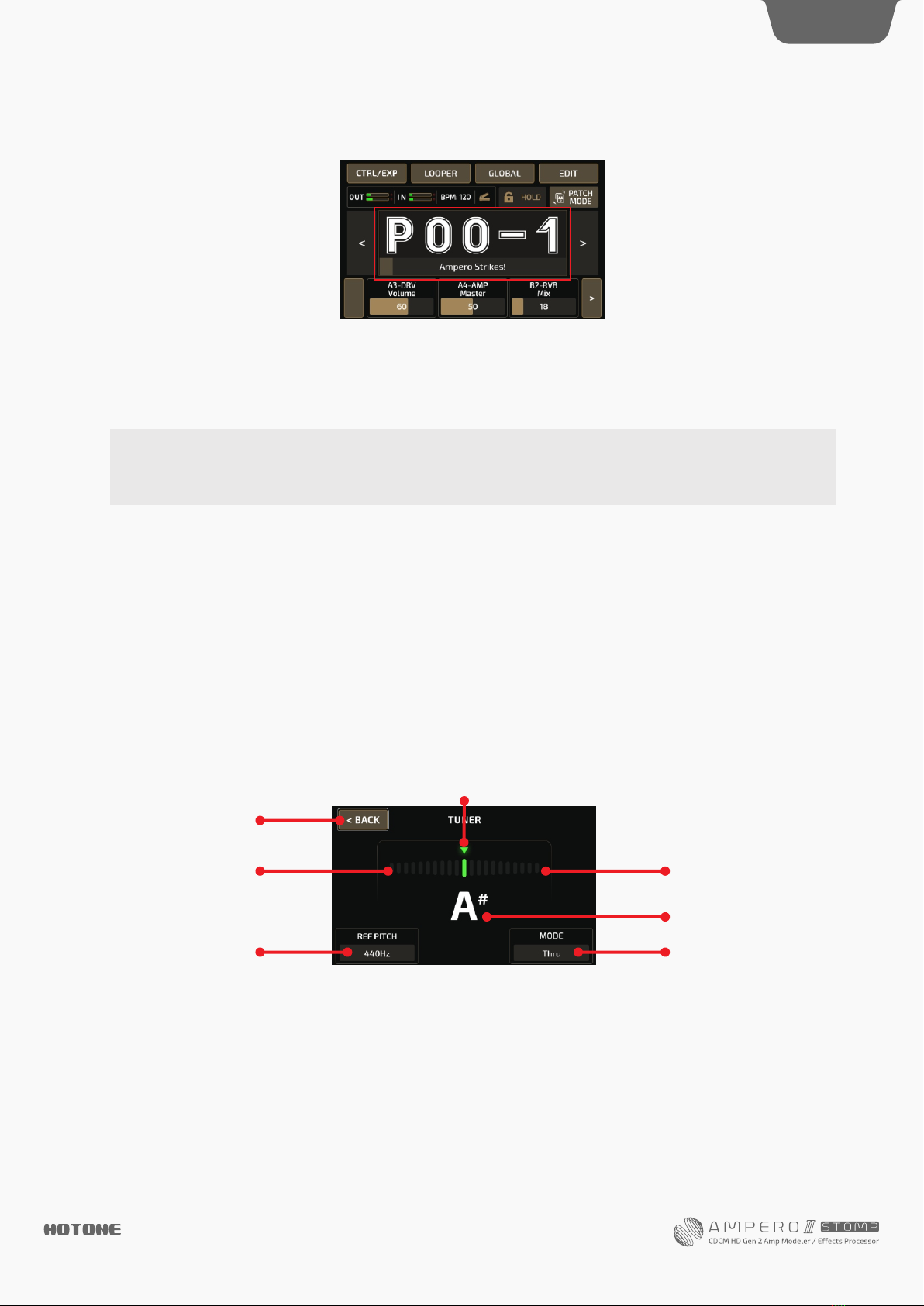
Main Display Screen
Using the Interface
Tools
Tuner
Looper
Unit Mode
Bypass
Customizing Your Ampero II Stomp
EDIT
Effects Chains Menu
Input Node Setup
Output Node Setup
Effects Chain Types
Using Effects Chain Templates
Split/Mixer Node Settings
Save Effects Chain Templates
Module/Effect Menu
Move, Swap, Copy, Paste and Delete Modules
Patch Tempo And Patch Volume
Tap Tempo And Tap Divide
Using FX Loop
CTRL/EXP
Current Settings
FS Settings
Quick Access Para
EXP Settings
Calibrate
SAVE
Patch Management
GLOBAL
I/O
USB Audio
Advanced USB Audio Interface Function Guide
Controls
MIDI Settings
Global EQ
Display
About
Factory Reset
Suggested Setups
Using with your instrument and amp
Connecting to your amp's RETURN or Power Amp
(Loudster)/FRFR cabinet INPUT
Connecting pedalboards
Connecting your mixer, interface, headphones, and
other equipment
Connecting to your computer as an audio interface
Using the AUX IN line
The Editor
Effects List
Effect Models List
DYN
FREQ
WAH
DRV
AMP
PRE AMP
CAB
IR
EQ
MOD
DLY
RVB
FX SND/FX RTN/FX LOOP
VOL
MIDI Control Information List
Troubleshooting
Technical Specifications
·······································1
··········································1
······································2
··········································3
··································5
·····························6
·······························7
···········································8
··········································8
·········································9
·····································10
········································10
················11
··········································11
· · · · · · · · · · · · · · · · · · · · · · · · · · · · 1 1
·······························13
······························14
·····························14
· · · · · · · · · · · · · · · · · · · · · 1 6
························16
· · · · · · · · · · · · · · · · · · · · · 1 8
· · · · · · · · · · · · · · · · · · · · · · · · · · · · 1 8
· · · · · · · · 1 9
· · · · · · · · · · · · · · · · · · · · 2 1
························21
··································22
· · · · · · · · · · · · · · · · · · · · · · · · · · · · · · · · · · · · · 2 4
······························24
··································24
·····························25
··································26
····································27
·········································28
· · · · · · · · · · · · · · · · · · · · · · · · · · · · · 2 8
·······································30
··········································30
···································31
······32
·····································33
································34
····································35
······································36
·······································36
··································36
······························37
························37
······················37
··························38
·································39
· · · · 3 9
· · · · · · · · · · · · · · · · · · · · · · · · · · · · 4 0
·····································40
····································41
· · · · · · · · · · · · · · · · · · · · · · · · · · · · · · 4 1
·······································41
·······································43
· · · · · · · · · · · · · · · · · · · · · · · · · · · · · · · · · · · · · · · 4 9
· · · · · · · · · · · · · · · · · · · · · · · · · · · · · · · · · · · · · · · 5 0
········································54
· · · · · · · · · · · · · · · · · · · · · · · · · · · · · · · · · · · · · 6 7
········································79
··········································83
··········································84
········································85
·········································89
·········································95
· · · · · · · · · · · · · · · · · · · · · · · 9 6
·······································96
· · · · · · · · · · · · · · · · · · · · · · 9 7
································99
· · · · · · · · · · · · · · · · · · · · · · · 1 0 0
DES I GN IN S PIRATION