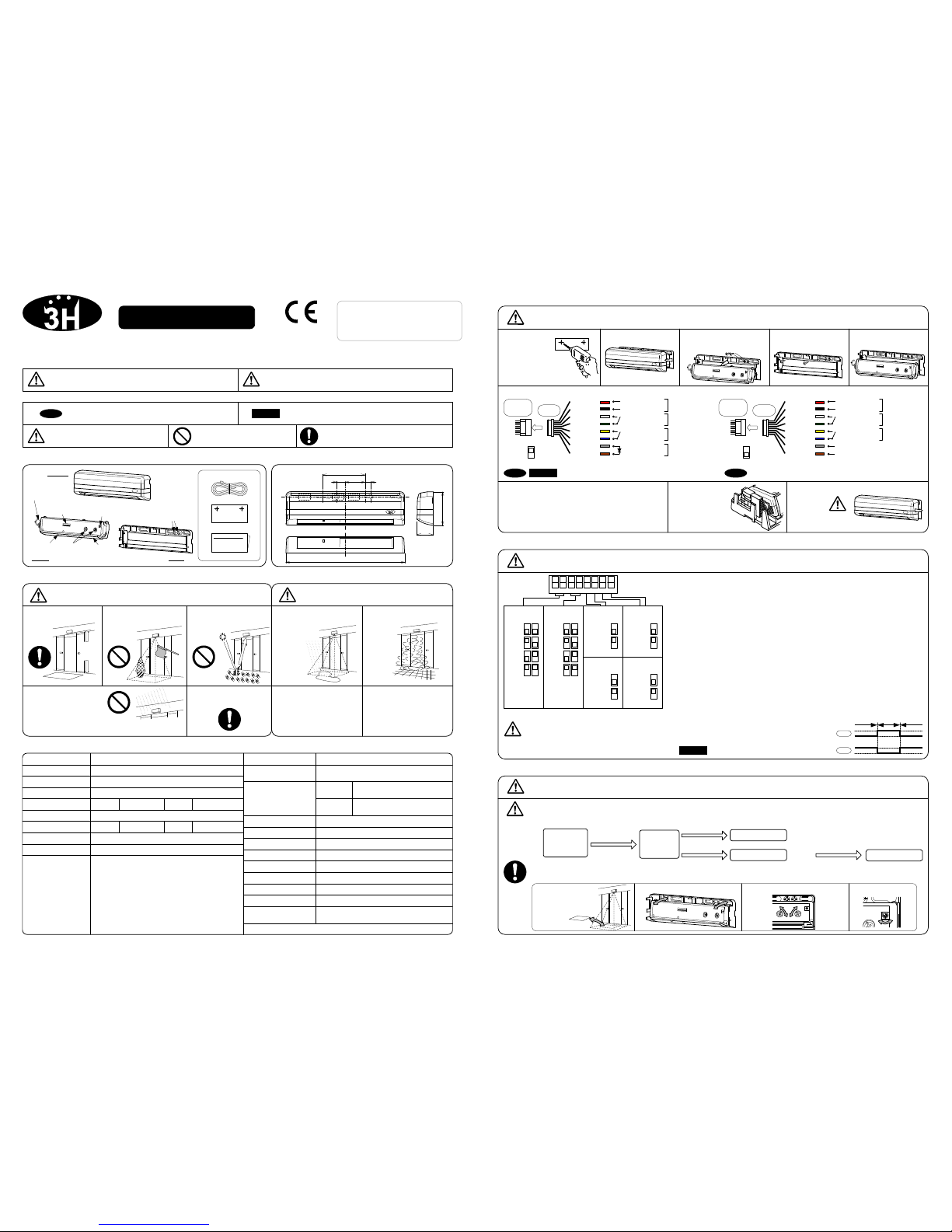
Hotron 3H-IR14C User manual

EN16005
Note
EN16005
8
OFF
CAUTION
CAUTION
WARNING
CAUTION
■Other symbols to be aware of.
Disregarding this symbol may result in injury
or damage to equipment.
Disregarding this symbol may result in
serious injury or death.
This symbol shows a situation
which should be avoided.This symbol shows an instruction which
must be followed.
This symbol shows a situation which
you should be aware of.
WARNING CAUTION
■The symbols below indicate dangers.
2. Remove the
Cover.
User Manual 3H-IR14C
Motion and Presence Sensor
Before using this sensor, read this user manual in detail.
During the lifetime of the product, keep the manual and refer it when needed.
3. MOUNTING PRECAUTIONS
To prevent malfunction mount as indicated.
1. Mount lower than 3m
5. Install in vibration free
environment
4. Mount where rain or
snow will not fall directly
on unit.
1. Accumulation of snow or
water on the floor.
3. Mount where no direct
and reflected sunlight
shine onto the sensor
2. Environment is humid or
steamy.
Cover
1. DESCRIPTION
User Manual
Accessories
Mounting Template
Cable
Body Base
3.0m
9. Place the Cover on sensor and wipe the
sensor clean.
Be careful not to move the sensor
Body when attaching the Cover.
8. House the Connector
in the space provided.
1. Determine the
mounting position
of the device and
attach the Mounting
Template. Drill the
mounting and wiring
holes.
5. MOUNTING & WIRING INFORMATION
Drilling may cause electric shock.
Be careful of hidden wires inside the door engine cover.
7. Set the following parameters
6-1. Wiring to a door controller that can test the sensor.
4. Install the Base with
the Mounting Screws. 5. Attach the Body to the
Base.
3. Remove the Mounting
Screws and the Body from the
Base .
6. DIP SWITCH SETTINGS
7. APPLYING POWER
If the sensor is exposed to excessive rain or snow,
protect it with a Hotron weather cover.
In the following cases, the sensor may
detect without the presence of a person
3. Objects placed in the
detection area. 4. Pets / Animals enter the
detection area.
③Safety Output
Refer to section 11. TIMING CHART OF EVENTS for full details on Safety Output.
⑤Monitor Mode
Set to “Snow”in instances where false door activations can result from blowing snow,
leaves or rubbish in the detection zone. It should be noted that sensitivity to detecting
pedestrians may also be reduced.
①Quantity of Detection Rows
The number of rows of detection can be set to 4, 3, 2 or 1 depending on detection area
required.
②Frequency
When more than two sensors are installed in close proximity to each other, select
different frequency setting for each sensors to prevent cross interference.
It will take approximately 6s for dip
switch setting changes to take effect.
If you carry out the following when the power is turned on, the sensor will detect for 30s.
Before turning on the power, wire the door controller to the sensor.
No moving object
Power-
on/Reset
Presence detection
If there is a moving object in detection area after Power-on / reset, the sensor will be in motion detection mode.
If there is no moving object in detection area after Power-on / reset, the sensor will be in presence detection mode.
Moving object Motion detection
5 s
No moving object
5 s
Remove
moving
object Presence detection
Motion
Detection
2 s
⑥TEST Input
When connected to a door controller without a TEST
Input, set to “OFF”. When connected to a door
controller with the TEST Input, set to “ON”
Refer to section 11. TIMING CHART OF EVENTS.
Place or remove a
mat in the detection
area.
Adjust the angle of Body. Adjust the width of the detection area. Adjust the sensitivity.
Default Setting:
☆
☆
①Quantity of
Detection Rows
R4
R3
R2
R1
1 2
☆
⑤Monitor
Mode
Normal
7
12345678
Snow
COMPLIED STANDARDS
DIN18650-1:2010
EN 12978:2003 +A1:2009
EN 16005:2012
EC type examination No. **** ********
☆
②Frequency
A
B
C
D
3 4
Setting required to conform with EN16005.
Special attention is required when this symbol is
shown.
2. Ensure no moving
objects are in the detection
area
6-2. Wiring to a door controller that cannot test the sensor.
Set “TEST Input”dip switch setting 8 to “ON”
Ref section 6. DIP SWITCH SETTINGS.Set “TEST Input”dip switch setting 8 to “OFF”
Ref section 6. DIP SWITCH SETTINGS.
Mounting Screws
(2 pcs.)
Potentiometer
(Sensitivity Volume)
Connector
LED
Indicator Area
Mask Detection
Window
Dip
Switch
4. TECHNICAL SPECIFICATIONS
Specification may change without prior notice.
0 to 5[degrees] R4~R1
Normal / Snow
4 Frequencies
2 [s]
Wide / Narrow
Installation Height
Sensitivity adjustment
3.0 [m]
Available
Presence Timer
Depth adjustment Angle Row
Width adjustment
Monitor mode
Frequency
Model Name 3H-IR14C AC12V : 1.1[VA]Max AC24V : 1.3[VA]Max
DC12V : 70 [mA]Max DC24V : 40 [mA]Max
Standby (Green)
R3,R4 Detecting (Blue)
R1,R2 Detecting (Red)
Door movement is detected (Orange)
Indicates a change of dip switch settings
(Fast flashing Orange )
Internal Sensor Error (Fast flashing Green/Red )
Reflected infrared signal from the floor is very low
(Flashing Green/Red )
Supply Voltage
Power Consumption
Output
AC/DC 12~24 [V]±10% 50/60 [Hz]
S : Silver , BL : Black
Output Holding Time
LED Indicator
Operating Temperature
Weight
Color
Approx 180 [g]
-20 ~ +60 [℃]
Approx 0.5 [s]
2. EXTERNAL DIMENSIONS
Active Infrared ReflectionDetection Method
[mm]
Form A Relay Contact
DC50[V] 0.1[A] (Resistance load)
Form A Relay Contact
DC50[V] 0.1[A] (Resistance load)
Safety
(R1,R2)
Activation
(R2,R3,R4)
Below 80 [%]
DC24V:6 [mA] Max
TEST Input
Operating humidity
Category 2 , performance level D according to EN
ISO 13849-1:2008
IP Rate IP54 (With Base)
0.1 ~ 0.2 [s]
Response Time
30 [s]
R1,R2 R3,R4
210
15
75(Standard Mounting Pitch)
35 10
28.5
59
section 6. DIP SWITCH SETTINGS
section 8. ADJUSTING DETECTION PATTERN
section 9. ADJUSTING SENSITIVITY
section 10. VERIFICATION OF OPERATION
section 11. TIMING CHART OF EVENTS
☆
⑥TEST Input
OFF
8
ON
③Safety
Output
④Activation
Output
☆N.O.
5
N.C.
☆N.O.
6
N.C.
④Activation Output
Refer to section 11. TIMING CHART OF EVENTS for full details on Activation
Output.
To comply with EN16005 set to “ON”.
8
ON
ON
Without
TEST
With
TEST
0v
OFF
Without
TEST
0v
Note
EN16005Note
Sensor’s
Cable Cable Red
Black
White
Green
Yellow
Gray(+)
Activation
Output
AC/DC
12~24V ±10%
Safety
Output
N.O./N.C.
Power
(Non Pole)
TEST Input
TEST Input (+)
TEST Input (-)
Blue
Brown(-)
N.O./N.C.
Sensor’s
Cable Cable Red
Black
White
Green
Yellow
Gray(+)
Activation
Output
AC/DC
12~24V ±10%
Safety
Output
Power
(Non Pole)
Blue
Brown(-) Do not connect
Do not connect
N.O./N.C.
N.O./N.C.
Set in a manner suitable for operation.

CAUTION
MP-10191 '16.06
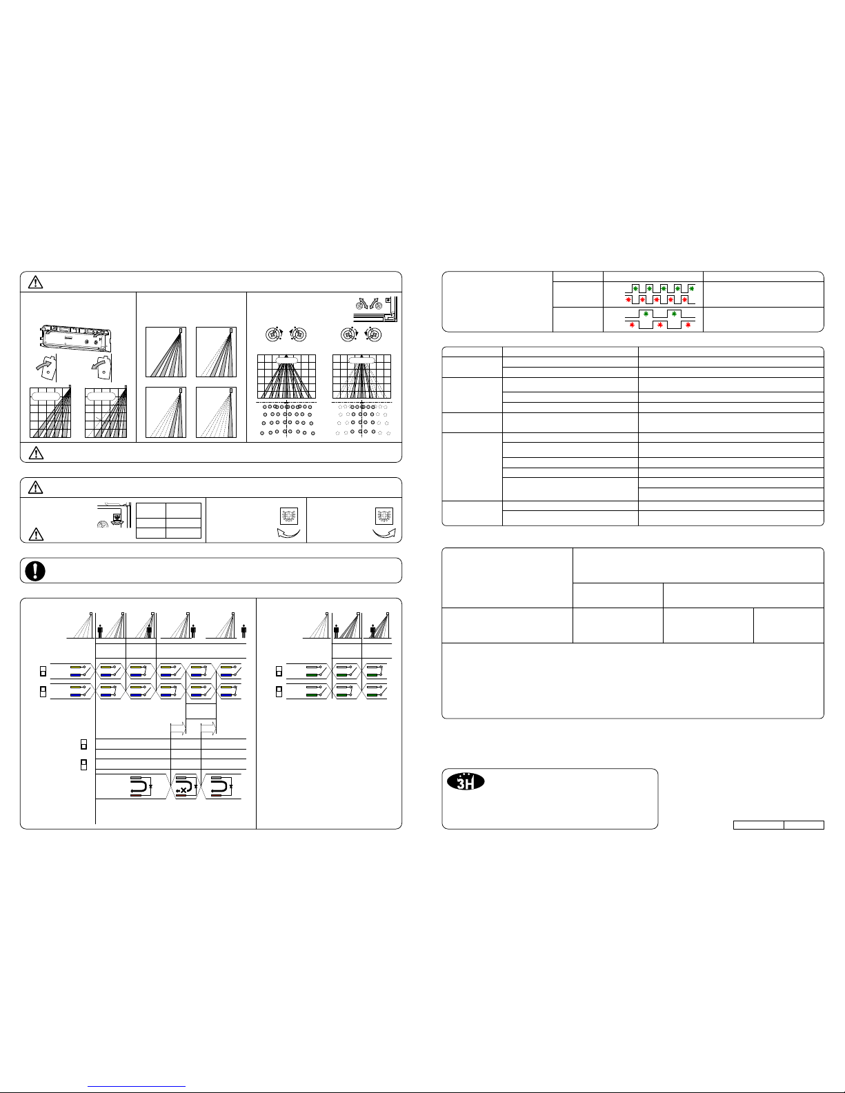
Adjust the detection pattern to either
0°or +5°by moving the sensor body as
illustrated.
9. ADJUSTING SENSITIVITY
2. If the sensor does not
detect a person entering
the detection area,
increase the sensitivity. After rechecking, if there is still a problem, please contact us or your dealer.
Reduce the detection area. Remove the moving object.
Problem Possible Cause Solution
Door opens and
closes for no apparent
reason (Ghosting) The sensor detects the movement of the door. Adjust the detection depth away from the door.
Door does not
operate
Door operates
intermittently
Door operate by itself
Tighten or reconnect the connector.
Apply proper voltage to the sensor. (AC/DC 12~24V)
Dust, frost or water droplet are on the sensor
lens. Wipe the Detection Window clean and install a weather cover if
necessary.
Sensitivity too low.
Inappropriate detection area.
Increase the sensitivity.
Adjust the detection pattern.
Object moving in the detection area.
Detection area is too far from the door, causing
detection of passing pedestrians.
Sensitivity too high. Decrease the sensitivity.
Another sensor is installed in close proximity. Ensure that the frequency setting of each sensor is not the same.
Addition or removal of a mat・Falling snow or
footprints in snow. Re-power the sensor.
Connection failure.
Incorrect power supply voltage.
Reduce the detection area.
13. TROUBLESHOOTING
< Disclaimer >
The manufacturer cannot be held responsible for below.
1. Misinterpretation of the installation instructions, miss
connection, negligence, sensor modification and
inappropriate installation.
2. Damage caused by inappropriate transportation.
3. Accidents or damages caused by fire, pollution, abnormal
voltage, earthquake, thunderstorm, wind, floods and other
acts of providence.
4. Losses of business profits, business interruptions, business
information losses and other financial losses caused by using
the sensor or malfunction of the sensor.
5. Amount of compensation beyond sellingprice inall cases.
Set Monitor Mode to "Snow"
3. If the sensor detects
even though no one is
in the detection area,
decrease the
sensitivity.
1. Set the appropriate
sensitivity setting for the
mounting height of the sensor.
3. Width adjustment
8. ADJUSTING THE DETECTION PATTERN
Adjust the detection width by turning
Area Mask with a screwdriver.
2. Depth adjustment –Number of
Rows of Detection
1. Depth Adjustment –Sensor Body
The detection range will vary depending on the installation environment, object detected and sensor settings (clothes and floor material as
well as sensor sensitivity settings will all have an effect)
Section 6. DIP SWITCH SETTINGS
Delete or add rows of detection
Ensure that the inner row of detection does not detect door movement
Narrow
Door
Door
After installation and sensor setting adjustment, walk test the sensor to ensure that the detection area is as required.
If unreliable detection or false door activations occur then re-adjust the sensor detection range and sensitivity settings.
10. VERIFICATION OF OPERATION
[m]
Wide
Technical problems with the
3H-IR14C sensor are indicated by a
flashing Green/Red LED. The
frequency of flashing indicates the
type of problem.
12. SELF DIAGNOSTICS ERRORS
4 Rows ON 3 Rows ON
2 Rows ON 1 Rows ON
26 Dublin Street (2nd Floor), Carlow, Ireland
URL: http://www.hotron.com
Fax: +353-(0)59-9140543
Phone: +353-(0)59-9140345
1-11-26 Hyakunin-Cho, Shinjuku-Ku, Tokyo, Japan
URL: http://www.hotron.com
Fax: +81-(0)3-5330-9222
Phone: +81-(0)3-5330-9221
Manufacturer
HOTRON CO.,LTD. SALES Europe
Hotron Ireland Ltd.
CAUTION
Non-
Detection
Power
OFF
1234
Detection Non-Detection
1. Safety Output Row 1, 2 / TEST Input
1234
Red
Green
Red
Green
Compiler of Technical File (EC Community) Description of Product:
Directives Fulfilled:
Above EC Type Directives Certified by:
Harmonized Standards Used: Other Technical Standards Used:
Declaration made by Date
Location of Declaration
Door opens and
remains in the open
position
Internal sensor error.
Reflection of the transmitted infrared signal from
the floor is too low. Increase the sensitivity.
Replace the sensor.
Replace the sensor
The sensor sensitivity setting is too low.
Fast
Slow
Flash Frequency LED Cause
14. EC DECLARATION OF CONFORMITY
3H-IR14C Combined motion and presence detection sensor for the activation and safety
of automatic doors.
Technology used is Active Infrared Technology.
David Morgan / Hotron Ireland Ltd
26 Dublin Street, Carlow, Ireland
Ph: +353-(0)59-9140345
Fax: +353-(0)59-9140543
EN ISO 13849-1:2008 DIN 18650-1:2010
EN 16005:2012
TUV NORD CERT GmbH
30519 Hannover, Germany
Identification No: 0044
Teruya Morimoto
Director Quality Assurance Honda Electron Co. Ltd
1-23-19 Asahi-cho,Machida-City,
Tokyo, Japan
************
11. TIMING CHART OF EVENTS
5°
[0°]
1.0
2.0
0
1.0
2.0
3.0
1.0
2.0
[+5°]
[m]
0
1.0
2.0
3.0
1.02.0 01.0 2.0
Wide
1.02.0 01.0 2.0
Narrow
H L
M
H L
M
N.O.
5
N.C.
Blue
Yellow
1234 1234 1234 1234
Blue
Yellow
TEST
Response
Detection as
response to
TEST
TEST Non-TEST TEST
Non-TEST TEST Non-TEST
OFF
8
ON
Brown(-)
Gray(+)
Supplying DC12 to 24V,
make current flow from
Gray to Brown.
Break the
current flow
on test state.
T1 : 10±1ms App.
T2 : 11±1ms App.
T2T1
2. Activation Output Row 2, 3, 4
Non-
Detection
Power
OFF
1234
Detection
N.O.
6
N.C.
Green
White
Green
White
1234
DIRECTIVE 2006/42/EC
DIN 18650-1:2010 Powered pedestrian doors Part 1: Product requirements chapter 5.7.4
EN 12978:2003 +A1:2009 Industrial, commercial and garage doors and gates - safety devices for power operated doors and gates
- Requirements and test methods
EN 62061:2005 Functional safety of electrical/electronic/programmable electronic safety-related systems
EN ISO 13849-1:2008 Safety of machinery - Safety-related parts of control systems.
EN 16005:2012
EC type examination No. *************
2.0 ~2.5
2.5 ~3.0
L ~M
M ~H
Criterion of
sensitivity
Height
[m]
Adjust the sensitivity that is appropriate to the installation environment.
Table of contents
Other Hotron Accessories manuals
Popular Accessories manuals by other brands

Celsius
Celsius CELQEB-LS operating instructions

StarTech.com
StarTech.com ST128HD20 quick start guide

Prolitec
Prolitec AirQ 270 TT manual

MICRO-EPSILON
MICRO-EPSILON ILD1700 user manual

Dorner
Dorner AquaPruf 7400 Ultimate CE Series Installation, Maintenance, and Parts Manual

Vega
Vega VEGAPULS 69 operating instructions

Robern
Robern VDELECTRIC installation instructions

Dynasty
Dynasty Energy saver user manual

Fisher Scientific
Fisher Scientific Isotemp 500 Series instruction manual

Bogen
Bogen NR-100 Specifications

Bühler technologies
Bühler technologies ENK 300-15-4-0.75kW-50Hz Installation and operation instruction

Sonifex
Sonifex SignalLED Series User handbook