Hougen-Ogura 0755101 User manual

75005 PUNCH PRO™
ELECTRO-HYDRAULIC HOLE PUNCHER
operator’s manual
COVERS HOLE PUNCHER PART NUMBERS 0755101 & 755201

2
IMPORTANT SAFETY INSTRUCTIONS
WARNING: When using electric tools, basic safety precautions should always be followed to reduce the
risk of re, electric shock, and personal injury, including the following.
5. Consider Work Area Environment
Do not expose tool to rain
Do not use tool in damp or wet
locations. Keep work area well lit.
Donotusetoolinpresenceofammable
liquids or gases.
6. Guard Against Electric Shock
Preventbodycontactwithgroundedsur
faces. For example: pipes, radiators, ranges,
refrigerator enclosures.
7. Keep Children Away
Do not let visitors contact tool or extension
cord.Allvisitorsshouldbekeptawayfrom
work area.
8. Store Idle Tools
Whennotinuse,toolsshouldbestoredina
dryhighorlocked-upplace-outofreachof
children.
9. Do Not Force Tool
Itwilldothejobbetterandsaferattheratefor
whichitwasintended.
10. Use Right Tool
Donotforcesmalltoolorattachmenttodothe
jobofaheavy-dutytool.Donotusetoolfor
purpose not intended.
11. Dress Properly
Donotwearlooseclothingorjewelry.Theycan
becaughtinmovingparts.Rubberglovesand
nonskidfootweararerecommendedwhen
workingoutdoors.Wearprotectivehaircovering
tocontainlonghair.
12. Always wear safety glasses or goggles.
13. Do Not Abuse Cord.
Nevercarrytoolbycordoryankitto
disconnect from receptacle. Keep cord from
heat,oilandsharpedges.
2b. Extension Cords
Useonly3-wireextensioncordsthathave
3-pronggroundingtypeplugsand3-pole
receptaclesthatacceptthetool’splug.
Replace or repair damaged cords.
Makesuretheconductorsizeislargeenough
to prevent excessive voltage drop will cause
lossofpowerandpossiblemotordamage
3. FOR ALL DOUBLE-INSULATED TOOLS
Whenservicinguseonlyidenticalreplace-
ment parts.
4. Keep Work Area Clean
Clutteredareasandbenchesinviteinjuries.
1. READ ALL INSTRUCTIONS
2. Grounding Instructions
2a. Thistoolshouldbegroundedwhileinuseto
protecttheoperatorfromelectricshock.The
toolisequippedwitha3-conductorcordand
3-pronggroundingtypeplugtottheproper
groundingtypereceptacle.Thegreen(or
greenandyellow)conductorinthecordisthe
groundingwire.Neverconnectthegreenor
greenandyellowwiretoaliveterminal.If
yourunitisforuseon115V,ithasaplugthat
lookslikethatshowninsketch(A).Anadapter,
seesketches(B)and(C),isavailablefor
connectingsketch(A)typeplugsto2-prong
receptacles.Thegreen-coloredrigidear,lug,or
thelikeextendingfromtheadaptermustbe
connectedtoapermanentground,suchasa
properlygroundedoutletbox.
NOTE: Use of a grounding adapter is pro-
hibited in Canada by Part 1 of the Canadian
Electrical Code.
TEEFNIDROCFOHTGNELTEEFNIDROCFOHTGNEL TEEFNIDROCFOHTGNEL TEEFNIDROCFOHTGNELTEEFNIDROCFOHTGNEL
V511
)spmA( .TF52.TF05.TF001.TF051.TF002.TF052.TF003
6-5 8161412101018
8-6 816121010186
01-8 81412101886
21-01 6141018866
41-21 6121018666
61-41 6121018664

3
TheHougen-OguraElectro-hydraulicHolePuncher
isanintegratedunit,containingtheelectric
motor,hydraulicpump,and"C"-framepunching
unit.Ituseshydraulicpowertoforcethepunch
throughtheworkpiece,andastrongspringtoreturn
thepunchpistontoits"home"position.Thepatented
designincludesanautomaticvalvethatreleasesthe
hydraulicpressurewhenthepunchpistonisatthe
bottomofitsstroke.Theautomaticvalveremains
openuntilthepunchpistonhasfullyreturnedtothe
homeposition.
Asaresultofthisdesign,thepistonwillnotreturnto
itshomepositionautomaticallyunlessthefullstroke
hasbeencompleted.Also,thepunchwillnotbegin
anotherstrokeunlessthepunchhasfullyreturned
tothehomeposition,resettingtheautomaticvalve.
Toallowthepunchpistontobemanuallyreturned
intheeventthatthepunchcycleisstoppedpriorto
completion, a manual return valve is provided.
PRINCIPLES OF OPERATION
CAUTION! To prevent electric
shock,donotusepowertools
nearwetareas,orwherepower
toolmaybecomewet.
Alwaysweareyeprotectionwhile
usingpunchingtools,orinthe
vicinityofpunching.
CAUTION!Theslugisejectedat
theendofthepunch.Donotaim
theunitsothatejectedslugmay
hitsomeonearound,orbelow
you.
SAFETY FIRST
CAUTION!Riskofpinchingor
crushing.Keepawayfrommov-
ingpartswhenunitisinuse.
Oil Port
Manual Return
Valve
“C” Frame
Hole Locator
Gauge
Work Stand
Die
Punch
Aux. Handle

4
Read,understandandfollowallsafetyinstructionsand
operatingprocedures.Ifyoudonotunderstandthe
instructions or if conditions are not correct for proper
operation,donotoperatethemachine.Consultyour
supervisororotherresponsibleperson.
*Checkthatthetriggerswitchisnotlockedon.
*Checkthatthemanualreturnvalveisclosed.
*Makesurethattheproperpunchanddieareinstalled
correctly.SeeDie Selection and Proper Punches and
Dies on next page.
*Ifyouareusingtheholelocatorgauge,adjustittothe
proper distance. See Hole Locator Gauge Adjustment
on next page.
OPERATING PROCEDURES
*Plugthepowercordintotheproperpowersupply.
*Positionthepuncherattheproperlocationonthe
workpieceusingtheholelocatorgageorbylocatingthe
pointontheendofthepunchintoacenterpunchmarkon
thepiece.
Witheverythinginproperorder,theswitchcanbeactivated
tostarttheelectricmotor.Thepunchpistonwillmoveout
andpushthepunchthroughthematerial.Keeptheswitch
onuntilthepunchhasreachedtheendofitsstrokeand
stops.Releasetheswitch.Theautomaticreturnvalvewill
openattheendofthestrokeallowingthepunchpistonto
retracttoitshomeposition.Thepunchpistonmustreturn
completelybeforeanotherholecanbepunched.
Ifthepunchstopsinthemidstofitsstrokeordoesnot
comeoutofthematerial,openthemanualreturnvalve.
Oncethepunchpistonhasreturnedtoitshomeposition,
tightenthemanualreturnvalve.
Althoughthefootswitchisguardedagainstinadvertent
operation,itisbesttopositionthefootpedalawayfrom
normalstandingposition.Placeitinapositionthat
requiresdeliberateefforttoreachandactivatetheswitch.
Thetriggerswitchshouldbelockedononlywhenready
topunch.Releasethetriggerswitchimmediatelyafter
punchingtopreventoperationbyinadvertentactuationof
thefootswitch.
INSTRUCTIONS -- FOOT SWITCH
WARNING! Failure to check punch retaining nut periodically during use, can result in
personal injury or damage to the unit could occur.
75005 CONTENTS
HydraulicOil 75377
13/16"DiameterPunch 75539
13/16"DiameterDie-TypeB-Formaterial1/4"to3/8" 75556
13/16"DiameterDie-TypeA-Formaterial1/8"to1/4" 75555
Pin Spanner 75772
HookTypeSpannerWrench 75773
FootSwitch(115V) 75110
FootSwitch(230V) 76479
FootSwitch(230V,TypeI) 76480
Work Stand 75311
M4HexKey 75743
M5HexKey 75744
M6HexKey 75745
M8HexKey 75746
M10HexKey 75747

5
Allmodelscanbeusedwithanaccessoryworkstandfor
benchortablemountingoftheHolePuncher.Thestand
isstandardwithallmodels.Toinstallthestand,rst
unplugthepowercord.,thenmounttheunittothestand
withthesuppliedhardware.
Whenusingthestand,periodicallychecktomakesurethat
thepunchedmaterial(slugs)arenotstackingupbetween
theexitholeinthe"C"-frameandthestand.Keepthisarea
clear of accumulated slugs.
USING THE WORK STAND
SELECTING PROPER DIES
Properdieselectionisessential.Otherthantheobvious
necessityofmatchingshapedpunchesanddies,thereare
twootherbasicselectionfactorsthatmustbeconsidered.
Therstisdieclearance.Differentmaterialtypesand
differentmaterialthicknessesrequiredifferentclearances
betweenthepunchanddie.Inordertomaintainthebest
possibleholewhileremainingwithinthetonnage
capacityofthemachine,itisessentialtochoosethedie
withtheproperclearance.Thesecondisthedieangle.
Moststructuralshapescanbepunchedwiththestandard
atdies,but"I"-beamsandmostchannelswhich
havea2-in-12taperrequiretheuseofspecial
9-1/2degreeangleddies.Carandshipchannel
angesandotherstructuralshapeswitha2degree
tapercanbepunchedwithatdies.Materialswith
aangetaperoflessthan5degreescanalsobe
punchedwiththeatdie,however,theholewillbe
slightlyangled.Refertospecicinformationand
tableswithinthismanualfortheproperpunchand
diecombination.
TheHolelocatorGaugecanbesettoholdtheHole
Punchesataconstantdistancefromtheedgeofthe
workpiece.Thegaugeisheldinplacebyoneortwosocket
headcapsscrews.Beforemakinganyadjustment,
rst,unplugthepowercord.Toadjustthepositionofthe
gauge,loosenthecapscrew(s),tapthegaugeintothe
desiredpositionandretightenthecapscrew(s).
HOLE LOCATOR GAUGE ADJUSTMENT
Hougen-Ogura Punches are designed to be used in
Structural Steel. If used in harder or higher tensile
strength materials, performance will be impeded and
serious damaged could occur to your unit.

67
74
90
25
3
58 57 33-14
33-15 33-2
43 60
37 40
33-3
33-6
33-1
33-7
33-8
33-9
65
81
80
65
33-17
33-19
88
59
58
33-7
33-8
33-9
33-18
33-19 82 65
33-4
33-16
33-21
86
33-22
33-12
33-11
33-5
69
70
33-20
30
74
29
28
61 32
56
56
31
72
9
44
8
45
45
1
73
73
74
74
75
75
6
48 47
71
10
71 10 7 34 35 15
52
24
55
13
68
26
55
27
36
4 10
11
12
54
66
22
22
22
2
16
21-2
18
17
19
20
53
38
14
49
50
42
41
39
23
23
6
75005 EXPLODED VIEW

PARTS LIST - 75005
7
Item Part # Description Qty
175260 “C” Frame 1
275323 Cylinderw/chamfers 1
375262 Pump Housing 1
475263A PunchPiston 1
675264 Hole Locator 1
775265 Stripper 2
875539 Punch13/16”Dia. 1
975555 Die13/16”AType 1
10 75266 Release Valve 1
11 75267 Valve Return Spring 1
12 75268 Stop Plate 1
13 75269 Valve Release Spring 1
14 75046 Return Valve 1
15 75047 Return Lever 1
16 75270(A-J) Pump Piston 3
17 75325 RubberPackingw/groove 3
18 75050 CheckValve 3
19 75326 O-Ring 3
20 75052 CheckValveSpring 3
21-1 75340 Piston Return Spring 3
21-2 75341 Piston Return Spring 3
22 75054 Magnet 3
23 75271 Spacer 2
24 75272 O-Ring 1
25 75273 Gasket 1
26 75274 PunchReturnSpring 1
27 75275 PunchPistonKey 1
28 75136 Screw Bladder 1
29 75137 Oil Bladder 1
30 75138 Bladder Retaining Screw 1
31 75063 PunchHandle 1
32 75276 Bladder Cover 1
33-1 75277 Motor Housing 1
33-2 75278 Field(115V) 1
76475 Field(230V) 1
33-3 75279 Armature(115V) 1
76474 Armature(230V) 1
33-4 75280 SwitchCover 1
33-5 75365 Switch 1
33-6 75281 Ball Bearing 1
33-7 75282 BrushCover 2
33-8 75283 CarbonBrush(Pair) 1
33-9 75284 BrushCap 2
33-11 75074 StrainRelief(115V) 1
76446 StrainRelief(230V) 1
33-12 75148 PowerCord(115V) 1
76476 PowerCord(230V) 1
76478 PowerCord(230V,TypeI) 1
33-14 75285 Hex Head Bolt 2
33-15 75150 HeliLockWasher 2
33-16 75286 Pan Head Screw 2
33-17 75287 MotorTopGrill 1
Item Part # Description Qty
33-18 75288 MotorSideGrill 1
33-19 75289 Pan Head Screw 4
33-20 75290 Adapter Plate 1
33-21 75291 SwitchBracketGasket 1
33-22 75292 Slotted Retainer 2
34 75293 Back up Ring 1
35 75294 Rod Seal Packing 1
36 75295 Packing 1
37 75296 Oil Seal 1
38 75085 O-Ring 1
39 75086 Ball Bearing 1
40 75297 Ball Bearing 1
41 75088 Roller Bearing 1
42 75298 Retaining Ring 1
43 75090 WasherSeal 1
44 75299A PunchRetainingNut 1
45 75300 Soc. Set Screw 1
47 75301 Soc. Head Screw 1
48 75302 FlatWasher 1
49 75303 Soc. Head Screw 8
50 75304 FlatWasher 8
51 75305 Spanner Nut 1
52 75306 Backup Ring 1
53 75100 Roll Pin 1
54 75105 FlatWasher 3
55 75307 Soc. Head Screw 3
56 75103 Soc. Head Screw 2
57 75236 Soc. Head Screw 1
58 75093 HeliLockWasher 5
59 75308 Soc. Head Screw 1
60 75107 Soc. Head Screw 1
61 75309 O Ring 1
65 75109 Rivet 10
66 75110 FootSwitch(115V) 1
76479 FootSwitch(230V) 1
76480 FootSwitch(230V,TypeI) 1
67 75311 Work Stand 1
68 75312 O Ring 2
69 75313 Soc. Head Screw 4
70 75097 FlatWasher 4
71 75314 Soc. Head Screw 4
72 75315 EyeBolt 1
73 75316 Soc. Head Screw 2
74 75155 HeliLockWasher 4
75 75317 FlatWasher 2
80 75033 Warning Tag 1
81 75034 Caution Tag 1
82 75031 Name Tag 1
86 75350 Pan Head Screw 1
88 75318 Soc. Set Screw 2
89 75247 Pan Head Screw 2
90 75226 Soc. Head Screw 1

PUNCHES AND DIES FOR 75005
8
Punch-Pro
™
— Model 75005
ROUND PUNCH MATERIAL DIE
Size Part
No. Thickness Style Size Part
No.
Nominal Actual Metric
7/16" .433 11mm 75532
>1/8 (.125) to 1/4 (.250)
10 to 3 GA. F, A, H Die 7/16 A 75541
>1/4 (.250)
to 3/8 (.375) F, A, H Die 7/16 B 75542
5/16 (.312)
max. C Die 7/16 C 75559
15/32" .472 12mm 75937
>1/8 (.125) to 1/4 (.250)
10 to 3 GA. F, A, H Die 15/32 A 75939
>1/4 (.250)
to 3/8 (.375) F, A, H Die 15/32 B 75940
5/16 (.312)
max. C Die 15/32 C 75941
1/2" .512 13mm 75533
>1/8 (.125) to 1/4 (.250)
10 to 3 GA. F, A, H Die 1/2 A 75543
>1/4 (.250)
to 3/8 (.375) F, A, H Die 1/2 B 75544
5/16 (.312)
max. C Die 1/2 C 75560
9/16" .551 14mm 75534
>1/8 (.125) to 1/4 (.250)
10 to 3 GA. F, A, H Die 9/16 A 75545
>1/4 (.250)
to 3/8 (.375) F, A, H Die 9/16 B 75546
5/16 (.312)
max. C Die 9/16 C 75561
5/8" .625 15.9mm 75535
>1/8 (.125) to 1/4 (.250)
10 to 3 GA. F, A, H Die 5/8 A 75547
>1/4 (.250)
to 3/8 (.375) F, A, H Die 5/8 B 75548
5/16 (.312)
max. C Die 5/8 C 75562
11/16" .688 17.5mm 75536
>1/8 (.125) to 1/4 (.250)
10 to 3 GA. F, A, H Die 11/16 A 75549
>1/4 (.250)
to 3/8 (.375) F, A, H Die 11/16 B 75550
5/16 (.312)
max. C Die 11/16 C 75563
23/32" .709 18mm 75938
>1/8 (.125) to 1/4 (.250)
10 to 3 GA. F, A, H Die 23/32 A 75942
>1/4 (.250)
to 3/8 (.375) F, A, H Die 23/32 B 75943
5/16 (.312)
max. C Die 23/32 C 75944
3/4" .750 19mm 75537
>1/8 (.125) to 1/4 (.250)
10 to 3 GA. F, A, H Die 3/4 A 75551
>1/4 (.250)
to 3/8 (.375) F, A, H Die 3/4 B 75552
5/16 (.312)
max. C Die 3/4 C 75564
25/32" .787 20mm 75538
>1/8 (.125) to 1/4 (.250)
10 to 3 GA. F, A, H Die 25/32 A 75553
>1/4 (.250)
to 3/8 (.375) F, A, H Die 25/32 B 75554
5/16 (.312)
max. C Die 25/32 C 75565
13/16" .812 20.6mm 75539
>1/8 (.125) to 1/4 (.250)
10 to 3 GA. F, A, H Die 13/16 A 75555
>1/4 (.250)
to 3/8 (.375) F, A, H Die 13/16 B 75556
5/16 (.312)
max. C Die 13/16 C 75566
7/8" .875 22.2mm 75540
>1/8 (.125) to 1/4 (.250)
10 to 3 GA. F, A, H Die 7/8 A 75557
>1/4 (.250)
to 3/8 (.375) F, A, H Die 7/8 B 75558
5/16 (.312)
max. C Die 7/8 C 75567
OBLONG PUNCH MATERIAL DIE
Size Part
No. Thickness Style Size Part
No.
Nominal Actual Metric
7/16"
x
5/8"
.433
x
.650
11mm
x
16.5mm
75690
>1/8 (.125) to 1/4 (.250)
10 to 3 GA. F, A, H Die 7/16 x 5/8 A 75694
>1/4 (.250)
to 3/8 (.375) F, A, H Die 7/16 x 5/8 B 75695
5/16 (.312)
max. C Die 7/16 x 5/8 C 75702
1/2"
x
3/4"
.512
x
.768
13mm
x
19.5mm
75691
>1/8 (.125) to 1/4 (.250)
10 to 3 GA. F, A, H Die 1/2 x 3/4 A 75696
>1/4 (.250)
to 3/8 (.375) F, A, H Die 1/2 x 3/4 B 75697
5/16 (.312)
max. C Die 1/2 x 3/4 C 75703
9/16"
x
13/16"
.551
x
.827
14mm
x
21mm
75692
>1/8 (.125) to 1/4 (.250)
10 to 3 GA. F, A, H Die 9/16 x 13/16 A 75698
>1/4 (.250)
to 3/8 (.375) F, A, H Die 9/16 x 13/16 B 75699
5/16 (.312)
max. C Die 9/16 x 13/16 C 75704
11/16"
x
13/16"
.709
x
.827
18mm
x
21mm
75693
>1/8 (.125) to 1/4 (.250)
10 to 3 GA. F, A, H Die 11/16 x 13/16 A 75700
>1/4 (.250)
to 3/8 (.375) F, A, H Die 11/16 x 13/16 B 75701

9
TROUBLE SHOOTING
MELBORP ESUAC NOITULOS
TUBSNURROTOM
SEODNOTSIPHCNUP
TUOEMOCTON
NEPOSIEVLAVNRUTERLAUNAM EVLAVNRUTERLAUNAMESOLC
TNEICIFFUSNISILIOLIODDA
DENRUTERTONSAHNOTSIP
EMOHSTIOTYLETELPMOC
,SPIHCLEETSOTEUDNOITISOP
EHTNOSIRBEDREHTOROTRID
REDLOH-HCNUPDESOPXE
.NOITISOP
DESOPXEMORFSIRBEDNAELC
FONOITROPREDLOH-HCNUP
NOTSIPHCNUPHSUP.DORNOTSIP
.NOITISOPEMOHSTIOTKCAB
SIGNIRPSNRUTERNOTSIPHCNUP
DORHCNUPNRUTEROTKAEWOOT
EHTYBDECIVRESENIHCAMEVAH
YROTCAF
SEMOCNOTSIPHCNUP
GNIHCNUPTUB,TUO
KAEWOOTSIREWOP
HCNUPOT
TONSIEVLAVNRUTERLAUNAM
DESOLCYLETELPMOC EVLAVNRUTERLAUNAMESOLC
SIRIAROTNEICIFFUSNISILIO
RIOVRESERNIDEPPART LIODDA
STRAPNOTSIPROPMUPLANRETNI
DEGAMADROYTRID,NROWERA
YLREPORPGNINOITCNUFTONDNA
EHTYBDECIVRESENIHCAMEVAH
YROTCAF
TONSEODROTOM
ROOPROETATOR
ROTOMFONOITATOR
TIUCRICREWOPNEPO ,DROCNOISNETXE,GULPKCEHC
REKAERBTIUCRIC
EGATLOVREPORPMIECRUOSREWOPKCEHC
PORDEGATLOVEVISSECXE
FOERASDROCNOISNETXE
EHTROFEZISERIWTNEICIFFUSNI
.DROCEHTFOHTGNEL
ROSDROCDEGAMADRONROW
.SEHSURBNOBRACNROW.SGULP
STRAPROTOMLANRETNIDEGAMAD
EHTYBDECIVRESENIHCAMEVAH
YROTCAF
NEEWTEBGNIKAELLIO
DNAEMARF"C"
NEEWTEBROREDNILYC
PMUPDNAREDNILYC
GNISUOH
THGITTONERASTLOBSTLOBNETHGIT
DEGAMADSITEKSAG EHTYBDECIVRESENIHCAMEVAH
YROTCAF
DNUORAGNIKAELLIO
MORFRONOTSIP
AERALANRETNI
SECAFRUSROSLAESLANRETNI
KCASRELEVELLIO.DEGAMADERA
NEKORBSI
EHTYBDECIVRESENIHCAMEVAH
YROTCAF
TONSEODHCNUP
FOTUOPIRTS
RETFAECEIPKROW
GNIHCNUP
NROWSIEIDROHCNUPECALPER
ROLAIRETAMROFEIDREPORPMI
SSENKCIHT
DNAHCNUPREPORPROFKCEHC
NOITCELESEID
HTOBREDNUTONSAWECEIPKROW
ROGNIDNIBSIDNASREPPIRTS
HCNUP
SILAIRETAMEHTTAHTERUSEKAM
GNIHCNUPEHTNIDETAESYLLUF
AERA

10
NOTE: The internal components of the pump and piston area have very close clearances and are sensitive
to damage from dust, dirt, contamination of the hydraulic uid or improper handling. The disassembly of the
pump housing requires special tools and training, and should be attempted by a qualied repair person. The
improper servicing of electrical components can lead to conditions that could cause serious injury.
ANY ATTEMPT BY UNAUTHORIZED PERSONNEL TO SERVICE THE INTERNAL COMPONENTS OF
THE PUMP AREA WILL VOID THE WARRANTY.
Inordertoinsuresmootheroperationandlongerlifeofyour
holepuncher,thefollowingmaintenanceshouldbedone
periodically,basedonuse.
1. Keepthemachineclean.Itisespeciallyimportantto
keeptheslidingportionofthepunchpistonfreefrommetal
chips,scale,dirt,dustorotherdebris.Tocleanthepunch
piston,turnontheswitchtomovethepunchpistonalmost
tothebottomofitsstroke.Ifnecessary,cyclethepunch
severaltimestodeterminewherethebottomofthestroke
is,andtocorrectlypositionthepunchpiston.
Unplugthepowercord.Wipeanydebrisfromtheex-
posedpartofthepunchpiston.
2. Regularlytightenallfastenersandreplaceany
worn components.
3. Checkpowercord,ifcrackedorfrayed,returnthe
machinetoanauthorizedrepaircenterfor
replacement.
4. Checkoillevel,carefullyusingtheprocedurebelow.
ADDING OIL
4. Carefullyopentheoilportbyremovingthesocket
headcapscrew.
5. Usingthesmallsqueezebottlesuppliedwiththe
HolePuncher,carefullyaddhydraulicoiltocompletely
llthereservoir.RocktheHolePuncherbackandforth
slightlyseveraltimestofreeanytrappedairbubbles,
thenaddadditionaloilifnecessary.
6. Replacethecapscrewandwipeupanyexcessoil.
7. CycletheHolePuncherseveraltimeswiththe
ManualreturnValveopen,andagainwiththevalve
closed,toworkanytrappedairoutofthesystem,
thenrepeattheaboveprocedure,makingsurethatthe
punchpistonisalmostatthebottomofthestroke
beforeremovingthecapscrewfromtheoilport.
8. Addadditionaloilasnecessary.Iftheunitwas
extremelylowonoil,itmaybenecessarytorepeat
theprocedureseveraltimes.
MAINTENANCE
HELPFUL HINTS FOR HOLE PUNCHING
Eachofthepunchesisprovidedwithasharppointatits
center.Iftheholelocationsarecenterpunched,thepoint
ontheendofthepunchmaybeusedto"nd"thecenter
punchedspot.
Also,foraccurateandeasypositioningofthepunchtoa
holelocation,theswitchcanbeintermittentlypulsedon
andofftojogthepunchdowntotheworksurface.
Ifthepositionisnotsatisfactory,openthemanualreturn
valvetoretractthepunchforanotherattempt.This
operationcanalsobeperformedwiththemanualreturn
valve"cracked"openslightlytopreventfullpunching
pressurefrombeingdeveloped.Inthismanner,the
punchcanbeeasilybroughtrightdowntothesurface
withoutbeginningtopunchthehole.Ifthelocationis
satisfactory,closethevalveandnishtheoperation.
Useofthecorrecthydraulicoilisessential.Approvedoils
areShell"TELLUSOil"andExxon"TERESSTIC"(Part
No.75377).Grade#32viscositymustbeused.Checkthe
unitspecications.Makesurethattheworkareaandall
equipmentarecleansothatnodirt,dustorotherforeign
materialcangetintothehydraulicoilorpumparea.
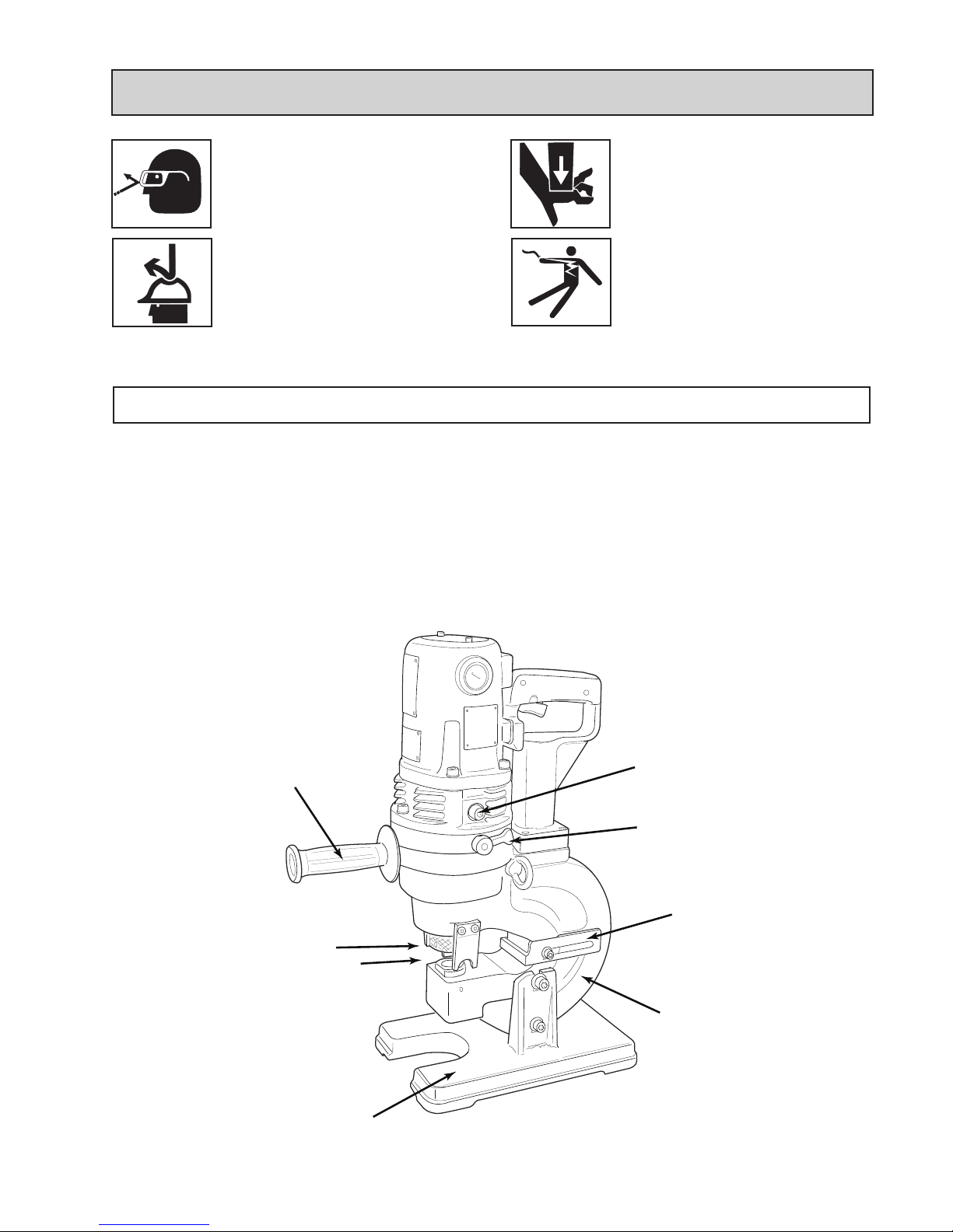
1. Locatethesocketheadcapscrewthatplugstheoilport.
Itisjustabovethemanualreturnleverontherighthand
sideoftheHolePuncher.
2. LaytheHolePuncheronitsleftsidesothattheoilport
is facing up.
3. Turnontheswitchtomovethepunchpistonalmost
tothebottomofitsstroke.Ifnecessary,cyclethepunch
severaltimestodeterminewherethebottomofthestroke
is,andtocorrectlypositionthepunchpiston.Inthisposi-
tion,themaximumamountofoilhasbeendrawnfromthe
pumpandthecorrectllcanbeobtained.
WARNING! Failure to check punch retaining nut periodically during use, can result in
personal injury or damage to your unit.
This manual suits for next models
2
Table of contents
Other Hougen-Ogura Power Tools manuals