Hoval TopGas classic 12 User manual

TopGas®classic (12,18,24)
Operating instructions
4 205 534 / 00 - 10/07
EN
Subject to modifications
Hoval United Kingdom
Hoval LTD
Northgate
Newark
Nottinghamshire NG24 1JN
Phone: +44 1636 67 27 11
Fax: +44 1636 67 35 32
Hoval Export
Hovalwerk AG
Austrasse 70
9490 Vaduz
Principality of Liechtenstein
Phone: +423 399 24 00
Fax: +423 399 26 18

2
4 205 534 / 00
1. For optimum use of the heating system, read the operating instructions! .................3
1.1 Important addresses and telephone numbers ................................................................................................. 3
1.2 Key to symbols used .......................................................................................................................................... 3
1.3 System data ......................................................................................................................................................... 4
1.4 Calculation basis................................................................................................................................................. 4
2. Safety information .............................................................................................................5
2.1 Safety precautions .............................................................................................................................................. 5
2.2 Intended purpose ................................................................................................................................................ 5
3. Customer service ..............................................................................................................6
4. Functional principle of the heating system .................................................................7-8
5. System start-up .................................................................................................................8
5.1 Checks prior to start-up ..................................................................................................................................... 8
5.2 Switching on the system .................................................................................................................................... 8
6. Heating system control..................................................................................................... 9
6.1 Operating elements of the boiler control panel / basic control N4.3........................................................ 9-10
6.2 Operating elements of the heating control RS-OT ................................................................................... 11-12
6.3 Operating elements of the heating control TopTronic®T/N...................................................................... 12-13
7. Check list in case of faults .............................................................................................14
8. Checking the water level.................................................................................................15
9. How you can save energy...............................................................................................16
10. Hoval Service / Sales program .......................................................................................17
Table of contents

3
4 205 534 / 00
1. For optimum use of the heating system,
read the operating instructions!
These instructions will provide you with all the information you need for an
optimal use of your heating system.
An optimally adjusted heating system can not only save you a lot of grief, but
also a lot of money.
1.1 Important addresses and telephone numbers
Heating installer: ......................................................................
......................................................................
Plumbing installer: ......................................................................
......................................................................
Electrical installer: ......................................................................
......................................................................
Chimney inspector: ......................................................................
......................................................................
Fuel supplier: ......................................................................
......................................................................
1.2 Key to symbols used
i
Instruction: Prompts you to carry out an action
Result: Shows the expected reaction to your action
Note: Provides important information
Safety information: Indicates an immediate hazard to persons
Warning information: Indicates danger to machines and installations
Energy saving tip: Provides energy saving information
ENERGY
1. For optimum use of the heating system, read the operating instructions!

4
4 205 534 / 00
1.3 System data
To be completed by the installation engineer!!
Order no.: .....................................................................
Boiler type: .....................................................................
Heating pump type: .....................................................................
Heating regulator type: .....................................................................
Mixer component type: .....................................................................
Water heater type: .....................................................................
Hot water sensor: Yes No
Thermostat: Yes No
Gas type: natural gas H natural gas L liquefied gas
Neutralization equipment: Yes No
Condensate pump: Yes No
Outside temperature sensor: Yes No
Room temperature sensor: Yes No
Room air dependent: Yes No
Room air independent: Yes No
Number of heating circuits: 1 2
3 4
Heating circuit HC = .....................................................................
Heating circuit MC1 = .....................................................................
Heating circuit MC2 = .....................................................................
Heating curve value HC = ....................................................................
Heating curve value MC1 = ..................................................................
Heating curve value MC2 = ...................................................................
1.4 Calculation basis
Lowest outdoor temperature:................................................................ °C
Heat demand: .................................................................... kW
Max. flow temperature: .................................................................... °C
1. For optimum use of the heating system, read the operating instructions!

5
4 205 534 / 00
2. Safety information
In the event of danger!
Interrupt the flow of fuel (gas) and cut off the power supply
If you smell gas!
Do not smoke
No open fire
Avoid sparks
Do not switch on lights or other electric appliances
Open windows and doors
Close the gas shut off valve
Contact the heater company/licensed installer
Observe the safety guidelines on the gas counter
Observe the safety guidelines of the heater company
If you smell exhaust gas!
Switch the system off
Open all windows and doors
Notify a specialist heating firm
Fresh air supply
Fresh and exhaust air openings must not be closed. Closure of fresh air
supply openings may lead to incomplete combustion and in turn to the pro-
duction of poisonous gases.
This does not apply if your system is operated independent of boiler room
air.
Commissioning of a newly installed system may only be carried out by a quali-
fied installer.
The installation control must be completed prior to commissioning
-see chapter 5.
2.1 Safety precautions
Checking the water level - see page 15
Always keep the room in which the boiler is ocated clean and turn off the burner
before starting the cleaning to avoid any faults due to dusty combustion air.
Corrosion prevention:
Don’t use sprays, solvents, purifying agents, colours, glues etc. close to the
boiler. These substances may cause corroision in the boiler and the flue gas
pipe.
2.2 Intended use
Intended use:
The TopGas®boiler may only be operated with the fuels indicated in the In-
formation/ Installation instructions.
The heat produced must be carried away by the heating water. All boiler ope-
nings must be closed during operation.
i
2. Safety information

6
4 205 534 / 00
You should read these instructions thoroughly before the system is commissioned!
Dear Customer,
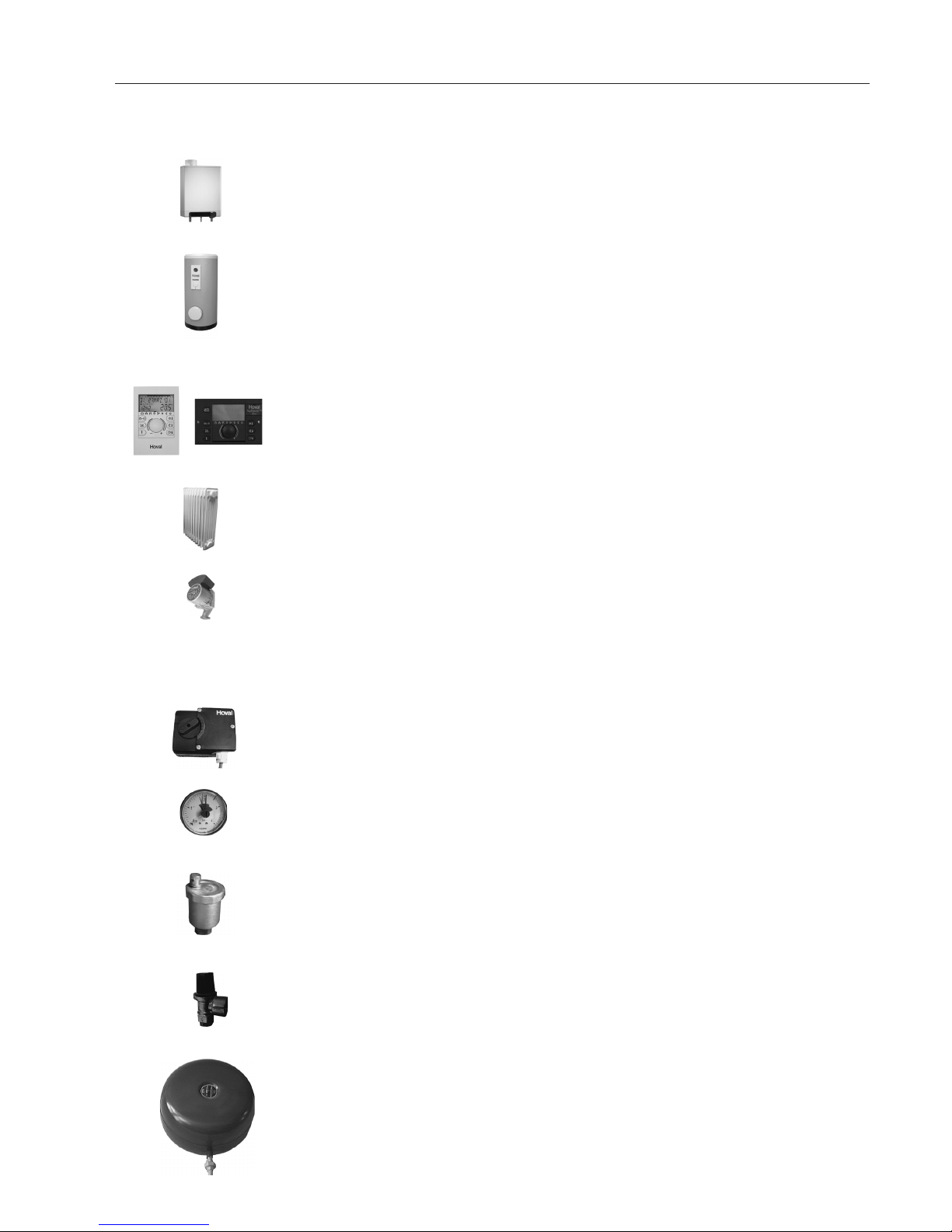
With the Hoval TopGas®you have acquired a product manufactured according to the
stateof-the-art and highest quality standards.
Please ensure that the delivery is consistent with your order and check it is complete.
Also check for possible damage in transit and inform the nearest Customer Service
centre if there is any. For insurance reasons it will not be possible to accept any
subsequent claims.
For the correct installation and operation of your Hoval TopGas®, all applicable laws,
regulations and standards must be complied with; in particular the regulations of the
respective energy supply company. In case of queries, please contact your specialist
installer or the nearest Hoval Customer Service centre.
Assembly or installation of the heating boiler may only be carried out by trained
personnel of an approved installation company. Before starting the boiler for the first
time, an installation inspection and approval of the overall installation by the installer
are required.To guarantee safe and trouble-free operation, operate your Hoval boiler
only according to these operating instructions.
The boiler may only be used for its intended purpose and fuels for which it is suitable
on the basis of its design and for which it has been approved by Hoval.
Do not carry out any changes to the system, otherwise all claims under the guarantee
will be invalidated. Conversion kits are to be installed and the installation approved
by authorised installers or by the Hoval Customer Service.
The reliable and safe functioning of a gas boiler, as well as the achievement of an
optimal effectiveness and clean combustion are only possible and guaranteed if the
system is maintained and cleaned at least once every year.
In the event of a fault or in case of damage, please contact the Hoval Customer
Service to inquire about the necessary repairs. In the meantime, shut down the unit
to avoid any damage.
With the acquisition of a Hoval unit you also obtain a comprehensive guarantee
protection, as indicated in the guarantee conditions of the guarantee pass for your
unit.
This guarantee is, however, dependent on the observance of the operating and instal-
lation instructions and on compliance with the applicable legal regulations. Non-com-
pliance with the above will invalidate all liability and warranty claims against Hoval.
Provided it is used correctly, your Hoval boiler will ensure you enjoy a well heated
home for many years.
The Hoval Customer Service
If you have any doubts in regard to the operation of your Hoval boiler, or minor faults
affect its correct functioning, please contact the nearest Hoval Customer Service
centre.
A telephone call is often enough when it comes to solving small problems. Our trained
Customer Service staff will do everything in their hands to help you.
If a fault can not be solved in this way, a service technician will visit you in order to
solve the problem. We hope you understand that, except in urgent cases, this is not
always immediately possible.
Take advantage of the offer of the Hoval Customer Services for extending the service
life of your Hoval boiler, and ask for a service agreement. Your Customer Services
advisor will be pleased to give you information.
You will find the addresses on the last page..
3. Customer service
i
3. Customer service

7
4 205 534 / 00
4. Functional principle of the heating system
Component Function
Gas heating boiler Burns natural gas safely without harming
the environment. Removes heat from the
exhaust gas generated by combustion
and transfers it to the heating water.
Water heater It holds a reserve of domestic hot water
for consumption (e.g. for showering).
Boiler control Controls and monitors operation of the
heating boiler. Ensures that, whatever the
temperature outside, the room tempera-
ture is as required – in an optimum and
fuelefficient manner.
Radiators, underfloor heating Delivers the heat from the heating water
to the room.
Heating pump Pumps the heating water from the boiler to
the radiators and back to the boiler, where
it is heated up again.
Mixer valve Changes the heater flow temperature
by mixing in colder heater return water
(water that flows to the radiator), so that
the desired room temperature is achieved
regardless of the outside temperature.
Manometer Indicates the water pressure in the heating
system.
Vent Ensures that only heating water and no air
is in the system or heaters.
Safety valve Prevents pressure in the system beco-
ming excessive.
Membrane expansion vessel Keeps the pressure in the system con-
stant.
4. Functional principle of the heating system

8
4 205 534 / 00
5. System start-up
Commissioning of a newly installed system may only be carried out by a qua-
lified installer. A full installation check must be completed prior to start-up.
- Press On/Off to switch the appliance off (LED dark), water pressure is
displayed!
- Open the shut-off valve of the heater flow and return.
- Open the shut-off valve of the gas line that leads to the boiler
- Turn on the main switch outside the boiler room (if available).
Frequently the heating system has an additional safety switch that only
disable the gas burner.
- Before commissioning the TopGas®the stench trap (siphon) in the conden-
sate drain pipe must be filled with water.
5.1 Checks prior to start-up
Check the water level in the heating system.
The heating system must be filled with water and all the air removed.
Observe the regulations regarding antifreeze and water treatment.
Open the shut-off valves in the flow and return lines.
Check the fresh air supply to the heating system.
Check the settings for the operating modes.
5.2 Switching on the system
Open the gas valve.
Turn on the main switch.
Set the boiler control unit to the desired operating mode and temperature.
i
i
4. Functional principle of the heating system / 5. System start-up
Radiator(s) or
underfloor hea-
ting where fitted
Heating boiler
Water heater
Chimney, flue
system

9
4 205 534 / 00
1
0
-
6. Heating system control
On/Off button
(Appliance „Off“ displays water
pressure)
in the edition "classic" without function
Service button (if this button is pressed during normal
operation, the actual value of the current operating
mode of the boiler is displayed in the two-digit display)
Reset button
+ / - (change values)
6. Heating system control
6.1 Operating elements of the boiler control panel / basic control N4.3
Normally the user does not need to change the basic control settings. All necessary settings
have been adjusted by the installer or at the factory.
Operating Status Display in the Service Display
Operating Status
Off, water pressure display
The appliance receives voltage, the heating operation and the DHW mode are switched off, but
the freeze protection is active. The actual water pressure, which does not cause a reaction in any
of the operating modes, is displayed for information only.
Off, no heating requirement
The appliance is ready for operation and will be turned on immediately when there is a heating
or DHW requirement
After-Run Time Pump in Heating or Hot Water Operation
After operating the boiler in the heating or DHW mode, the pump continues to run.
Target Temperature Reached
Should the desired target temperature including the potentially added offset be exceeded, the
burner turns off.
1
0
-
Service display
Operating mode / target value setting / actual value display
During normal operation the operating mode is displayed by the LEDs (DHW / HT)
The following can be adjusted by pressing the temperature selection button:
- Max. Temperature for heating operation (adjustable by using the -/+ button,
the value selected here also limits the target value transmitted via the OT bus)
- Target value for warm water (adjustable by using the -/+ button,
an overlay with the values from the OT bus is possible)

10
4 205 534 / 00
6. Heating system control
2
3
4
5
6
7
Self-Test
The burner regularly checks the connected sensors. During this self-test, the burner does not
execute any other tasks.
Ventilation, Exhaust Ventilation
During the ventilation and the exhaust phase, the number „3“ is shown in the display.
Ignition
During the ignition process the number „4“ is shown in the display. If there is an aborted start, then
a new start will be attempted according to the diagram in item 1.h. A total of 4 start attempts are
permitted before the unit registers a malfunction.
Operating Mode Heat
During the heating operation the target temperature is shown in the two-digit display. If the „service“
button is pressed during the heating operation, the actual temperature is displayed.
Operating Mode Hot Water
During the DHW operation the display shows the target temperature. If the „service“ button is
pressed during the heating operation, the actual temperature is displayed.
Warm Water Heating Operation in Comfort Mode (only TopGas®combi) or Freeze Protec-
tion
If freeze protection is active or if the heat exchanger is heated to a set temperature for the comfort
mode, then “7” is shown in the display.

11
4 205 534 / 00
6.2 Operating elements of the heating control RS-OT
Key Designation Function
2
Daytime room temperature
Set the daytime room temperature.
3Reduced room
temperature Set the night time room temperature or reduced heating.
4DHW temperature Set the domestic hot water temperature. Manual DHW
reloading.
5
Rotary pushbutton Change the values by turning. Confirm the values by pres-
sing. Function selection by pressing and turning.
6Information key • Show the operating data on the display.
• Return to the basic display without saving the values.
7Heating curve set-up Set the heating characteristics
8
Operating mode selection key
Select the operating modes
Holiday Turn off the heating system during the holidays
(frost protection)
Absence Temporarily switch off heating
Party Extended heating
Automatic Automatic heating according to the preset heating times
= normal heating
Summer only DHW; heating off
Constant heating
Constant heating mode
Reduced heating
Constant reduced heating mode
Standby System switched off - frost protection activated
9
6. Heating system control
2
3
4
8
7
5
6

12
4 205 534 / 00
Key Designation Function
2Daytime room temperature Set the daytime room temperature.
3Reduced room
temperature Set the night time room temperature (reduced heating).
4DHW temperature Set the domestic hot water temperature. Manual DHW
reloading.
5
Rotary pushbutton Change the values by turning. Confirm the values by
pressing. Function selection by pressing and turning.
6Information key • Show the operating data on the display.
• Return to the basic display without saving the values.
7Heating curve set-up Set the heating characteristics
Key Designation Function
9Display The basic display shows the day of the week, date
and time of the day, as well as the room temperature.
Possible readouts:
1 Active heating time 24h
2 Weekday display
3 Display of the active operating mode and the clock
programme
4 Time of the day
5 Selected operating mode
6 Date / Day / Month / Year
7 Boiler temperature and room temperature
2
1
3
4
6
7
5
6. Heating system control
6.3 Operating elements of the heating control TopTronic®T/N
5 411
9
678
10
3 2
(in the wall enclosure)

13
4 205 534 / 00
Key Designation Function
8
Operating mode selection key
Select the operating modes
Holiday Turn off the heating system during the holidays
(frost protection)
Absence Temporarily switch off heating
Party Extended heating
Automatic Automatic heating according to the preset heating
times = normal heating
Summer only DHW; heating off
Constant heating
Constant heating mode
Reduced heating
Constant reduced heating mode
Standby System switched off - frost protection activated
9Manual mode /
emission measurement For heating technician only.
10 Display The basic display shows the day of the week, date
and time of the day, as well as the current boiler tem-
perature and room temperature (room station)
Possible readouts:
1 Active heating time 24h
2 Weekday display
3 Display of the active operating mode and the clock
programme
4 Time of the day
5 Selected operating mode
6 Date / Day / Month / Year
7 Boiler temperature and room temperature
11 Brief operating instructions
on the hinged cover
Special brief operating instructions are provided with
the heating control.
2
1
3
4
6
7
5
6. Heating system control

14
4 205 534 / 00
Fault Inspect / Cause Fix See page
Gas boiler - Is power available - Check fuses.
does not start - Check the power plug
- Press On/Off button
(LED lights up)
- Is the gas valve open - Open it
- Is the service display blinking - Press the reset button
- Contact customer service
- Is there too little gas - Open gas valve
(service display shows - Contact gas provider
blinking 4 or 5)
Radiators - Are the valves of the heater flow - Open the flow and return valves
do not and return open
get warm
- Is the On/Off button in the Off - Switch unit on 9
position (LEDs are dark) - Press On/Off button
(LED lights up)
- Is the timer clock of the TopTronic®T - Check according to the
set correctly operating manual for the heater control
- Check water level and water pressure - Top off the heat. system and bleed off air 15
- Are the radiator valve open - Open the valves
- The heater circ. pump is not running - Open the latch screw
- Turn the shaft end hard with a screwdriver
until the resistance goes away
- Mixing valve does not open automatically - Open valve man.; Contact customer service
No warm - The load pump is not running - Unscrew the latch screw
water - Turn the shaft end hard with a screwdriver
until the resistance goes away
- Is air in the load pipe - Bleed air manually
- Manually activate the automatic bleeder
7. Check list in case of faults
Please note! In case of faults in operation,
please carry out checks in accor-
dance with the above checklist.
If you are unable to correct
the fault, please call either the
installation engineer or the
Hoval Customer Services.
i
7. Check list in case of faults

15
4 205 534 / 00
If the water pressure in the system is too low – readable on the manometer (installed externally)
or in the two-digit display when the boiler is “Off” (LED is dark) - contact your installation
professional or top off water.
Topping off the heating system
To fill up or top off your heating system you can use regular drinking water. In some
exceptional cases the water quality may not be suitable for use in a heating system
(highly corrosive or calcium rich water). If that is the case, please contact a reputable
specialist.
Instructions
• Press the On/Off button to turn the appliance off (LED is dark); the water
pressure is displayed.
• The heater flow and return valves must be open.
• The boiler fill and drain faucet is accessible on the underside of the boiler.
• Connection between the fill faucet and the water faucet is made by using a
hose:
- Fill the hose with water before connecting it to the boiler to prevent air from
getting into the heating system.
- Remove the hose after filling the system to ensure a safe disconnect.
• Fill the water in slowly while checking the water level at the hydrometer or at the
display.
• After topping off the water, briefly open the bleeder valves until all the air has
escaped from the system.
8. Checking the water level

16
4 205 534 / 00
9. This is how you can save energy!
Room temperatures and
operating times of the hea-
ting system have a decisive
influence on the fuel con-
sumption.
1°C reduction in the room tem-
perature setting leads to an
economy in fuel consumption
of up to 6%. Therefore, please
take note of the following tips:
• Avoid setting room temperatures
above 20°C and adjust your he-
ating system accordingly.
• It is worth turning off the radia-
tors in unused rooms, provided
there is no risk of frost and no
damage caused by moisture
either to the building fabric or its
furnishings is to be expected.
• In the main living rooms, there is
frequently heat gain due to body
warmth, televisions, fireplaces
and also sunshine.These cannot
be compensated by a weather-
dependent regulatory system. It
may be worth installing a remote
control (RS 30) or a room sensor
or fitting thermostats to the radi-
ators in these rooms.
When it is draughty in the
house, it is not merely un-
pleasant; it indicates at the
same time
that heating energy is being
wasted.
You therefore save fuel if you...
• keep windows and doors closed
in winter..
• close chimney dampers when
the fire is out.
• only operate kitchen and ba-
throom fans when it is necessary
to remove moisture and odours.
• only ventilate briefly, but fre-
quently.
• seal doors and windows, to pre-
vent continuous leakage loss.
Insulation helps to keep in
valuable warmth.
Take advantage of all these pos-
sibilities and...
• close window and door shutters
at night.
• make sure that heating pipes
and hot water pipes in unheated
rooms are properly insulated.
As low a radiator temperature
as possible will prevent unne-
cessary heat losses.
For this reason, the radiator
must always be enabled to give
its heat up to the
room without hindrance. You
should therefore avoid:
• radiator coverings.
• window-sills which obstruct heat
flow because the outlets are co-
vered.
Heating the hot water too
offers opportunities for sa-
ving.
• The hot water temperature
should be set as low as possible.
Experiment to find out the lowest
temperature at which there is still
enough hot water available.
• If your system includes a hot wa-
ter circulating pump, it is worth
shutting this down at night by
means of a time-switch.
ENERGY
9. This is how you can save energy!

17
4 205 534 / 00
10. Hoval Service / sales program
There are many advantages in
favour of having a service ag-
reement
• Your heating system will always
be optimally adjusted – this saves
heating costs and helps preserve
the environment.
• A high level of operational reliabili-
ty, as in the course of servicing ear-
ly warning of possible faults may
be recognised and corrected.
• Optimum settings of your system
and the regular maintenance will
together guarantee a longer ser-
vice life for your system.
You will find we have product
ranges which offer you possi-
bilities in all sizes of new buil-
ds and renovated buildings.
Heat generation systems
Compact heating centres for oil
firing, heating boilers for oil- and
wood-firing, burners, solar energy
production systems (collectors) and
heat-pumps for making use of geo-
thermal heat or heat generated by
wind and water.
Heat distribution systems
and buildings services
Water heaters (boilers), radiators,
heating walls, convectors, low-tem-
perature radiators, heating and ven-
tilation regulators, circulation pumps
and heating oil tanks of both plastic
and concrete.
Heat recovery and industrial
ventilation systems
• The advantageous all-in price..
The Hoval specialists are well-
equipped and will give you
good and reliable service.
When you give us an order, please
call the regional Service Controller,
who works in close co-operation
with the service engineers in the
area. The service call can then be
made without delay.
Modern Hoval system engi-
neering with a guaranteed fu-
ture includes:
10. Hoval Service / sales program

Hoval LTD
Northgate
Newark
Nottinghamshire NG24 1JN
Phone: +44 1636 67 27 11
Fax: +44 1636 67 35 32
www.hoval.co.uk
Hoval France SAS
335 Avenue de Colmar
F-67100 Strasbourg
Téléphone +33 3 88 60 39 52
Téléfax +33 3 88 60 53 24
www.hoval.fr
Hoval Gesellschaft mbH
Hovalstrasse 11
A-4614 Marchtrenk
Telefon +43 7243 550-0
Telefax +43 7243 550-15
www.hoval.at
Hoval Italia S.r.l.
Via per Azzano San Paolo, 26/28
I-24050 Grassobbio (BG)
Telefono +39 035 52 50 69
Telefax +39 035 52 58 58
www.hoval.it
Germany
Switzerland
Austria
Italy
France
Hoval (Deutschland) GmbH
Karl-Hammerschmidt Strasse 45
D-85609 Aschheim-Dornach
Telefon +49 89 92 20 97-0
Telefax +49 89 92 20 97-77
www.hoval.de
Hoval Herzog AG
General-Wille-Strasse 201
CH-8706 Feldmeilen
Telefon +41 44 925 61 11
Telefax +41 44 923 11 39
www.hoval.ch
United Kingdom
Responsibility for energy and the environment
This manual suits for next models
2
Table of contents
Other Hoval Water Heater manuals
Popular Water Heater manuals by other brands

clage
clage Zip CEX9-U Instructions for the user

Bradford White
Bradford White Combi2 TTW C-DW2-TW50T10FBN Specification sheet

Haier
Haier FCD-JTHA50-III user manual

Takagi
Takagi T-H3M-OS Installation manual and owner's guide

Viadrus
Viadrus Space Energy 200V Installation and operation manual

ThermoFlow
ThermoFlow Hydrex user manual

AEG
AEG BMU 60 Operation and installation instructions

clage
clage DBX 18 BASITRONIC Operating instructions for the user

clage
clage 27921 installation instructions

flowair
flowair LEO FS S Technical documentation operation manual

Noritz
Noritz GQ-C2857WS US owner's guide

Thermor
Thermor VM75 instruction manual