howen Hero ME40-02V3 User manual

1
Hero ME40-02V3 Dash Camera
User Manual

2
Content
1. Features.................................................................................................................................................................3
2. Dimension and Definition....................................................................................................................................3
3. Quick start for using.............................................................................................................................................4
3.1 Mobile APP Connect................................................................................................................................. 4
3.2 Set up MDVR via APP.............................................................................................................................. 5
3.3 Record Setting........................................................................................................................................... 6
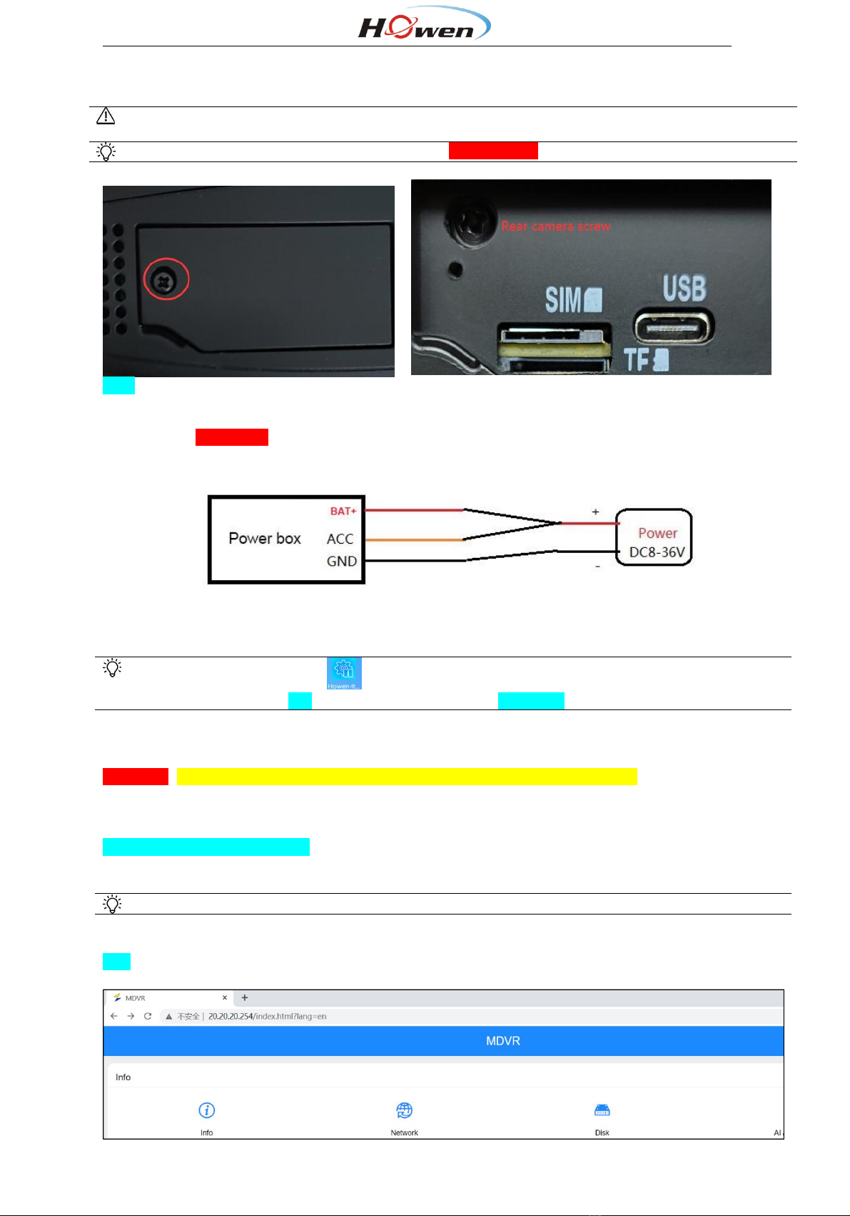
3.3.1 General and Main-stream............................................................................................................. 6
3.3.2 Sub-stream...................................................................................................................................... 7
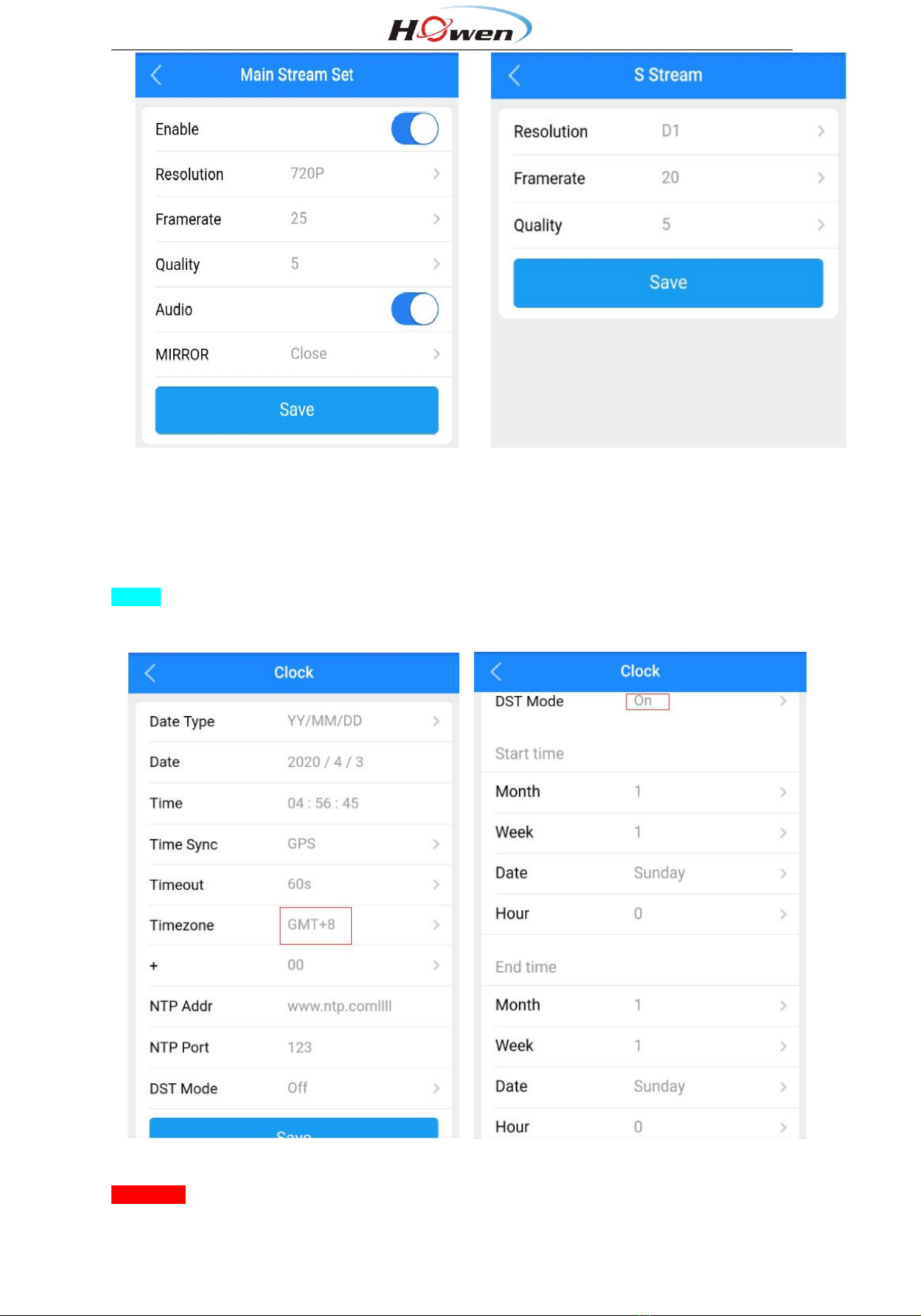
3.4 Time zone setting.......................................................................................................................................7
3.5 Connect to Platform.................................................................................................................................. 8
3.5.1 Device ID setting............................................................................................................................ 8
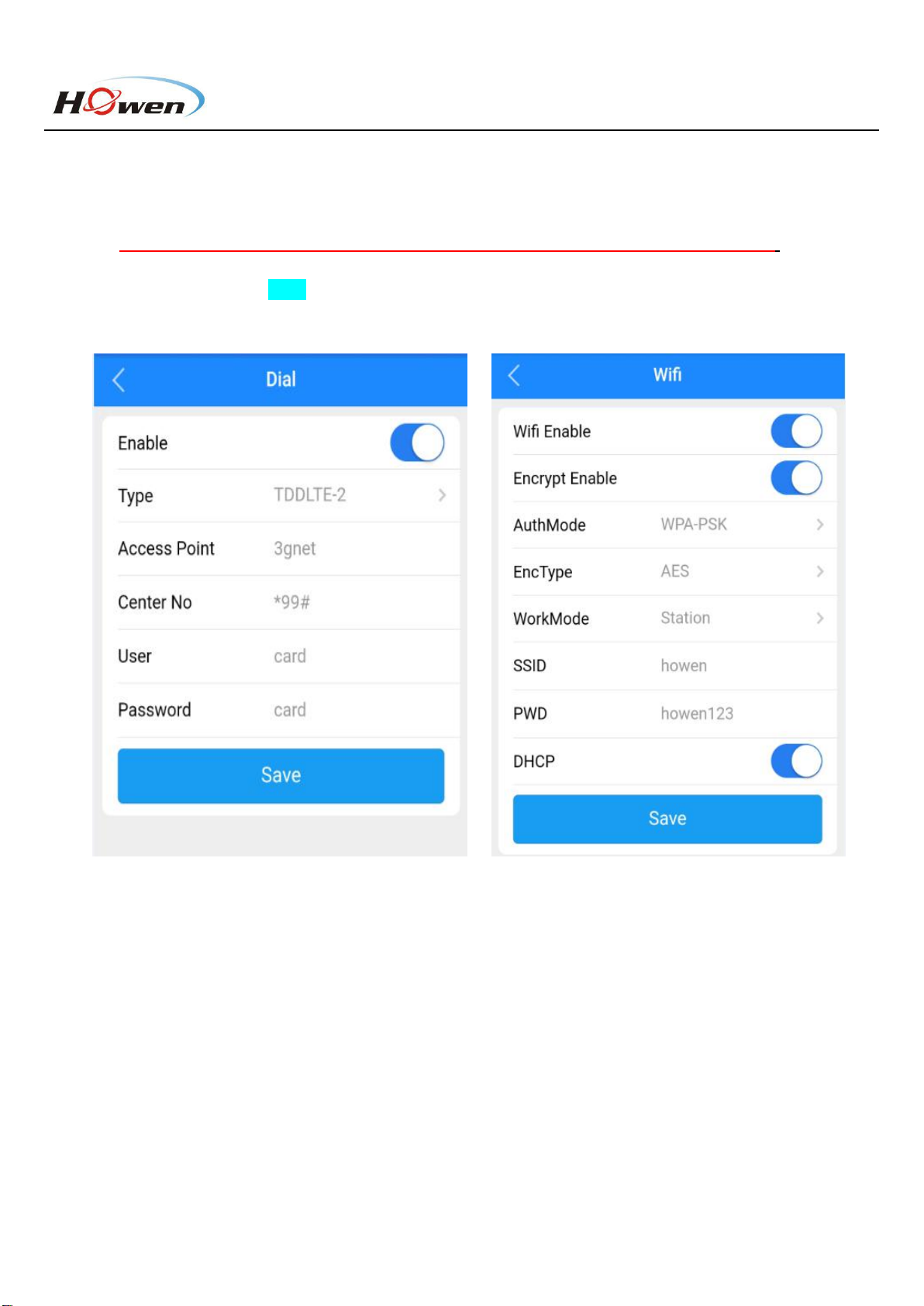
3.5.3 Dial setting.....................................................................................................................................10
3.5.4 Wi-Fi setting.................................................................................................................................. 10
3.5.5 Add device onto VSS................................................................................................................... 11
3.5.6 Network Status............................................................................................................................. 11
3.6 Info page................................................................................................................................................... 13
3.6.1 Info.................................................................................................................................................. 13
3.6.2 Disk.................................................................................................................................................14
3.6.3 AI Authorization.............................................................................................................................15
4. Installation........................................................................................................................................................... 15
5. Calibration........................................................................................................................................................... 20
5.1 DMS........................................................................................................................................................... 20
5.2 ADAS Calibration..................................................................................................................................... 21
5.3 Face Recognition.....................................................................................................................................24
5.3.1 Add Driver In VSS........................................................................................................................ 24
5.3.2 Driver issue................................................................................................................................... 25
6. Main Menu.......................................................................................................................................................... 26
6.1 Search....................................................................................................................................................... 26
6.2 System.......................................................................................................................................................27
6.2.1 Terminal..........................................................................................................................................27
6.2.2 User................................................................................................................................................ 28
6.2.3 Clock...............................................................................................................................................29
6.2.4 Power............................................................................................................................................. 30
6.2.5 Sleep Configuration..................................................................................................................... 31
6.2.6 Disk.................................................................................................................................................32
6.2.7 Audio...............................................................................................................................................33
6.2.8 Serial.............................................................................................................................................. 33
6.2.9 Parameter...................................................................................................................................... 34
6.3 Video.......................................................................................................................................................... 34
6.3.1 General.......................................................................................................................................... 35
6.3.2 Main-stream.................................................................................................................................. 35
6.3.3 Sub-stream....................................................................................................................................36
6.3.4 Storage...........................................................................................................................................36
6.4 Alarm..........................................................................................................................................................37
6.4.1 I/O................................................................................................................................................... 38
6.4.2 External alarm...............................................................................................................................39
6.4.3 Speed............................................................................................................................................. 39
6.4.4 G-sensor........................................................................................................................................ 40
6.4.5 Voltage........................................................................................................................................... 42
6.4.5 DMS................................................................................................................................................42
6.4.6 ADAS.............................................................................................................................................. 43
6.4.7 Face Setting.................................................................................................................................. 44
6.4.8 Other...............................................................................................................................................45

3
1. Features
✓All-in-one design, built-in GPS, LTE, Wi-Fi, easy to install and maintain
✓Brand-new design and optimized heat-sink
✓Wide angle FHD video recording and streaming
✓Easy configuration via mobile App
✓Extendable for additional third camera
✓Support AI features (optional): DMS, ADAS
✓Built-in microphone and speaker for two-way communication
✓Cost-effective and reliable
2. Dimension and Definition
POWER: Power LED.
NET: Network status indicator, it stays on while linking.
GPS: GPS signal status, it stays on when it’s valid.
ALARM: Alarm indicator while device triggering alert.
External Cable definition
It can connect 3rd channel camera, SOS button, RS232 device, Input and output.
Power box cable definition

4
3. Quick start for using
Install Memory card and SIM card
The TF card (a.k.a. Micro SD card) is automatically formatted when it is inserted into the device at
the first time.
Recommended storage capacity 32GB-256GB, MLC material [Important!], Class 10 or above.
Unscrew the cover at the bottom of device. Insert the SIM card and TF cards, please mind the direction.
Tips: USB port is for connecting USB drive via OTG cable.
In-Office test: DC12V, 5A or higher current power source is recommended.
Connect the power box to the device first. Connect the red & orange wire together to positive and the
black wire to GND.
Fig.3.1 Office test
3.1 Mobile APP Connect
Download Howen-iTool from Google Play (iOS version available soon).
The Wi-Fi name is APxxxxxx and the password is 12345678
Step1: Power on the dash camera.
Step2: Enter the Wi-Fi settings on your mobile phone, search this Wi-Fi.
Step3: Connect the dash camera to this Wi-Fi, input the password.
Attention: Device will be at AP mode for 2 minutes then switch to Station mode. During this 2 minutes,
if it connects via Howen-itool, it will stay at AP mode.
Search Dash camera via APP
Step1: Connect dash camera to Wi-Fi of your mobile phone.
Step2: Open the mobile APP, the APP will search the device automatically.
If auto search not started, please follow step 3.
Step3: Click the refresh button on the right upper of the screen, it will start searching. (Fig.3.2).
Tips: You can also use PC to access this AP and configure via web at office.

5
Fig.3.2 Search Fig.3.3 Login
3.2 Set up MDVR via APP
Step 1: Click the settings button at the bottom, enter MDVR configuration homepage.
Step 2: Input the password and login. (Fig.3.3)
Step 3: Then you will get the homepage. (Fig.3.4)
Default password is 111111. You can change it.

6
Fig.3.4 Home page
3.3 Record Setting
3.3.1 General and Main-stream
Step 1: Enter the General page, select H.265 or H.264 (Some platforms do not support H.265), if
there is no real-time preview, please confirm the TV system: PAL or NTSC (Fig.3.5)
Step 2: Select Video →Main stream. (Fig.3.6)
Step 3: Confirm CH (refers to video Channel) setting. Higher resolution, higher video quality (1
refers to the top quality) and better frame rates will consume more storage space.
Step 4: Click on Save. (Fig.3.7)
Fig.3.5 General Fig.3.6 Main stream

7
Fig.3.7 Channel setting Fig.3.8 Sub stream
3.3.2 Sub-stream
The sub-stream is used for live streaming.
Video would be clearer with higher resolution, better frame rates and quality, but also consumes more
cellular data. (Fig.3.8)
Notice:Quality,1 is the best, to save cellular data consumption, 5 or 6 is recommended.
3.4 Time zone setting
Fig.3.9 Time Fig.3.10 DST (Daylight Saving Time)
Timezone:Please set according to your preferred time zone, default is GMT + 08. (Fig.3.9)
DST mode: Daylight Saving Time, set according to your local rule. (Fig.3.10)

8
Set the Month, Week, Days, specific hour, then set the offset time (according to your local regulation,
normally it’s 60 minutes.
3.5 Connect to Platform
3.5.1 Device ID setting
Step1: MDVR configuration.
Step2: Click Terminal Configuration.
Step3: Set a unique device ID for it, it will be used for adding device onto the platform (Fig.3.11)
In addition, recommended to set the plate number which matching that of the vehicle in which
the dash camera will be installed.
Fig.3.11 Device ID
3.5.2 Network setting
Network Setup page: Center settings, IP setting, Dial settings and Wi-Fi settings.
The device will access the VSS (Howen platform) server or 3rd party platform via 4G/Wi-Fi.

9
Step 1: Settings → Network.
Step 2: Click Center Settings.
Step 3: Select server 1 or server 2, H-protocol.
Step 4: Select the H-protocol, input the server IP address and port. (Fig.3.11)
Server IP: It’s your server PC’s IP address which already deployed the platform.
Port: 33000. It’s set to point to VSS platform.
Server 1&2 both could support either VSS or 3rd party platform via H-protocol, such as Wialon, Navixy etc.
Fig.3.12 Center setting
More function
FTP server: You can build your own FTP server, and upload video to it.
Timed snapshot: Take snapshots according to the set interval and upload snapshots to VSS.
Fig.3.13 FTP server Fig.3.14 Timed snapshot

10
3.5.3 Dial setting
Enable: On.
Type: WCDMA / EVDO / TDDLTE / FDDLTE-1 / FDDLTE-2 for option.
Access Point: Input Access Point name.
Notice:Each telecom operator has various APNs , please consult your telecom operator first.
Center No: Default setting is *99# In most cases, you don’t need to change it.
User&Password: Set up SIM card service user name and password. Please inquire your SIM card carrier first!
(Fig.3.15)
Fig.3.15 Dial setting Fig.3.16 WI-FI setting
3.5.4 Wi-Fi setting
You can use Wi-Fi to access internet. To set up, simply follow your router’s configuration.
Wi-Fi Enabled: Turn it On.
Encrypt Enable: On / Off.
Auth Mode: Open / Shared / WPA / WPA-PSK, set according to your router configuration.
EncType: NONE /WEP/ TKIP / AES, set according to your router configuration.
Work Mode: Station only.
DHCP: Turn it on/off, default is On.

11
3.5.5 Add device onto VSS
Login to the VSS platform via Web or VSS client. (Fig.3.17 )
Device No. Input device ID.
Device Name: Input Plate number.
Device Type: Select the device model.
Fleet: Need to create a fleet first. Then select this device.
Audio-video Number: Channel numbers, set according to the video channel needed.
Input/Output: Input according to device type.
Click to show more info about device, then save it.
Fig.3.17 Add device for VSS
3.5.6 Network Status
Go to system info menu, check the network info. (Fig.3.18)
If dial failed, please double-check the 3.5.3 Dial setting.
If it shows disconnect, please check all the steps one by one.

12
Fig.3.18 Network Status

13
3.6 Info page
In addition to the network status info, there are other important information.
3.6.1 Info
Check Info page, where you get general information about the device, e.g. MCU and firmware version, device ID and
plate number, GPS info etc. (Fig.3.19 & 3.20)
Fig.3.19 INFO
The important information as following:
MCU version: MCU software version
FW Version: The current device firmware version.
System Voltage: The current device operational voltage.
Dev. ID.: Device ID.
SIM Version & IMEI: 4G module information.
I/O status: Check the I/O electrical level status.1is high, 0(lower than 3V) is low. You can check once the device
connected with an I/O device, such as panic button.
G-sensor: It shows the G-sensor value. Move the device and check if those value change.

14
Location Status:
It will show the longitude and latitude, satellites number. You can check more details for Satellites. (Fig.3.21)
The signal intensity should be more than 30dB, satellite Number more than 4 satellites.
Fig.3.20 INFO Fig.3.21 Satellites signal
3.6.2 Disk
Shows storage info. (Fig.3.22)
Fig.3.22 Disk Fig.3.23 AI Authorization

15
3.6.3 AI Authorization
ChipId: The Chip-set ID is for activating the DMS/ADAS function.
DMS/ADAS Authorization Information: Activation status.
4. Installation
Step1: Install Memory card and SIM card for device.
Step2: Stick the bracket
Tips: Before paste the bracket, please measure and mark the center of vehicle’s windshield at first.
Wipe clean windshield (make sure there is no oil/dust) and dry it. Tear off the 3M sticker, paste one side on holder. If
the temperature was below 20 degrees, to use a hot-air cylinder to dry at 50 degrees for 5-10 seconds is
recommended, then paste on.
Step3: Fix the device gently
Take out the screws and Dashcam.
Then insert the screw lock, keep it adjustable till installation is finalized on vehicle.
Installation Attention:
Horizontally: the device shall be installed around the center of windshield.
Vertically: adjust the device to get the best positioning for the front camera first, especially if ADAS function is
required.

16
Step3: Wiring connection
Take out the power adaptor/box, connect to device first. Connect the red wire (power positive +) to BAT+ of vehicle,
and orange wire (ACC) to ignition of vehicle, and the black wire (power negative -) to BAT- on the vehicle battery.
Do check that all wires correctly connected, and make sure to wrap connection joints with electric tape when
connection is finalized.
OBD method
If already purchased OBD cable from our side, connect the wires to power box, BAT+ to VCC, GND to GND, ACC to
ACC.
For the OBD port, connect to your vehicle’s OBD interface.

17
Step4: Adjust the ADAS camera
If ADAS is activated, need go to ADAS calibration view, make a roughly adjustment firstly.
Regarding how to calibrate ADAS accurately, please refer to Part 5.2.
Tips:
Connect your mobile phone to Wi-Fi shared by the device, open the APP to get the real-time preview, and make
sure the calibration angle is right (Refer to the below picture, the horizon line should be lined up with the ground
level 15-20m away).
Notice:
Step5: Adjust the rear camera

18
Use the screw-driver to adjust the view angle, till the images appear suitable.
After calibrating/adjusting the cameras, tighten up the screw to fix the device.
Step6: Wiring
Connect the I/O, DMS camera, RS232 external device.
1. I/O connection
To bring out the best of ADAS’s Lane Departure Warning (LDW) feature, need to connect I/O cable to turning signal
lights of the vehicle.
Pick Sensor-IN1 and Sensor-IN2 of serial cable, connect the L-turn and R-turn signal light of the vehicle respectively
(Must be consistent with the actual connection wire and then set R/L-turn item).
For wait time, recommend to set as 0 or 1 second.

19
2. Install the DMS camera
If you purchased optional DMS features, connect the DMS camera provided by your supplier to extension cable and
set it to CH3. Install the DMS camera 60-120cm away in front of the driver, make sure nothing laid between lens and
driver. Angle is adjustable (left/right, up/down) to make sure DMS camera could capture driver’s face entirely.
Attention: Currently not support fixing DMS cam on A-pillar of the vehicle
Standard DMS camera position as shown below:

20
If the steer wheel blocked the view of DMS camera, try the following 2 options (also refer to the pics below):
1. Install a holder to lift the DMS camera higher.
2. Move the DMS camera aside for 15-20cm or less than 15 degrees (towards vertical central line of the driver face),
but shall not across the vertical central line of the windshield. Then adjust the camera, make sure it faces the driver,
and driver face shall appear in the central field of camera view.
5. Calibration
5.1 DMS
If your device supports DMS function, connect the DMS camera to the extension cable and select CH3.
1. After you install the camera, sit in front of the DMS camera, and face the camera lens.
2. Go to DMS set menu, Click Calibration
Table of contents
Other howen Dashcam manuals