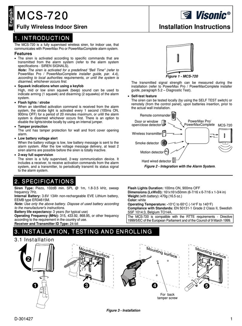
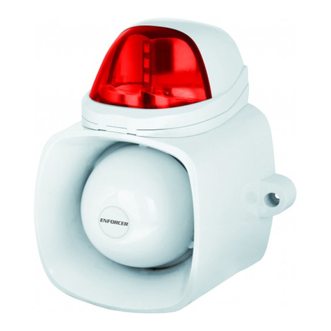
HOWLER Freelink FL Series User manual

HOWLER FREELINK SITE ALARM
USER MANUAL
Models: FLCP and all Howlers alarms with a /FL suffix
DO NOT DISCARD –ESSENTIAL
INFORMATION IS CONTAINED IN THIS
MANUAL
Issue 8
9/10/2013

2 |H O W L E R F r e e l i n k TM U s e r M a n u a l I s s u e 8
Introduction
WELCOME
Firstly, a message of thanks from us all at Howler, for choosing the FreelinkTM battery
operated radio link site alarm. Over the years Howler has become synonymous with tough,
reliable products designed for rigorous environments, and we hope that this product will
fulfil your every expectation.
We would issue one word of warning, however, and that is to remind you that radio waves
are not magic! Unlike cables, you cannot see them, and so it is more difficult to guarantee a
connection at all times. You will find that the system disconnects at times, particularly if the
building layout changes, and you may need to reposition the Howler alarms to regain a
connection. Remember that radio waves will never pass through solid metal, so a Howler
situated in a metal container, without any window will never work.
You can be assured that the Freelink system is equipped with comprehensive continuous
fault monitoring, so if disconnections occur it will let you know.
We wish you every success with your installation. If you have problems, the Trouble
Shooting section of this manual will help in most cases, but if problems persist, contact your
supplier.
Howler technical helpline: 01202 536800
SAFETY NOTE
The Howler alarms emit a very loud sound when in the alarm state, and the user should
avoid prolonged exposure to the sound within a 1m range, without hearing protection.
LOG BOOK
A Log Book is provided with the system in which all checks, and events should be recorded,
including false alarms, faults etc. It is a condition of the warranty that this book is used. A
clear record of all events is an immense help in diagnosing problems, and can be used to
support any warranty claims.
Installer contact details:

3 |H O W L E R F r e e l i n k TM U s e r M a n u a l I s s u e 8
Contents
CONTENTS
TERMINOLOGY
4
OPERATING INSTRUCTIONS IN BRIEF
5
1
INSTALLATION
6 - 12
1.1
Planning and Panel Set-up
7 - 8
1.2
Howler alarm set-up
9 - 11
1.3
Howler address table
10
1.4
Forcing a connection between Howlers
12
1.5
Channels
13
2
BASIC OPERATION
14
3
MAINTENANCE
15 - 16
3.1
Regular checks
15
3.2
Battery replacement
15
3.3
Silent battery test
16
3.4
Control panel power down
16
4
WARNINGS & DISCONNECTS
17-19
4.1
Short and long disconnects
17
4.2
Low battery warnings
18
4.3
‘System 18’
18
4.4
‘Watchdog’
18
4.5
Panel power down
19
5
SET-UP MODE
20 - 21
5.1
Connect Stations
20
5.2
Setting the power level
20
5.3
Setting the disconnect seconds
20
5.4
Setting the automatic battery test interval
21
5.5
Setting the Sync threshold
21
5.6
Changing the User code
21
5.7
Changing The Set-up code
21
5.8
Changing the siren time-out duration
21
5.9
Two stage alarm
22
6
DETECTION
23
7
TROUBLE SHOOTING
24 - 30
DECLARATION OF CONFORMITY
31

4 |H O W L E R F r e e l i n k TM U s e r M a n u a l I s s u e 8
Terminology
Terminology
To assist understanding of the terminology with this manual the following illustrations
indicate the parts referred to.
Control Panel Howler alarm (or Howler) LCD (Liquid Crystal Display) DIL Switch
Default Codes
The factory default panel codes are as follows:
User Code: 1234
Set-up Code: 2468
To re set the default codes at any times, simply power down the panel, by disconnecting the
batteries. Hold the switch on the back of the panel PCB down whilst re-connecting the
batteries and the default codes will be restored (see below)
‘Restore defaults’button
Hold button whilst powering up

5 |H O W L E R F r e e l i n k TM U s e r M a n u a l I s s u e 8
SOUND
ALARMS
Enter USER
CODE Press 2
SILENCE
ALARMS
Enter USER
CODE Press 4
RESET
PANEL
Enter USER
CODE Press 1
SILENCE
FAULT SIGNAL
Enter USER
CODE Press 3
TEST MODE Enter USER
CODE Press 6
Instructions in brief
OPERATING INSTRUCTIONS IN BRIEF
This section outlines the operation of the system in brief, and can be used to train staff who need to
be able to deal with the day-to-day occurrences.
To illuminate the LCD display, simply press any button.
When entering the USER CODE, press the buttons slowly and firmly, waiting for a * to appear on
the top row of the LCD for each number pressed.
To SOUND all alarms, enter the USER CODE followed by ‘2’ – ‘Evacuate’. To silence alarms press
‘CLEAR’.
To SILENCE alarms, enter the USER CODE followed by ‘4’ – ‘Mute Sirens’. Locate the Howler which
has been activated, reset it, return to the panel and reset the panel (see
below).
To RESET the panel after an event, enter the USER CODE followed by ‘1’ – ‘Reset alarms’. The panel
will return to normal display.
Faults and disconnects
If any Howler becomes temporarily disconnected, the panel will emit an intermittent beep, and the
number of the Howler which has become disconnected will be displayed on the LCD, with the legend
‘short disconnect’. No immediate action needs to be taken at this stage, but the situation should be
monitored. If the Howler does not reconnect within a preset time, the panel will emit a constant
beep, and the number of the Howler which has become disconnected will be displayed on the LCD,
with the legend ‘long disconnect’. The disconnected Howler should be located and it should be
repositioned. Return to the main panel, and, if necessary, reset the panel (see above).
The fault beep can be silenced by entering the USER CODE followed by ‘3’ – ‘Mute Panel’
Test Mode
To facilitate weekly tests of all Howlers, the system will automatically reset whilst in the TEST MODE,
without the need to return to the panel after testing each Howler.
To set the TEST MODE, enter the USER CODE, and press ‘6’ – ‘Test Mode’. Once the test has been
completed, enter the USER CODE again and press ‘1’ – ‘Reset’.

6 |H O W L E R F r e e l i n k TM U s e r M a n u a l I s s u e 8
Installation
1. INSTALLATION
1.1 Planning
Prior to installation it is important to plan the locations of the Howler alarms and the
Control Panel. The Control Panel should be housed in a secure, weatherproof location
within a reasonable distance of the first Howler alarm. Radio waves travel a lot further in
open air, where they can travel is straight lines, so the panel can often be sited in a cabin
remote from the main building. However, it is sensible to avoid situating the panel in such a
position where a lot of large vehicle movement occurs between the panel and the first
Howler alarm. In such a situation, disconnects may occur quite frequently, unless the signal
is particularly strong.
The Howler alarms themselves should be sited on exit routes in easily accessible places,
which are unlikely to be obstructed. In most buildings, the Howlers will need to be no more
than 30 –50m apart, depending on the number of obstructions between them. The
stairwells are ideal locations. This ensures that Howlers are in easy reach of personnel and
that the sound levels are adequate to warn all persons present. Wherever possible Howlers
should be mounted on mobile fire points or backboards so that they can be repositioned
easily and quickly. The Howler alarms should be securely mounted to prevent damage by
dropping or falling, and as high as is reasonably practicable.
If the system has 16 or more Howlers a little more thought is required in planning the
locations of the Howlers. Only Howlers addressed 02 –17 have the ability to act as
repeaters, passing the messages on to other Howlers. Howlers addressed 18 and above will
only send and receive messages from another Howler (or direct to the panel), they will not
pass the messages on to others.
Whilst it is difficult to predict with any accuracy the route that radio waves will take, as a
general rule, the lower address numbers work best near the Control Panel, with the higher
numbers being located at the end of the line, further away from the Panel.
Do not install Howlers in close proximity to other radio devices.

7 |H O W L E R F r e e l i n k TM U s e r M a n u a l I s s u e 8
1.2 Panel Set-up
1) Access to the Control Panel fixing points is gained by removing the two cover plates,
one at the top of the panel and one at the bottom. These are removed by pushing
the small lever on the left hand side of the plate, and pulling towards you (see
below).
2) Remove the four Pozi screws and the panel front can then be lifted off carefully.
3) Install the 4 x D cell batteries in the battery holder. Ensure that the key switch on
the side of the panel is turned in the anti-clockwise direction otherwise the power
will be switched off. The LCD display on the panel will illuminate as soon as the
batteries are installed. The screen will read:
The LCD has a power saving facility which means that it will switch off after
approximately 30 seconds if no other buttons are pushed. To illuminate the LCD,
simply press any button.
4) Replace the panel front, taking care to ensure that it is correctly located, and replace
the 4 Pozi screws.
5) Attach the panel securely to the wall in your desired location, using appropriate wall
fixings. There are a number of places on the panel backplate available for screw
fixings. Finally push the two cover plates back into position at the top and bottom of
the panel. The panel is now ready for connecting to the Howlers.
Installation
Alarms normal
No alarms

8 |H O W L E R F r e e l i n k TM U s e r M a n u a l I s s u e 8
1.2.1 Connecting Howlers to the panel
(NB If you have purchased a Quick-Start kit, the panel will already have the correct Howler
addresses connected. This can be checked, by following the procedure described in this
section)
1) Enter Set-up Code > Press 1 (Connect Stations)
2) A list of addresses is shown from 02 to 52. The status of each station is shown as
AUTO, OFF or F <No>. Any Howler which you need to be connected should be AUTO.
(See below)
3) Use the arrow keys to scroll down and up the addresses. To change the status of any
address, simply push ENTER when the arrow is displayed against that desired
address number.
4) Once you have ensured that all the addresses required are switched to AUTO, and all
the addresses not required are switched OFF, the Howler alarms can be set up.
NB As soon as this process is completed, the Control Panel will be trying to make
connection with the Howler alarms. The Panel may well issue some disconnection
warnings whilst the Howlers are being installed, so be prepared to silence the fault
warning if necessary (see section 2.2).
Installation

9 |H O W L E R F r e e l i n k TM U s e r M a n u a l I s s u e 8
1.3 Howler Alarm Set-up
If you have purchased a Quick-Start kit, the Howler alarms will come pre-addressed. The
address number is displayed on the outside of the Howler. In this instance the section on
addressing the Howler (points 2 and 3) is not relevant.
1) Open the Howler by removing the screw at the bottom of the Howler, using the
security allen key provided.
2) Each Howler must have a unique address, or number. This is simply set by means of
the DIL switch on the PCB within the Howler. The table following illustrates the
positions for the DIL switch for each address.
This photograph shows the DIL switch set up for address 02, and this is how it is graphically
represented on the table which follows:
(NB The addresses shown are for Channel 1 Howlers –see section 1.5 for information
regarding changing the Channel, if required)
Installation
Address:
02

10 |H O W L E R F r e e l i n k TM U s e r M a n u a l I s s u e 8
Howler Address Table
The white squares indicate the switch positions. (please note that these configurations are
for channel 1)
Installation
Address:
02
Address:
03
Address:
04
Address:
05
Address:
06
Address:
07
Address:
08
Address:
09
Address:
10
Address:
11
Address:
12
Address:
13
Address:
14
Address:
15
Address:
16
Address:
17
Address:
18
Address:
19
Address:
20
Address:
21
Address:
22
Address:
23
Address:
24
Address:
25
Address:
26
Address:
27
Address:
28
Address:
29
Address:
30
Address:
31

11 |H O W L E R F r e e l i n k TM U s e r M a n u a l I s s u e 8
3) Once the addresses have been set, the Howlers can be mounted in their final
locations, using appropriate fixings.
4) The Howlers can now be powered up one by one, starting with the Howler nearest
the Control Panel. Connect both sets of batteries by pushing the battery connectors
into place. Secure the cable ties around the ‘D’ cell batteries.
5) The LED lights on the PCB will illuminate briefly as soon as the power is connected.
Once the Howler has made connection with the panel or nearest Howler, both LEDs
will flash continuously. The Howler cover can then be replaced, and the security
screw refastened.
6) Work your way through the Howlers, ensuring that each Howler makes connection
(i.e the LEDs are flashing)
7) Sometimes Howlers will not make connection, and they may need re-positioning to
obtain a connection. A Howler can be encouraged to make connection with another
Howler, by bringing them close together. Once connection is made, they can be
moved apart again and the connection will usually be maintained.
8) The strength of each connection is shown on the Control Panel, so you can see any
‘weak’ connections. Enter the Set-up Code > Press 1 (Connect stations). The signal
strength is shown as a minus number, with 0 being the strongest connection. See
Figure 4. You can see from this information, therefore, if there are any weak
connections that may need improving by repositioning of a Howler.
Fig.4
Channel number
Signal strength
Number of seconds since the Howler
communicated with the panel
Number of the station to which the
Howler is connected
Installation

12 |H O W L E R F r e e l i n k TM U s e r M a n u a l I s s u e 8
NB The system will take time to settle down and find the strongest signal routes.
During this time disconnects may well occur. It is advisable to allow at least 30 minutes
before leaving the system. If disconnects do occur, resetting the panel will often help
speed up the re-connection time (User Code > Press 1 ).
It is advisable to run a silent battery test as soon as the system is connected up, as
follows: User Code > Press 5 (Battery test) (See section 3.3)
The user should expect some short disconnects during the first 24 hours whilst the
system settles down and finds the best routes.
1.4 Forcing a connection between Howlers
Sometimes following set-up, certain Howlers will either fail to make connection with
another Howler, or will make a weak connection and therefore ‘Short disconnect’ warnings
will be issued frequently. The Howler may be attempting to connect using a route which
does not offer the strongest signal.
If there is a Howler in the vicinity which logically ought to be able to offer a connection (and
it is addressed 02 - 17), the Howler can be forced to attempt connection to that one Howler.
The method to achieve this is as follows.
Enter the Set-up Code > Press 1 (Connect stations). Scroll to the address number with the
weak connection, using the up and down arrows. Having reached the required address press
the ENTER key and the panel display will change from AUTO to F <No.> (See below). Now
select the number of the Howler to which you want to make connection using the 1 and 2
buttons. Pressing ‘1’ will increase the address number, and pressing ‘2’ will decrease the
address number. Once you have entered the correct address, press CLEAR to exit the
Connect Stations section.
You may need to take the panel near to the Howler you are trying to force connection on, to
ensure that the Howler receives the forcing instruction. Once the Howler is happily
connecting up, the panel can be returned to its correct location.
In this example, station 04 has been set to connect
with station 03
Installation

13 |H O W L E R F r e e l i n k TM U s e r M a n u a l I s s u e 8
1.5 Channels
There are 4 different channels on which the Howler Freelink system can operate. This
means that up to 4 systems can be run in close proximity without interfering with each
other. The factory set Channel is 01, and this is displayed in the Connect Stations section on
the panel by the address 01 (see below).
There should be no need to change the Channel, unless there is a neighbouring Howler
Freelink system.
To change Channels on the panel, enter the Set-up Code > Press 1 (Connect Stations).
Ensure the curser is against address 01 (using the arrow up and down keys), and Press the
required Channel number (e.g. 1, 2, 3 or 4). The panel will prompt you to confirm the
change by pressing ‘5’.
The panel may bleep and display ’01 Watchdog’. Simply reset the panel as follows: User
Code > Press 1 (Reset).
The Channel then has to be changed on each of the Howlers. This is achieved by changing
the settings on the DIL switches on the PCB within each Howler. The last two switches on
the DIL switch (numbers 7 and 8) set the Channel. The settings for each channel are shown
below. In each case the setting shown is for Howler address 2, only the Channel has
changed.
Installation
Channel: 01
Address: 02
Channel: 02
Address: 02
Channel: 03
Address: 02
Channel: 04
Address: 02

14 |H O W L E R F r e e l i n k TM U s e r M a n u a l I s s u e 8
2. BASIC OPERATION
2.1 Alarms
In the event of fire, the alarm is raised by operating the switch on any Howler alarm. All
alarms will the sound, and the premises should be evacuated. The panel will display an
indication of which Howler alarm has been operated, and the responsible person should
check whether the alarm is real.
To silence the alarms: User code > Press 4 (Silence alarms). The panel will emit a fault
signal. (The factory set User code is 1234)
To reset the system: Before resetting the system, the switch on the Howler alarm which has
been operated needs to be reset. Method of operation and resetting of the Howler will
depend on the model. For models: HO1/FL, HO2/FL, HO3/FL, HO4/FL: Push the switch to
sound alarm. Reset using switch or key as appropriate to the model. For model: HOCP/FL:
Push the callpoint plastic section firmly on the black circle. A small fluorescent strip will
appear in the top left hand corner of the aperture and the alarm will sound. Reset by
inserting the black plastic ‘key’ into the circular hole in the base of the callpoint. Push the
‘key’ firmly upwards until the callpoint resets and fluorescent strip is hidden.
Once the Howler has been reset, return to the panel and enter: User Code > Press 1 (Reset
alarms)
The system offers a ‘two stage alarm’ facility – see section 5.9
2.2 Warning indications
If any fault or other abnormal condition occurs on the system, the panel will emit a fault
signal, either intermittent or continuous. The LCD display will indicate the nature of the
warning. If the nature of the warning is not urgent, the user may choose to silence the
signal as follows: User Code > Press 3 (Silence fault buzzer).
Silencing the warning signal does not switch the system off, and if any Howler is operated,
the alarms will still sound.
NB Warnings should not be ignored –the user should make every effort to resolve the
problem as soon as possible. The level of urgency will depend on the nature of the
warning.
See section 4 on Faults & Disconnects for further information.
Occasionally the panel may issue a spurious low battery warning, particularly in cold
weather. This can always be checked by running a silent battery test and then immediately
resetting the panel (see section 3.3).
Basic Operation

15 |H O W L E R F r e e l i n k TM U s e r M a n u a l I s s u e 8
Maintenance
3. MAINTENANCE
3.1 Regular checks - IMPORTANT
The following checks should be carried out by the user to ensure that the system remains in
good working order:
1) Daily: check the panel by simply pressing any button. The screen should illuminate
and display the message ‘No alarms’.
2) Weekly: At least one Howler alarm point should be tested each week, on a rotating
cycle, so that all alarm points are tested from time to time. To carry out the test
enter: User Code > Press 6 (Test Mode).
Test the selected Howler alarm by operating the switch. Only the Howler tested will
sound, and the panel will automatically silence the alarm after approximately 10
seconds and reset the panel. Any number of Howler alarms can be tested whilst in
this mode, and the panel will automatically reset each time.
NB When the test is complete the panel must be reset: User Code > Press 1 (Reset
alarms).
3) Six monthly: All the Howler alarms should be tested as per 2)
All checks as well as faults and disconnects should be noted in the log book provided to
show evidence of regular checks. This is a condition of the warranty.
3.2 Battery replacement
The Howler alarms have two power sources, both being standard dry cell batteries which
are readily available. The siren is powered by a PP9 battery, and the radio link function is
powered by 2 x D size batteries.
The panel will give warning when any battery requires replacement. The fault signal will
sound intermittently and the panel will display a message indicating which battery is low.
When the battery is completely drained, the Howler will disconnect. The panel refers to the
PP9 battery as ‘9V battery’ and the D size batteries as ‘3V battery’.
It is always advisable to run a silent battery test prior to changing batteries, to check the
result. A silent battery test is run by pressing: User Code > Press 5 (Battery test). The list of
Howlers will be displayed. Scroll to the Howler you wish to test using the arrow up and
down keys, then press ENTER. The panel will display ‘Batt test pending’. If there is a genuine
problem with the battery, the warning will be given again.

16 |H O W L E R F r e e l i n k TM U s e r M a n u a l I s s u e 8
To replace the batteries, simply locate the Howler alarm indicated by the panel; remove the
cover; remove the old batteries and replace with new. It is advisable to secure the batteries
with a cable tie. Wait until the red LEDs on the PCB are flashing consistently (indicating that
the station is connected), before replacing the cover. Return to the panel and reset the
system: User Code > Press 1 (Reset alarms).
Whilst the panel is displaying a ‘Battery Low’ warning, the fault signal can be silenced by
entering: User Code > Press 3 (Silence Fault Signal).
It is recommended that batteries are replaced with good quality, long life batteries for the
maximum reliability of the system. Standard rechargeable batteries can also be used, but
typically they will not last as long as non-rechargeable batteries.
Waste batteries should be recycled.
3.3 Silent battery test
The batteries are automatically tested every time the alarms are sounded. If you wish to
conduct a silent test of the batteries at any time press: User Code > Press 5 (Battery test).
Then select either ‘All’, ‘Panel’, or a particular station number by using the up and down
arrows. Press Enter and the test will be carried out. The panel will display the legend ‘Batt
test pending’ until the test is complete. Once the test is complete the panel will return to
‘No alarms’ unless a fault is found with the batteries.
3.4 Control Panel Power-Down
If you need to switch off the whole system (e.g. at night when the system is not required),
simply insert the key into the switch on the side of the panel and turn in a clockwise
direction. To switch back on, turn the key in the anti-clockwise direction. NB Keys should
never be left in the panel, in case unauthorised persons switch off the system.
Turn Clockwise to switch ‘off’ Turn Anti-Clockwise to switch ‘on’
Maintenance

17 |H O W L E R F r e e l i n k TM U s e r M a n u a l I s s u e 8
Warnings and Disconnects
4. WARNINGS AND DISCONNECTS
4.1 Short and Long Disconnects
If any Howler becomes disconnected for more than 120 seconds (2 minutes), the Control
Panel will display the address of the disconnected Howler followed by the words ‘Short
disconnect’. This gives you an early warning, and if there has been some change to the site
layout, or position of the Howler, this indication will alert you that you may have to
reposition the Howler to regain connection. E.g.:
The system will attempt to regain connection with the disconnected Howler, and if it
succeeds, the message will disappear. If, however, it fails to regain connection after 700
seconds (11.6 minutes), the Control Panel will emit an intermittent beep. Pressing any key
on the Panel will illuminate the LCD, and the address of the disconnected Howler will be
shown followed by the words ‘Long disconnect’. E.g.:
The warning signal can be silenced as follows: User Code > Press 3 (Mute panel), but be
aware that the Howler will need reconnecting as soon as possible. Try to re-establish
connection by repositioning the Howler and resetting the system: User Code > Press 1
(Reset alarms).
Check whether the Howler has re-connected at the Control Panel as follows: Set-up Code >
Press 1 (Connect stations). The signal strength is shown as a minus number, with 0 being
the strongest connection.
Alarms normal
02 Short disconnect
Alarms normal
02 Long disconnect

18 |H O W L E R F r e e l i n k TM U s e r M a n u a l I s s u e 8
Warnings and Disconnects
4.2 Low Battery Warnings
Each Howler has two power sources, both being standard dry cell batteries which are readily
available. The siren is powered by a PP9 battery, and the radio link function is powered by 2
x D size batteries.
The Control Panel will give warning when any battery requires replacement. An intermittent
fault signal will sound and the panel will display a message indicating which battery, in
which Howler requires replacement. E.g.:
The Control Panel refers to the PP9 battery as the ‘9V battery’ and the D cell batteries as the
‘3V battery’
4.3 ‘System 18’
If any Howler alarm is operated, and then reset within 10 seconds, the Panel will
automatically silence all Howlers and the panel will display the warning ‘System 18’. This can
be cleared by resetting the panel - User Code > Press 1 (Reset alarms). This function is
designed to reduce the impact of any deliberate nuisance alarms and any other type of false
alarm.
4.4 ‘Watchdog’
Sometimes the control panel will display the legend: ‘01 Watchdog’. Usually resetting the
panel will clear this (i.e. User Code > Press 1 (reset)). If this doesn’t work, simply power
down the panel by turning the key switch on the side of the panel. Leave for 30 seconds
than switch back on again. The panel should display ‘No alarms’ once again.
Turn Clockwise to switch ‘off’ Turn Anti-Clockwise to switch ‘on’
It will take the panel approximately 5 minutes before it has reconnected all stations and is
ready to operate normally again.
Alarms normal
02 Low battery 3V

19 |H O W L E R F r e e l i n k TM U s e r M a n u a l I s s u e 8
4.5 Panel Power Down
If the panel appears to ‘freeze’, and you cannot enter the User menu, simply power down
the panel by turning the key switch on the side of the panel. Leave for 30 seconds then
switch back on again.
It will take the panel approximately 5 minutes before it has reconnected all stations and is
ready to operate normally again.
Warnings and Disconnects

20 |H O W L E R F r e e l i n k TM U s e r M a n u a l I s s u e 8
Set-up Mode
5. SET-UP MODE
This mode is entered by pressing the Set-up code. (The default Set-up code is 2468). There
are various functions within this mode which are designed to assist installation and
maintenance.
5.1 Connect stations
Enter Set-up Code > Press 1 (Connect Stations)
This function lists the connected stations and the signal strengths. To connect or disconnect
a station simply scroll up and down the list using the arrow keys, and when the desired
station is reached toggle between AUTO, F <No.> and OFF using the ENTER key.
The two digits immediately after the AUTO/F <No.>/OFF column tells you which station that
Howler is connected to (station 01 is the control panel).
The third column after the AUTO/F <No.>/OFF column shows the signal strength, with 0
being the strongest possible signal.
The final column of figures displays the number of seconds since the panel last made
contact with that station. This number updates every time any key is pressed.
5.2 Battery test interval
Enter Set-up Code > Press 2 (Batt test interval)
This function displays the number of days at which the batteries will be tested, if, for any
reason, the alarms are not tested as per the maintenance instructions. This can be changed
if required by using the arrow up and down keys, and pressing Enter when the desired
number is reached.
The factory setting is 0 days. Additionally, the batteries are automatically tested every time
the alarms are sounded.
5.3 Setting the power level
Enter Set-up Code > Press 3 (Set power level)
This function displays the power level at which signals are transmitted. The power level
ranges from 10 dBm to -30dBm. The factory set level is 5dBm. If it is proving difficult to
connect stations, the power level can be increased, but be aware that the batteries will
drain quicker the higher the power level.
To change the power level use the arrow up and down keys, then press enter when the
desired power level is reached.
This manual suits for next models
1
Table of contents
Other HOWLER Security System manuals

