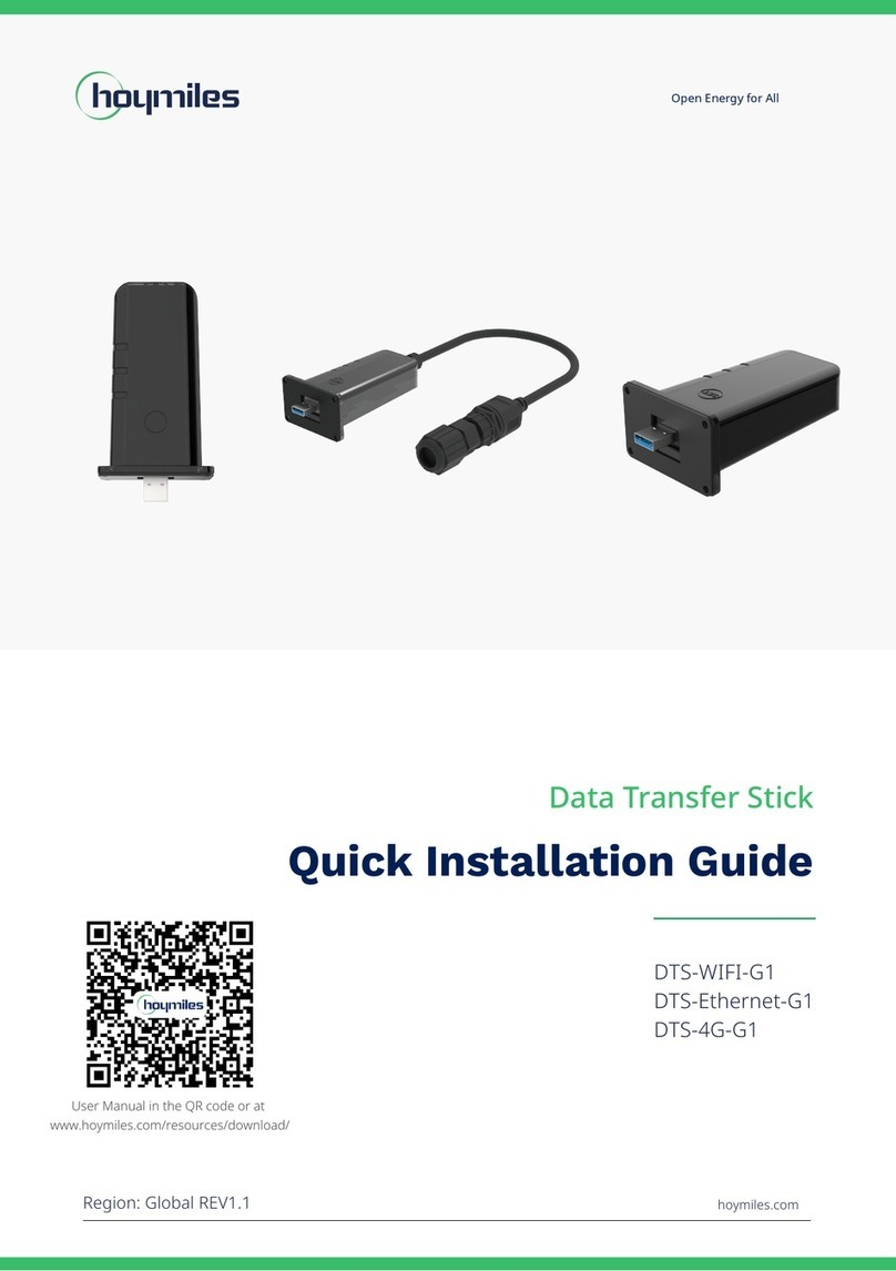
Hoymiles DTU-Pro-S User manual

Open Energy for All
Data Transfer Unit
USER MANUAL
DTU-Pro-S
Region: Global V202111 hoymiles.com

© 2021 Hoymiles Power Electronics Inc. All rights reserved. 01
Data Transfer Unit User Manual
CONTENTS
1. Important Safety Information 02
1.1 Read This First 02
1.2 Safety Instructions 02
1.3 User 02
1.4 Support and Contact Information 02
1.5 Other Information 02
2. Hoymiles Microinverter System 03
2.1 Microinverter 03
2.2 DTU 03
2.3 S-Miles Cloud 03
3. Interface Layout 03
3.1 For Wi-Fi Version 03
3.2 For 4G Version 04
4. Additional Features 05
4.1 Export Management Function (RS485 port) 05
4.2 DRM Port (for Australia and New Zealand only) 05
5. Installation Planning and Preparation 06
5.1 Pre-installation 06
5.2 Dimensions 06
5.3 System Installation Steps 07
6. DTU Installation 08
6.1 Installation Instructions 08
6.2 Online Setting 08
6.3 Complete Installation Map 12
7. Micro Toolkit 13
7.1 Connect to the DTU 13
7.2 Field Commissioning and Data Viewing 14
8. Site Creation on S-Miles Cloud 20
8.1 Site Creation 20
8.2 Customer Login 26
8.3 Browse Station on Webpage 27
8.4 View Phone App 27
9. DTU Replacement 28
10. LED Indicators 29
11. Technical Data 30

© 2021 Hoymiles Power Electronics Inc. All rights reserved. 02
Data Transfer Unit User Manual
1. Important Safety Information
1.1 Read This First
This manual includes important instructions for installing and maintaining the Hoymiles Data Transfer Unit
(DTU-Pro-S).
DTU-Pro-S is only compatible with Hoymiles new HMS and HMT series of microinverters.
1.2 Safety Instructions
Symbol Usage
This indicates a hazardous situation that can result in deadly electric shocks,
serious physical injuries, and fire incidents.
This indicates that directions must be strictly followed to avoid safety hazards
such as equipment damage and personal injury.
This indicates that the act is forbidden. You should stop, use caution and fully
understand the operations explained before proceeding.
• Note that only professionals can install or replace DTU.
• Do not try to repair DTU without Hoymiles’ permission. If the DTU is damaged, please send it back to
your installer for repair/replacement. Disassembling DTU without Hoymiles’ permission will invalidate
the remaining warranty period.
• Please read all the instructions and warnings in the technical specications carefully.
• Do not use Hoymiles products in a way that is not suggested by the manufacturer. Otherwise it can
cause death, personal injuries, or equipment damage.
1.3 User
This manual is only for professional installation and maintenance personnel.
1.4 Support and Contact Information
If you have technical queries concerning our products, please contact your installer or distributor. If further
technical support is required, please contact our support team at service@hoymiles.com.
For other questions please contact info@hoymiles.com
1.5 Other Information
Product information is subject to change without notice. The user manual will be updated regularly. Please
refer to Hoymiles official website at www.hoymiles.com for the latest version.

© 2021 Hoymiles Power Electronics Inc. All rights reserved. 03
Data Transfer Unit User Manual
2. Hoymiles Microinverter System
The complete Hoymiles PV microinverter system is composed of PV microinverter, Hoymiles gateway DTU
and Hoymiles monitoring system S-Miles Cloud.
The microinverter converts direct current to alternating current and sends each module’s power generation
and operation data to the DTU.
DTU can communicate with multiple microinverters, collect their operation data, and send them to S-Miles
Cloud.
On S-Miles Cloud, you can check the real-time data of each PV module and perform remote operation and
maintenance.
2.1 Microinverter
Microinverters convert the DC output of PV modules into grid-compliant AC power. They send their
operation data and the output information of PV modules to the DTU, which is the hardware basis of
the module-level monitoring. With conversion efficiency up to 96.7% and MPPT efficiency up to 99.9%,
Hoymiles microinverters rank among the first class in the industry worldwide.
2.2 DTU
DTU is the key component in Hoymiles microinverter system. It works as the communication gateway
between the Hoymiles microinverters and S-Miles Cloud. The DTU communicates with the microinverter in
a wireless way and collects the operation data of the system. Meanwhile, the DTU connects to the Internet
using different communication options such as Ethernet, Wi-Fi or 4G and communicates with S-Miles Cloud.
The operation data of the microinverter system will be uploaded to S-Miles Cloud via DTU.
2.3 S-Miles Cloud
It collects the operation data and status of the microinverters in the system and provides module-level
monitoring for the users and maintenance staff. The following diagram shows the Hoymiles Microinverter
system.

© 2021 Hoymiles Power Electronics Inc. All rights reserved. 04
Data Transfer Unit User Manual
3. Interface Layout
3.1 For Wi-Fi Version
BC DE
A
Item Description
ASD Card Slot
BDTU Power Indicator
C DTU Communication Indicator (with server)
DDTU Communication Indicator (with microinverter)
E DTU Alarm Indicator
FWi-Fi Antenna
GRS485
H DRM Port (for Australia / New Zealand only)
IEthernet Port
JUSB Port
KReset Bottom
LPower Port
MSub-1G Antenna
3.2 For 4G Version
C
AB
DEF
Item Description
A SIM Card Slot
BSD Card Slot
CDTU Power Indicator
D DTU Communication Indicator (with server)
EDTU Communication Indicator (with microinverter)
F DTU Alarm Indicator
G4G Antenna
HRS485
I DRM Port (For Australia / New Zealand only)
JEthernet Port
KUSB Port
LReset Bottom
MPower Port
NSub-1G Antenna

© 2021 Hoymiles Power Electronics Inc. All rights reserved. 05
Data Transfer Unit User Manual
4. Additional Features
4.1 Export Management Function (RS485 port)
The Hoymiles Smart Power Export Management can intelligently control the output power of the PV
system, and maximize your power generation without violating grid export regulations. At the same time,
this system can also accurately display the power and production of the PV system with the measuring
meter, so that users can trade the PV production online based on the data on S-Miles Cloud.
In Hoymiles Export Management solution, Hoymiles gateway DTU-Pro-S and additional meter (CT optional)
are necessary. In the case of export limitation, the meter can be installed at the load side or the grid side.
As shown below, the gateway DTU will dynamically adjust the PV power production according to the export
power or load consumption as measured by the meter, so that the export power does not exceed the preset
limit. To display the PV production in an accurate way, the meter needs to be installed at the output of the
PV system.
Load Consumption
Power Production
Potential PV Power
5 kW Export Limitation0 kW Export Limitation
kW kW 35
30
25
20
15
10
5
0
4:00 6:00 12:00 16:00 20:00
35
30
25
20
15
10
5
0
4:00 6:00 12:00 16:00 20:00
Note: Please refer to Hoymiles technical note “Power Export Management System” for more details.
4.2 DRM Port (for Australia and New Zealand only)
DRM port is provided to support several demand response modes as shown below by connecting external
control device with a standard RJ-45 connector. DTU-Pro-S supports DRM0/5/6/7/8 if used with Hoymiles
microinverters.
Mode Requirement
DRM0 Operate the disconnection device
DRM1 Do not consume power
DRM2 Do not consume at more than 50% of rated power
DRM3 Do not consume at more than 75% of rated power AND Source reactive power if
capable
DRM4 Increase power consumption
(subject to constraints from other active DRMs)
DRM5 Do not generate power
DRM6 Do not generate at more than 50% of rated power
DRM7 Do not generate at more than 75% of rated power AND Sink reactive power if
capable
DRM8 Increase power generation
(subject to constraints from other active DRMs)

© 2021 Hoymiles Power Electronics Inc. All rights reserved. 06
Data Transfer Unit User Manual
5. Installation Planning and Preparation
5.1 Pre-installation
5.1.1 System Capacity
The DTU-Pro-S is capable of monitoring up to 99 PV modules. If the communication between the DTU
and microinverter is affected by the installation conditions, the number of PV modules that the DTU
can monitor may be reduced.
Note: The maximum number of modules is only possible in open space when installation conditions
detailed in DTU and microinverter manuals are fulfilled and the microinverter and DTU are properly
placed apart as required.
5.1.2 Environmental Requirements for DTU Installation:
• The DTU should be installed away from dust, liquid, acidic, or corrosive gas.
• The ambient temperature should be between -20ºC and 55ºC.
If you plan to install the DTU on the wall, please prepare two #8 (4.166 mm diameter) screws and a
screwdriver in advance.
5.2 Dimensions

© 2021 Hoymiles Power Electronics Inc. All rights reserved. 07
Data Transfer Unit User Manual
5.3 System Installation Steps
Work that needs to be done on site Work that can be done either on site or at home. Step 6
must be done correctly in order to complete these steps on
site.
1. Install the PV modules and
microinverters
2. Locate the DTU 8. Site creation
9. Add microinverter ID
10. View data on S-Miles
Cloud
3. Connect the microinverter
to the grid
4. Power on DTU
5. Connect DTU with Internet
7. Mount the DTU on the wall
(optional)
6.Use Micro Toolkit for onsite
inspection (optional). Check
the communication between
microinverters and DTU

© 2021 Hoymiles Power Electronics Inc. All rights reserved. 08
Data Transfer Unit User Manual
6. DTU Installation
6.1 Installation Instructions
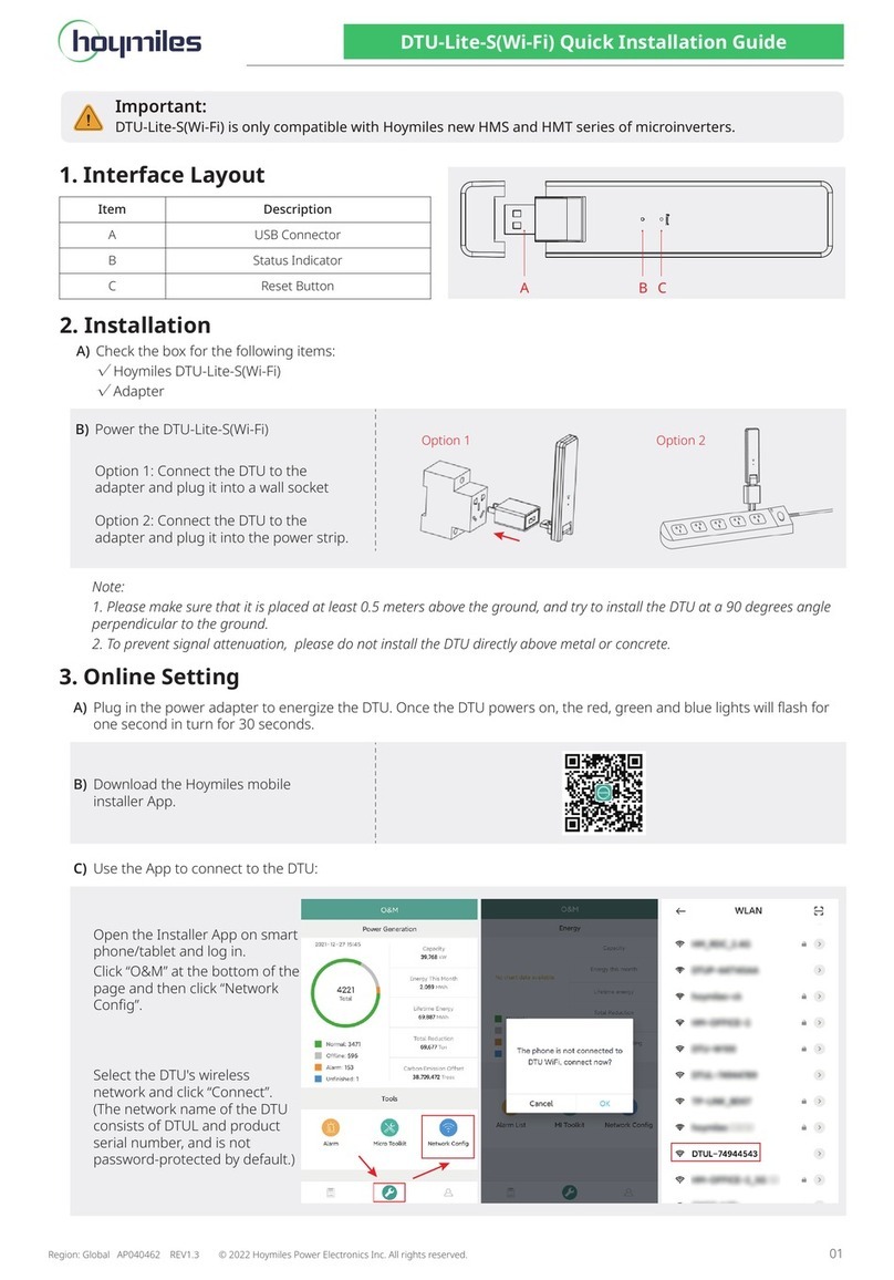
A) Check the box for the following items:
9Hoymiles DTU-Pro-S (Two Antennas)
9Adapter
9Bracket
95 Pin Plug
B) Take DTU-Pro-S out from the box, check and tighten the antenna
C) Choose an installation location.
Installation principles:
9Install the DTU on the top oor to increase the signal strength.
9Install the DTU near the center of the PV array.
9Install the DTU at least 0.5 m above the ground and more than 0.8 m away from the corner.
Note: To prevent signal attenuation, please do not install the DTU above metal or concrete.
D) Choose the installation method
Option 1: Mount the DTU on the wall
9Mount the bracket on the wall. Please choose at
least two screw holes (one from each side) to x
the bracket (the M4 screws need to prepare by the
installer).
9Fix DTU-Pro-S to the bracket’s upper buckle.
9Fix DTU-Pro-S to the bracket’s lower buckle gently
until you hear a click. Please make sure that the
antennas are vertical to the wall.
Option 2: Place the DTU on table. Please make sure the antennas are vertical to the table.
6.2 Online Setting
A) Plug in the adapter to power on the DTU.
B) Download the Hoymiles Installer app.

© 2021 Hoymiles Power Electronics Inc. All rights reserved. 09
Data Transfer Unit User Manual
C) Choose the way DTU-Pro-S connects to the Internet, and prepare the following items if needed.
9For Wi-Fi: The network name and key of the Wi-Fi
9For 4G version: 4G SIM card and APN
9For Ethernet: Ethernet cable
D) Set up the DTU connection on mobile phone.
9Open the Installer app on smart phone/tablet and log in.
• Click “O&M” on the bottom of the page and then “Network Cong”.
9Select the DTU’s wireless network and click “Connect”. (The network name of the DTU consists of
DTUP and product serial number. In the following example, the DTU ID is 65200316 and the network
name is DTUP-65200316.)

© 2021 Hoymiles Power Electronics Inc. All rights reserved. 10
Data Transfer Unit User Manual
E) Set up the Internet
9For Ethernet
Connect the router to the DTU Ethernet port with a Lan cable.
Go back to “Network Config” interface and select “Ethernet”.
Click “Send to DTU” and a popup box will appear. Confirm and exit.
9For Wi-Fi
Go back to “Network Config” interface. Select “Wi-Fi” and complete the Wi-Fi configuration.
Select the available Wi-Fi and enter the password.

© 2021 Hoymiles Power Electronics Inc. All rights reserved. 11
Data Transfer Unit User Manual
Click “Send to DTU” and a popup box will appear. Confirm and exit.
9For 4G
Insert the SIM Card into the SIM Card slot on the side of DTU until it clicks.

© 2021 Hoymiles Power Electronics Inc. All rights reserved. 12
Data Transfer Unit User Manual
Go back to “Network Config” interface and select “4G”.
Please get APN information from your telecom operator and modify APN accordingly.
Click “Send to DTU” and a popup box will appear. Confirm and exit.
Note: Once the command is successfully issued, you will exit the Network Config page and the DTU
will start to connect to the network after 30 seconds.
6.3 Complete Installation Map
Please complete the installation map.
A) Peel the serial number label (as circled below) from the DTU and place it on the installation map.
B) Complete system information of the installation map shown as follows.

© 2021 Hoymiles Power Electronics Inc. All rights reserved. 13
Data Transfer Unit User Manual
7. Micro Toolkit
Micro Toolkit is one of the toolkits that come with the S-Miles Cloud app. It can be used for on-site
inspection after the PV power station is complete, so that the operation of microinverter can be monitored
without Site Creation.
7.1 Connect to the DTU
9Open the Installer app on smart phone/tablet and log in.
9Click “O&M” on the bottom of the page and then “Micro Toolkit”.
9Select the DTU’s wireless network and click “Connect”. (The network name of the DTU consists of
DTUP and product serial number, and is password-free by default.)

© 2021 Hoymiles Power Electronics Inc. All rights reserved. 14
Data Transfer Unit User Manual
7.2 Field Commissioning and Data Viewing
7.2.1 Data Overview
1. Click O&M and enter Micro Toolkit.
2. If you have already created the power station on the monitoring platform, you can directly view
the data and information on the overview page.
7.2.2 Add Microinverter
If power station is not yet created on the platform, you need to type in microinverter SN to view
power station data as instructed below.
1. Click “Power generation” button

© 2021 Hoymiles Power Electronics Inc. All rights reserved. 15
Data Transfer Unit User Manual
2. Press the “Add Device” button to add the microinverter to the list. (The microinverter added here
is only used for on-site debugging, and it will not be uploaded to the server, nor can it replace the
power station creation on S-Miles Cloud.)
3. You can add microinverter via “Automatic Search” or typing in the microinverter ID or scanning the
ID.

© 2021 Hoymiles Power Electronics Inc. All rights reserved. 16
Data Transfer Unit User Manual
4. The search result of microinverters and microinverter added will be displayed in the list. Tap the
button on the right if you want to delete it.
5. Confirm that the microinverter ID in the list is correct, and tap save.

© 2021 Hoymiles Power Electronics Inc. All rights reserved. 17
Data Transfer Unit User Manual
7.2. 3 View Microinverter Data
1. Click “Power Generation”. You can see the list of the microinverter and PV power of each
microinverter.
2. If you want to see more details of one microinverter, just click the serial number, then you can
check the input and output data on the page shown as below.
Note: If the microinverter signal is so weak that the real-time data are not updated, move the DTU
closer to the microinverter.

© 2021 Hoymiles Power Electronics Inc. All rights reserved. 18
Data Transfer Unit User Manual
7.2.4 View Communication Status with Microinverter
1. Re-enter Micro Toolkit and tap “Connection Status”.
2. On this page, you can check the signal strength between the DTU and each microinverter. Tap the
signal icon to enter the respective microinverter page (signal quality is constantly refreshing).

© 2021 Hoymiles Power Electronics Inc. All rights reserved. 19
Data Transfer Unit User Manual
3. You can also Tap the button to switch the signal quality and real-time data page.
Note: If the microinverter has no signal, please check whether the microinverter is powered on or
refer to the microinverter user manual for troubleshooting.
Table of contents
Other Hoymiles Network Hardware manuals
Popular Network Hardware manuals by other brands

Tandberg Data
Tandberg Data RDX QuikStation 4 Quick start guides

FieldServer
FieldServer FS-8700-22 X30 Driver manual

Patton electronics
Patton electronics ForeFront 2616RC user manual

Meridian
Meridian Meridian 1 Option 11C Mini installation guide

Cypress Semiconductor
Cypress Semiconductor LUPA user guide

Edge10
Edge10 EDGESTORE NAS400 Specifications