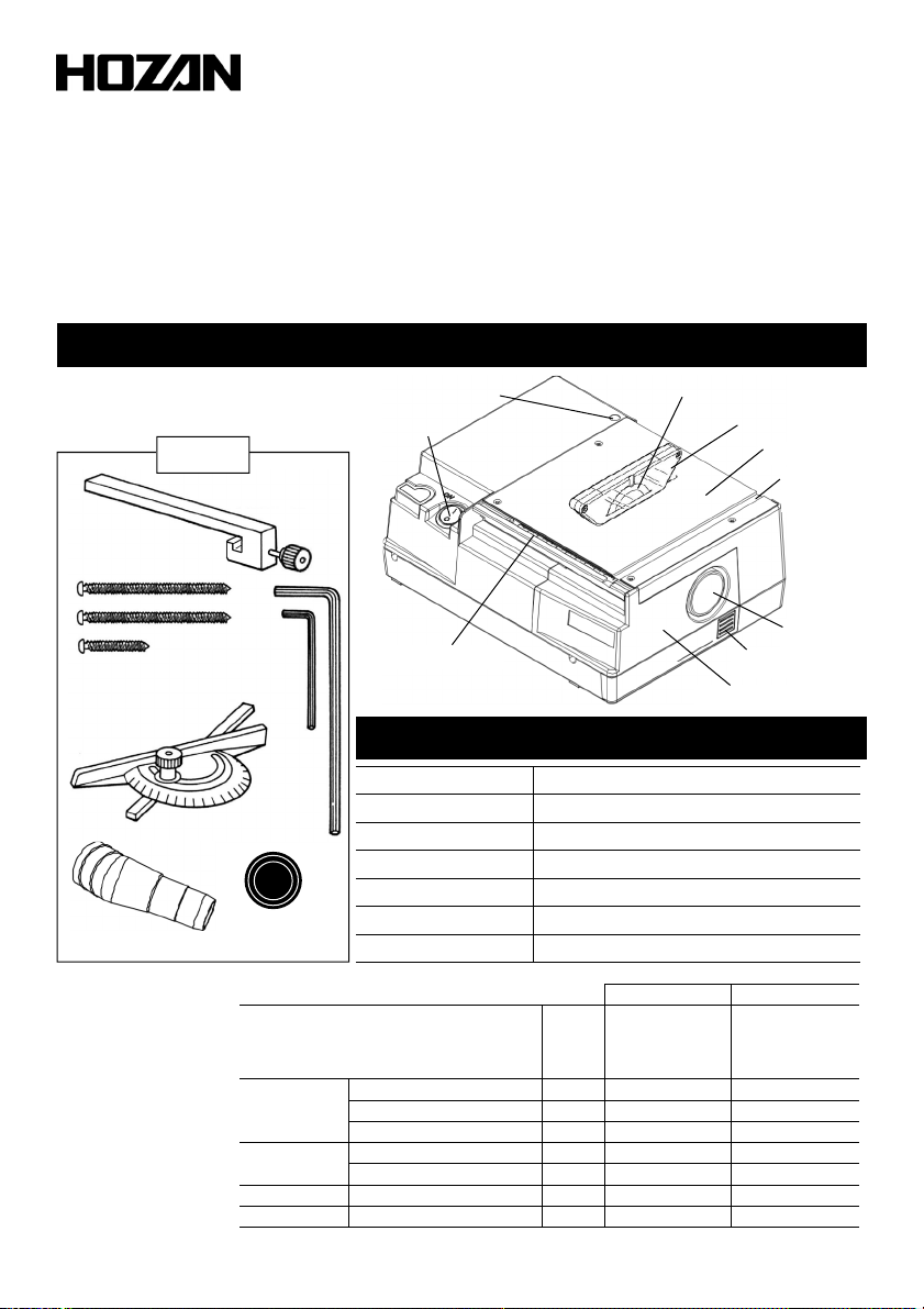
HOZAN K-111-230 User manual

各部
各部各部
各部の
のの
の名称
名称名称
名称と
とと
と入組明細
入組明細入組明細
入組明細
1
11
1
K-111
このたびはホーザン K-111 PCBカッター をお買い上げいただき、まことに りがとうござ
います。この取扱説明書をよくお読みになり、正しくお使いください。また、お読みになった
とも大切に保管してください。
PCB
PCBPCB
PCBカッター
カッターカッター
カッター
取扱説明書
取扱説明書取扱説明書
取扱説明書
仕
仕仕
仕
様
様様
様
回 転 数
標準ディスクカッター
定格電圧・周波数
消費電力
定格時間
外形寸法
重
3500rpm
K-110-1
AC100V 50/60Hz
80W
15分
250(W)×125(H)×190(D)mm
2kg
電源スイッチ
本体固定用穴
安全カバー
ドアロック
作業テーブル
ディスクカッター
( -110-1)
可動スケール
角度ガイド
用溝
集塵口
メンテナンスドア
切断能力
切断能力切断能力
切断能力と
とと
と適応
適応適応
適応ディスクカッター
ディスクカッターディスクカッター
ディスクカッター
◎…最適、○…適、△…可、ー…不適
木材
金属
プリント基板
軟質
アルミ板(純アルミ系)
鉄板(非熱処理)
セラミック
ガラスエポキシ
紙フェノール
2
2
1
1
3
2
板厚
mm
ダイヤモンド
粒度:#150
刃厚:0.8mm
外径:60mmφ
鋸
歯数:100山
刃厚:0.5mm
外径:50mmφ
-
-
○
◎
◎
△
◎
プラスチック アクリル板 2 - ○
◎
△
-
-
○
K
KK
K-
--
-110
110110
110-
--
-1
11
1
K
KK
K-
--
-1
11
110
1010
10-
--
-2
22
2
板材の種類
-110-1は標準付属、
-110-2は別売です。
付属品
付属品付属品
付属品
集塵口アダプター
集塵口
キャップ
平行ガイド
本体固定ネジ3本
六角レンチ
2mm(小)
角度ガイド
六角レンチ
3mm(大)

注意文
注意文注意文
注意文の
のの
の警告
警告警告
警告マークについて
マークについてマークについて
マークについて
ご
ごご
ご使用上
使用上使用上
使用上の
のの
の注意
注意注意
注意
この取扱説明書ではご使用上の注意事項を次のように区別しています。
警告
警告 警告
警告 …重傷をともなう重大事故の発生を想定してのご注意
注意
注意 注意
注意 …傷害や物的損害を想定してのご注意
なお、注意
注意 注意
注意 として記載されていても、 るいは特に記述がなくても、状況によっては重大
な結果をまねく恐れが ります。正しく安全にご使用ください。
2
22
2
1.安全カバーを下げた状態で作業してください。安全カバーを上げたまま作業すると、
使用者がディスクカッター(刃)で傷害を負う恐れが ります。
2.巻き込み事故の防止のため、手袋は絶対に着用しないでください。
3.作業中は保護メガネを使用してください。粉塵の多いところでは、防塵マスクを併用
してください。
4.可燃性の液体やガスの る所で使用しないでください。
警告
警告警告
警告
1.定格時間を超えて連続使用しないでください。
[本機の定格時間:15分]
使用は15分以内とし、必ず使用時間と同じだけ休止してください。
小休止は連続運転と同様です。
2.銘板に表示して る電圧で使用してください。表示を超える電圧で使用すると本機故
障の恐れが ります。
3.切断能力(板厚)を守ってください。能力以上のものを切断すると本機故障の恐れが
ります。
注意
注意注意
注意
本機には集塵口を備えていま
す。お手持ちの紙パック式家
庭用掃除機を接続すると集塵
しながら切断作業ができます。
・
・・
・集塵機
集塵機集塵機
集塵機(
((
(掃除機
掃除機掃除機
掃除機)
))
)の
のの
の取
取取
取り
りり
り付
付付
付け
けけ
け方法
方法方法
方法
集塵口に、付属の集塵口アダプター
を取り付け、掃除機を接続します。
【適合径:32~36mmφ】
集塵機を使用しない場合は、付属の
集塵口キャップで集塵口を塞いでくだ
さい。
非使用時
集塵機使用時
紙パック式家庭用掃除機
準
準準
準
備
備備
備

準
準準
準
備
備備
備
2
22
2
電源スイッチを入れ、切断する材料を手前からゆっくりと
送っていくと切断できます。
1
11
1
安全カバーを下げ、電源スイッチが切れている(スイッチ
上の表示、手前のOが押し込まれている)ことを確かめて
から電源プラグをコンセントに差し込みます。
安全カバー
平らで安定した場所に設置します。
固定ネジの出代(デシロ)は約15mmです。20mm厚以上の作業台に固定してください。
3
33
3
ドアロック
ご
ごご
ご使用方法
使用方法使用方法
使用方法
付属の本体固定ネジを3箇所の本体固
定用穴に通し、作業台などに固定しま
す。
ドアロックを押さえながらメンテナンスドアを手
前に引き抜きます。
必ず作業台に固定して使用してください。固定しないで使用すると設置が不安定に
なり、思わぬ事故につながります。
警告
警告警告
警告
電源スイッチ
なお、7ページに記載の別売クランプを使用して、作業台に穴を開けずに固定すること
もできます。
・切断する材料は最後までしっかりと押さえながら
送ってください。押さえが不十分ですと切断しきっ
た際に材料が手前に飛んでくることが ります。
・ディスクカッターに指などを近づけないよう、十分
に注意して作業してください。
注意
注意注意
注意
2
22
2
1
11
1
長
長
短

4
44
4
ご
ごご
ご使用方法
使用方法使用方法
使用方法
可動
可動可動
可動スケール
スケールスケール
スケール
平行ガイドに可動スケールを併用すると、寸法を決めて切り出す
のに便利です。
作業上の必要に応じて、平行ガイド、可動スケール、角度ガイドを使用してください。
平行
平行平行
平行ガイド
ガイドガイド
ガイド 固定した平行ガイドに材料を当てて らせると、元の辺と平行に切断
できます。
3
33
3
【平行ガイドの取り付け方…ディスク
カッターより右側へ取り付ける場合】
メンテナンスドアを開けて右側からス
ライドさせて取り付け、ツマミを締め
込みます。
【平行ガイドの取り付け方…ディスク
カッターより左側へ取り付ける場合】
テーブル左端に手前から奥へ挿入
し、ツマミを締め込みます。
【
【【
【例
例例
例】
】】
】
長さ4cmのものを複数作るために、材料を
ディスクカッターの左側より差し入れる場合
4cm 4cm 4cm
平行ガイドをディスクカッターの右面
に接するように移動し、軽く固定しま
す。
①
①①
①
ディスクカッター
平行ガイド
平行
平行平行
平行ガイド・
ガイド・ガイド・
ガイド・

5
55
5
ご
ごご
ご使用方法
使用方法使用方法
使用方法
平行ガイドの左辺が可動スケールの4
に合致するように移動し、しっかりと固
定します。
③
③③
③
0 4 ・ ・ ・
材料を左側から差し入れ、平行ガイド
にぴったりと当てた状態で前方へ押す
と、長さ4cmの切断片が得られます。
④
④④
④
平行ガイドをディスクカッターの左側に
設置して、左右逆の操作もできます。
可動スケールの目盛0が平行ガイド
の左辺に合致するようにスライドさせ
ます。
可動スケールの左端近くに指掛りが
りますから移動時にご利用くだ さ
い。
②
②②
②
0
可動スケール
材料
4cm
可動スケールの目盛は目安とお考えになり、実際には正確にケガキした線に沿って
切断してください。また、不要の材料で試し切りをしてご確認ください。
注意
注意注意
注意

ディスク ッターの
ディスク ッターのディスク ッターの
ディスク ッターの交換方法
交換方法交換方法
交換方法
1
11
1 ドアロックを押しながら、メンテナンスドアを開きま
す。
6
66
6
ドアロック
本機に標準付属のディスクカッター(刃)は K-110-1 で、主にプリント基板の切断に適しま
す。金属や木材などを切断する場合、刃が摩耗した場合は1ページの切断能力表を参考
に、切断材料に応じたディスクカッターをお求めのうえ交換してください。
ディスクカッター
交換部品
交換部品交換部品
交換部品
部品はホーザンの通信販売でもお求めいただけます。
外径 mmφ
60
50
品 番
K-110-1
K-110-2
種類
ダイヤモンド(粒度:#150)
鋸
刃厚 mm
0.8
0.5
歯数
-
100山
5
55
5
切断作業終了後は電源スイッチを切り、電源プラグをコンセントから抜きます。
平行ガイドや角度ガイドを使用して、まっすぐに材料を送ってください。途中から曲げ
ると抵抗が増し、ディスクカッターの回転が止まったり、モーターへの負担から故障の
原因になったりします。
注意
注意注意
注意
ご
ごご
ご使用方法
使用方法使用方法
使用方法
角度
角度角度
角度ガ ド
ガ ドガ ド
ガ ド
辺に対し角度を持って切断するときは、角
度ガイドを希望の角度に設定して固定し、
角度ガイドで材料を押すようにして角度ガ
イドの溝をらせると直線が出ます。
平行切断の場合でも平行ガイドと併用する
と操作性、安定性が増します。
小さい材料ではぜひご使用ください。
角度ガイド用溝
角度ガイド
平行ガイド
必ず電源スイッチを切り、電源コードのプラグをコンセントから抜いて交換作業をしてくださ
い。
注意
注意注意
注意

7
77
7
六角レンチ(大)でディスクカッター取り付けネジ
を反時計方向に回してはずし、ディスクカッター
を取りはずします。
3
33
3
ディスクカッターをゆっくりと手で回転させながら、作
業テーブル上の小穴と回転シャフト上の穴を合わ
せ、六角レンチ(小)を差し込み刃が回らないよう固
定します。
2
22
2
取り外しの逆の手順で新しいディスクカッターを
取り付けます。
ディスクカッターの取り付けネジは、しっかりと締
め込んでください。
取り付け後、六角レンチ(小)を忘れずに抜いてく
ださい。
4
44
4
K
KK
K-
--
-111
111111
111-
--
-16
1616
16
クランプ
クランプクランプ
クランプ(
((
(2
22
2個入
個入個入
個入)
))
)
作業台に穴を開けずに本体を
固定できます。20~45mm厚
の作業台に対応します。
オプション
オプションオプション
オプション
オプション
オプションオプション
オプション
ディスク ッターの
ディスク ッターのディスク ッターの
ディスク ッターの交換方法
交換方法交換方法
交換方法
小穴
ディスクカッター
取り付けネジ
拡大
刃の回転方向
本機正面に向かって右方向からの図
Kー110ー2 の場合は刃に方向
性が ります。締め付ける六角
レンチ(大)のほうから見て右写
真のように刃のギザを向けて取
り付けます。

8
88
8
18.09
本社 〒556-0021 大阪市浪速区幸町1-2-12
TEL(06)6567-3111 FAX(06)6562-0024
補修部品については、 eb上のパーツリストをご覧ください。
ホーザン 通信販売 検索
検索検索
検索
通信販売もご利用いただけます。

Identification of parts and contents
1
11
1
K-111-230
Thank you for purchasing the HOZAN K-111-230 CIRCULER SAW. With proper care and
handling, this fine instrument will provide years of trouble-free operation. Please read this
entire instruction manual carefully before attempting to place this instrument in service.
Please keep this instruction manual available for reference.
CIRCULER SAW
Specifications
Revolution speed
Standard disk cutter
Rated voltage
Power consumption
Rated time
External dimensions
Weight
3500 rpm
K-110-1
30 - 40 V~
~~
~ 50/60Hz
80 W
15 minutes
50(W)×1 5(H) 190(D)mm
kg
Power switch
Hole for
securing screw
Safety guard
Lock button
Table
Disk cutter
K-110-1
Movable scale
Dust exhaust
port
Maintenance hatch
Cutting capacity and compatible disk cutter
+++:most suitable, ++:more suitable, +:possible, -:not suitable
K-110-1 is standardly accompanied, K-110- is optional part.
Wood
Metal
PCB
Soft
Steel sheet (w/o heat treatment)
Ceramic
Glass epoxy
Paper phenol
Aluminum sheet (pure aluminum)
Plastic Acrylic board
1
1
3
Sheet
thickness
(mm)
Diamond
grid No.:#150
Blade thickness:0.8mm
Outer dia.: 60mm φ
Saw
Number of teeth: 100
Blade thickness:0.5mm
Outer dia.: 50mm φ
-
-
++
+++
+++
+
+++
- ++
+++
+
-
-
++
K-110-1K-110-2
Sheet material type
集塵口アダプター
集塵口
キャップ
Accessories
Rip fence
3
Securing screws
3mm
Hex key (short)
Miter gauge
3mm
Hex key
(long)
Adapter for dust port Cap for
dust port
INSTRUCTION MANUAL

2
22
2
These symbo s are used throughout the instruction manua to a ert the user to potentia
safety hazards as fo ows :
Warning … Notice when incorrect hand ing cou d cause the user's death or serious
injury.
Caution … Notice when incorrect hand ing cou d cause injury to the user or materia
damage.
Even if the instructions do not have Caution mark, there are some possibi ities for a
serious situation. Fo ow the instructions.
Warning and caution symbols
Precautions
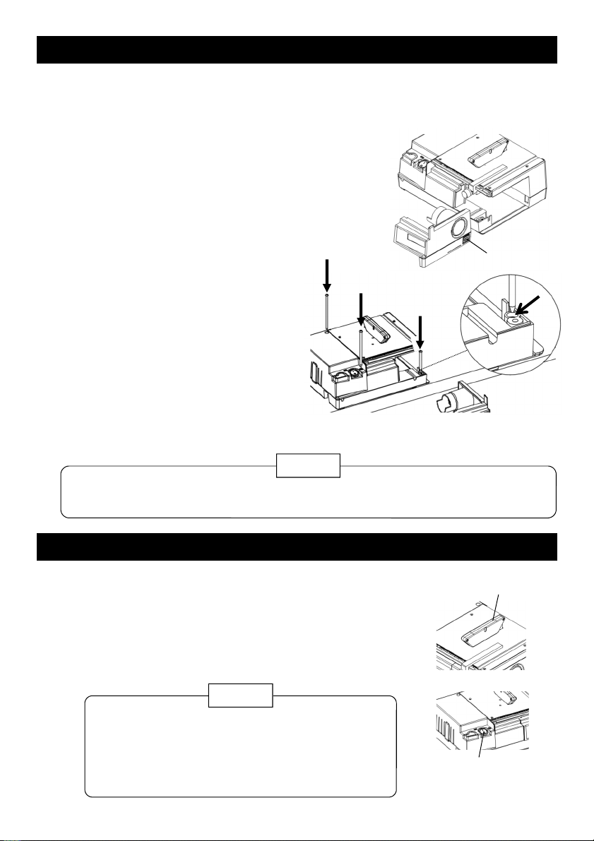
1. A ways ower the safety guard when using. Otherwise, this cou d injure the operator
with the disk cutter (b ade).
2. Do not wear g oves when operating, since they cou d get caught in the moving parts.
3 . Wear safety g asses whi e operating. A dust-proof mask shou d a so be worn in p ace
where there is ots of dust in the air.
4. Do not use in p aces where f ammab e iquids or gases exists.
Warning
1. Do not operate continuous y for onger than the rated time.
[The rated time of K-111-230 is within 15 minutes.]
P ease take an interva of the minutes equiva ent to the operated minutes. A short rest
means the same as a continuous operation.
2. Use on y with the ine vo tages specified on the rating p ate. Use of vo tage higher
rated cou d cause a ma function.
3 . Cut workpieces of thickness under rated. Otherwise, this cou d cause a ma function.
Caution
Preparation
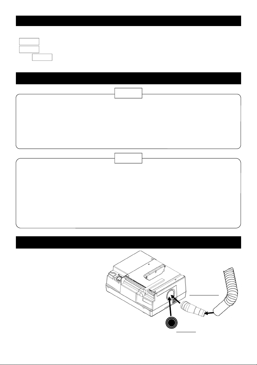
The K-111-230 has a dust port
for exhausting cutting dust.
Attach your paper bag system
vacuum c eaner for domestic
use with “the adapter for dust
port”. [App icab e hose diame-
ter of c eaner: 32 to 36 mmφ]
If not in use of a vacuum c ean-
er, c ose the dust port with “the
cap for dust port”.
Attach a vacuum cleaner
When not in use of
a vacuum cleaner
When using
vacuum cleaner
Vacuum cleaner

Preparation
2
22
2
Turn the power switch on.
Gent y feed the workpiece into the disk cutter.
1
11
1
Connect the power p ug to an out et, after owering the
safety guard and being sure that the power switch is
turned off (indication “O” of which is depressed).
Safety guard
Secure the K-111-230 on a stab e and eve work tab e. The tips of securing screws pro-
trude 15 mm be ow the unit case, so 20 mm or more thickness of the tab e top is neces-
sary.
3
33
3
lock button
Operation
Secure on the work tab e using the pro-
vided three screws through the three
ho es as shown in the i ustration.
Draw the maintenance hatch whi e depressing
the ock button.
Power switch
NOTE: With the optiona c amps mentioned on page7, securing without boring ho es is
possib e.
・Feed the workpiece ho ding tight y ti comp eted.
Otherwise, a cut piece may f y to your side.
・Do not bring your fingers c ose to the disk cutter.
Caution
A ways use in a secured state. Otherwise, an unexpected accident wi be occurred
due to unstab e setting.
Warning
2
22
2
1
11
1
Long
Short
Long

4
44
4
Operation
Uti ize the rip fence, the miter gauge and movab e sca e as the need arises.
Rip fence
The workpiece fed a ong the rip fence is cut in para e .
3
33
3
[How to attach the rip fence at the
right side of the disk cutter]
Open the maintenance hatch and
insert from the right, and secure the
screw.
[How to attach the rip fence at the
eft side of the disk cutter]
Insert from the eft end of the tab e
and secure the screw.
[Examp e]
Feed the workpiece from the eft side of the
disk cutter for cut some pieces in 4 cm
4 cm 4 cm 4 cm
Move the rip fence to touch the right
face of the disk cutter and screw the
knob moderate y.
①
①①
①
Rip fence and
movable scale
Uti ize the movab e sca e with the rip fence for cutting in the
specified size.
Disk cutter
Rip fence

5
55
5
Operation
Move the rip fence so that its eft edge
contacts “4” graduation and secure
tight y.
③
③③
③
0 4 ・ ・ ・
Feed the workpiece a ong the rip
fence to cut in 4 cm.
④
④④
④
S ide the movab e sca e so that its “0”
graduation contacts the eft edge of
the rip fence.
Using the knob near the eft end is
recommended for s iding easi y.
②
②②
②
0
Movable scale
4 cm
Workpiece
The movab e sca e is to be used on y as a guide, In an actua operation, cutting a ong
a ine drawn on the workpiece beforehand is high y recommended.
Caution
If setting the rip fence at the eft side
of the disk cutter, operation in sym-
metrica ayout can be done.
NOTE:

1
11
1 Open the maintenance hatch pushing the ock button.
6
66
6
Lock button
5
55
5
Turn the power switch off and disconnect the power p ug after the work is finished.
Operation
Miter gauge
When cutting with a certain ang e, use the
miter gauge. Push the workpiece with the
miter gauge of desired ang e a ong the
groove for miter gauge.
A so cutting in para e can be done con-
venient y by using the miter gauge with the
rip fence if the workpiece is sma enough.
Groove for
miter gauge
Miter gauge
Rip fence
Feed the workpiece straight by using the rip fence and the miter gauge. If feeding to
tortuous direction, the oad torque increases to cause the motor to be stopped or bro-
ken.
Caution
Replacing the disk cutter
The provided disk cutter (b ade) K-110-1 is appropriate for cutting PCBs. To cut meta and
wood, or when the disk cutter has worn, rep ace with anther disk cutter or a new disk cutter
according to the cutting performance tab e on page 1.
Disk cutter
Replacement parts
Part no. Type
K-110-2
K-110-1
Saw 50
60 0.8
0.5
100 teeth
-
Be sure to turn the power switch off and disconnect the power p ug from the out et.
Caution

Attach a new disk cutter in the reverse
procedures of detaching.
4
44
4
Remove the disk cutter fixing screw, turning
counterc ockwise with the hex key ( ong). Then,
remove the disk cutter.
3
33
3
Insert the hex key (short) into the ho e on the shaft
through the ho e on the tab e to ho d the shaft not to
be turned.
2
22
2
K-111-16 Clamps (2 pcs)
Can be set without tapping the
work tab e. Needs 20 to 45 mm
thickness of the worktab e top.
Option
Option
7
77
7
Replacing the disk cutter
Hole
Disk cutter fixing screw
Tighten the disk cutter fixing screw secure y.
Remember to remove the hex key (short).
Revolving direction
View from maintenance hatch opened
enlarged
NOTE:
The K-110-2’s teeth have direction
corresponding to the revo ving
direction. Attach as shown in the
photo.

1--1 Saiwaicho, Naniwa-ku, Osaka 556-00 1, Japan
Tel : +81-6-6567-3111 F a x : +81-6-656 -00 4
8
88
8
18.19
Table of contents