Maintenance
The Hozelock Cyprio range of
Aquaforce pumps have been designed
to allow fast and easy maintenance. To
prolong the life of your pump and
keep your pump in peak condition,
you should follow these maintenance
guidelines.
Caution: Always unplug or disconnect
ALL appliances in the pond from the
electricity supply before putting your
hands in the water or starting
maintenance.
1. When the pump is newly installed,
you should check your pump daily that
it is performing correctly.
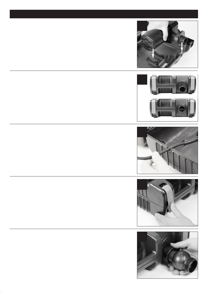
2. If you notice a drop in performance
(low flow) you should clean the
strainer cage. Cleaning intervals will
vary depending on the condition of
your pond’s water. This could be as
often as weekly in the summer
months. To clean the strainer cage,
open the clips and remove the pump.
The cage can then be wiped clean of
debris blocking the strainer holes and
washed in clean water. You should
also check that the pump chamber &
rotor are not blocked with debris.
3. At least once a year you should
completely disassemble the pump
including the rotor assembly as
described below and wash all
components in clean, fresh water.
Replace worn or broken parts.
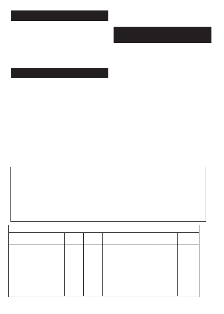
Pump Dismantling & Assembly
(6000 & 8000) - Fig 22
1. Switch off the pump and remove
the strainer cage as described above
and remove the pump.
2. Ensure the pump is cool before
dismantling it.
3. Unscrew the 3 posidrive screws in
the chamber.
4. ently pull the pump chamber (d)
squarely away from the motor body
(a).
5. Pull the rotor assembly (c) out of
the motor body. Important! Take
extra care so as to not drop the
rotor assembly.
6. Wash out all of the components in
clean water. Do not use detergents
or other chemical cleaners.
7. Ensure the o-ring (b) is on it’s seat
(fig 29). Replace the rotor assembly
into the motor body, ensuring that
the holes in the plate behind the
impeller locate onto the pins on the
motor body. Refit the pump
chamber and screws and return the
pump to the strainer cage.
Pump Dismantling & Assembly
(12000 & 15000) - Fig 23
1. Switch off the pump and remove
the strainer cage as described above
and remove the pump.
2. Ensure the pump is cool before
dismantling it.
3. Unscrew the 4 posidrive screws in
the chamber.
4. Rotate the pump chamber (d) as
far as it will go and gently pull the
chamber squarely away from the
motor body (a).
5. Pull the rotor assembly (c) out of
the motor body.
Important! Take extra care so as to
not drop the rotor assembly.
6. Wash out all of the components in
clean water. Do not use detergents
or other chemical cleaners.
7. Ensure the o-ring (b) is on it’s seat
(fig 24). Replace the rotor assembly
into the motor body, ensuring that
the holes in the plate behind the
impeller locate onto the pins on the
motor body. Refit the pump
chamber and screws and return the
pump to the strainer cage.
4. If you live in a hard water area
(water with high levels of calcium or
limescale content), the pump, rotor
assembly and steel can should be
cleaned at regular intervals. The
cleaning interval required will vary
depending on the hardness of your
water, so you should inspect for signs
of calcium build up regularly.
To clean off calcium or limescale
deposits a small nylon bristled brush
(such as a toothbrush) may be used.
Dismantle the pump as described
above and remove the rotor. Clean the
limescale deposits from the rotor using
fresh clean water
If excessive calcium deposits build up,
the thermal overload protection may
be activated (See INTRODUCTION).
d
c
b
a
d
c
b
a
24
22
23
6000/8000
12000/15000