HP 5501B Service manual

Errata
Title & Document Type: HP5501B Laser Head Operating & Service Manual
Manual Part Number: 05501-90035
Serial Prefixes: 2632
Revision Date: September 1986
HP References in this Manual
This manual may contain references to HP or Hewlett-Packard. Please note that Hewlett-
Packard's former test and measurement, semiconductor products and chemical analysis
businesses are now part of Agilent Technologies.
Changes to this Manual
No changes have been made to this manual, with the exception of correcting the odd
spelling and grammatical errors. In some places original photographs may be replaced
or augmented with modern digital photographs. (it’s weird looking at an old BW HP
manual and seeing a color photograph… still gets me)
About this Manual
This manual is reproduced from high-resolution scans of an original document, which
was then converted to Word format using custom designed OCR software for my
personal use.
This means that what you see here is not a scan of a scan/copy.
OCR errors may exist and as such the user of this document should take care and use
common sense when referencing this documentation.
Copyright Notice
This documentation is © Copyright 1980 Hewlett Packard and © Copyright 2006, Jack Hudler,
Permission to use and redistribute this documentation for non-commercial and internal corporate
purposes is hereby granted, free of charge.
Any redistribution of this documentation or its derivates must include this copyright notice.
You may not sell this documentation or its derivations without written consent.
You may modify this documentation as necessary, but you may not sell derivative works based
on it.
You may include this documentation with the equipment/hardware on which it is used for the
purposes of selling the equipment/hardware. If you advertise that a copy of this documentation is
included in the sale, you must state that is for “Free”.
Meaning if you want to gratuitously toss in a copy of the manual on an eBay sale, it’s ok with me
as long as you state it’s for free. No you can’t sell a digital archive of manuals and say it includes
a free copy of this documentation. You must give it away with equipment.
I think you get the spirit of the copyright; it takes a lot of hours to scan and replicate a manual. I
just want this used in the spirit in which is it given.
Agilent if you have questions or wish to include this in your archive email me.

ii

OPERATING AND SERVICE MANUAL
HP5501B
LASER HEAD
SERIAL NUMBER PREFIX: 2632A
This manual applies directly to HP5501B Laser Heads
with serial numbers prefixed 2632A. Lower number serial
prefixes are covered in Section 7 while higher number
serial prefixes are documented with "Manual Changes"
Supplements described in Section 7.
© HEWLETT-PACKARD COMPANY 1986
5301 Stevens Creek Blvd., Santa Clara, CA 95051-7299
Portions © by Jack Hudler 2006
MANUAL PART NUMBER 05501-90035
Microfiche Part Number 05501-90036 Printed: SEPTEMBER 1986

ii
ELECTRICAL SAFETY CONSIDERATIONS
GENERAL
The product and related documentation must be reviewed for
familiarization with safety markings and instructions before
operation.
This product is a Safety Class I instrument (provided with a
protective earth terminal).
BEFORE APPLYING POWER
Verify that the product is set to match the available line voltage
and the correct fuse is installed. Refer to Section 2, Installation.
SAFETY EARTH GROUND
An uninterruptible safety earth ground must be provided from
the main power source to the product input wiring terminals,
power cord, or supplied power cord set.
SAFETY SYMBOLS
Instruction manual symbol: the product
will be marked with this symbol when it
is necessary for the user to refer to the
instruction manual.
Indicates hazardous voltages.
Indicates earth (ground) terminal.
The WARNING sign denotes a hazard. It
calls attention to a procedure, practice,
or the like, which, if not correctly
performed or adhered to, could result in
personal injury. Do not proceed beyond
a WARNING sign until the indicated
conditions are fully understood and met.
The CAUTION sign denotes a
hazard. It calls attention to an
operating procedure, practice, or the
like, which, if not correctly performed
or adhered to, could result in
damage to or destruction of part or
the entire product. Do not continue
beyond a CAUTION sign until the
indicated conditions are fully
understood and met.
Any interruption of the protective (grounding) conductor (inside
or outside the instrument) or disconnecting the protective earth
terminal will cause a potential shock hazard that could result in
personal Injury. (Grounding one conductor of a two conductor
outlet is not sufficient protection).
Whenever it is likely that the protection has been impaired, the
instrument must be made inoperative and be secured against
any unintended operation.
If this instrument is to be energized via an autotransformer (for
voltage reduction) you must make sure the common terminal is
connected to the neutral (earthed pole) of the power source.
Servicing instructions are for use by service-trained personnel
only. To avoid dangerous electric shock, do not perform any
servicing unless qualified to do so.
Adjustments described in the manual are performed with power
supplied to the instrument while protective covers are removed.
Energy available at many points may, if contacted, result in
personal injury.
Capacitors inside the instrument may still be charged even if the
instrument has been disconnected from its source of supply.
For continued protection against the fire hazard, replace the line
fuse(s) only with 125V fuse(s) of the same current rating and
type (for example, normal blow, time delay, etc.). Do not use
repaired fuses or short circuited fuse holders.
From 1.2 kilovolts to 12 kilovolts dc is present on the anode of
the laser tube in the 5501B. Exercise extreme caution when
working inside the instrument. The high voltage could cause
serious personal injury if contacted. Any adjustments performed
should be by service trained personnel only.
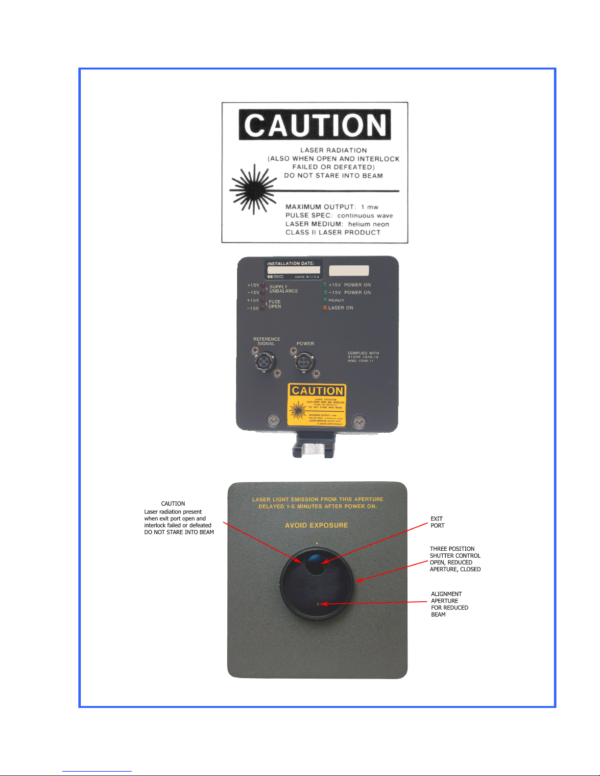
LASER HEAD SAFETY CONSIDERATIONS
LASER RADIATION IS EMITTED FROM THE APERTURE ON THE 5501B LASER HEAD AS
ILLUSTRATED ON THE FOLLOWING PAGE. DO NOT STARE INTO BEAM. THIS PRODUCT IS A
CLASS II LASER PRODUCT CONFORMING TO U.S. NATIONAL CENTER FOR DEVICES AND
RADIOLOGICAL HEALTH REGULATIONS 21 CFR 1040.10 AND 1040.11. THE MAXIMUM RADIANT
POWER OUTPUT IS 1 MILLIWATT, THE PULSE SPECIFICATION IS CONTINUOUS WAVE, THE
LASER MEDIUM IS HELIUM-NEON, AND THE WAVELENGTH IS 632.991 NANOMETRES.
LASER RADIATION IS ACCESSIBLE WHEN THE 5501B COVERS ARE REMOVED AND THE TEST-
NORM SWITCH, A1S2, IS IN THE TEST POSITION.
USE OF CONTROLS OR ADJUSTMENTS OR PERFORMANCE OF PROCEDURES OTHER THAN
THOSE SPECIFIED HEREIN MAY RESULT IN HAZARDOUS RADIATION EXPOSURE.

iii
LASER HEAD SAFETY LABELS

iv
END PRODUCT LASER SAFETY
CONSIDERATIONS
The 5501B Laser Head complies with U.S. National Center for
Devices and Radiological Health regulations 21 CFR 1040.10 and
1040.11.
These regulations may also apply to the end product into which
the 5501B will be designed. Care must be taken to insure that the
end product complies with all applicable national and local laser
safety regulations.

Table of Contents
v
1GENERAL INFORMATION ...................................................................................................................1-2
1-1. Introduction ..............................................................................................................................1-2
1-4. Equipment Description ............................................................................................................1-2
1-8. Manual Organization................................................................................................................1-3
1-10. Instruments covered by this manual........................................................................................1-3
1-14. Safety Considerations..............................................................................................................1-4
1-16. Equipment Supplied ................................................................................................................1-4
1-18. Available Accessories ..............................................................................................................1-4
1-20. Specifications...........................................................................................................................1-5
1-22. Recommended Test Equipment..............................................................................................1-6
1-24. Warranty...................................................................................................................................1-6
2INSTALLATION.....................................................................................................................................2-1
2-1. Introduction ..............................................................................................................................2-1
2-3. Unpacking, Inspection, and Reshipment.................................................................................2-1
2-5. Unpacking and Inspection.......................................................................................................2-1
2-7. Warranty Claims.......................................................................................................................2-1
2-9. Laser Tube Shipment...............................................................................................................2-1
2-11. Tagging for Service..................................................................................................................2-2
2-13. Packaging for Reshipment.......................................................................................................2-2
2-14. Installation ................................................................................................................................2-2
2-16. System Cabling........................................................................................................................2-2
2-19. Power and Signal Connections................................................................................................2-5
2-21. Cable Fabrication.....................................................................................................................2-5
2-23. Grounding Considerations.......................................................................................................2-7
2-25. Power Supply Requirements ...................................................................................................2-7
2-27. Power Dissipation ....................................................................................................................2-7
2-29. Fusing.......................................................................................................................................2-7
2-31. Dimensions ..............................................................................................................................2-8
2-33. Mounting and Fixturing ............................................................................................................2-9
3OPERATION.......................................................................................................................................3-10
3-1. Introduction ............................................................................................................................3-10
3-4. Power Application ..................................................................................................................3-10
3-6. HP5501B Laser Head Front Panel Controls ..........................................................................3-10
3-8. HP5501B LASER HEAD REAR PANEL INDICATORS AND CONNECTORS .........................3-11
3-10. OPERATING MODES.............................................................................................................3-13
3-12. Warmup Time Operating Notes .............................................................................................3-14
3-13. HP 10740A Coupler Based Systems - Manual Monitoring....................................................3-14
3-14. Systems with HP10745A or HP10746A Cards - Automatic Monitoring .................................3-14
3-16. HP10740A Coupler - Error Signal Information.......................................................................3-14
3-17. HP10746A Error Signal Processing .......................................................................................3-15
3-18. HP 10745A Background Information .....................................................................................3-15
3-19. Program Modifications...........................................................................................................3-15
4PERFORMANCE TESTS ......................................................................................................................4-1
4-1. Introduction ..............................................................................................................................4-1
4-3. RECOMMENDED TEST EQUIPMENT .....................................................................................4-1
4-5. TEST RECORD.........................................................................................................................4-1
4-7. HP5501B PERFORMANCE TEST ............................................................................................4-1
4-9. Input Voltage Check.................................................................................................................4-1
4-11. Laser Power Output Test .........................................................................................................4-1
4-13. Procedure.................................................................................................................................4-2

Table of Contents
vi
5ADJUSTMENTS....................................................................................................................................5-1
5-1. Introduction ..............................................................................................................................5-1
5-3. Safety Considerations..............................................................................................................5-1
5-5. Recommended test equipment ...............................................................................................5-1
5-7. Factory Selected Components ................................................................................................5-1
5-9. Adjustment Procedures............................................................................................................5-2
5-11. Reference Temperature Adjustments ......................................................................................5-2
5-14. Preliminary Procedure..............................................................................................................5-2
5-17. Laser Tube Current Adjustment...............................................................................................5-4
6REPLACEABLE PARTS........................................................................................................................6-1
6-1. Introduction ..............................................................................................................................6-1
6-4. Exchange Assemblies..............................................................................................................6-1
6-6. ABBREVIATIONS AND REFERENCE DESIGNATIONS ...........................................................6-1
6-8. ORDERING INFORMATION .....................................................................................................6-1
6-11. DIRECT MAIL ORDER SYSTEM...............................................................................................6-2
6-14. Exploded View........................................................................................................................6-11
7MANUAL CHANGES ............................................................................................................................7-1
7-1. Introduction ..............................................................................................................................7-1
7-3. Newer Instruments ...................................................................................................................7-1
8SERVICE ..............................................................................................................................................8-1
8-1. Introduction ..............................................................................................................................8-1
8-3. Theory of Operation .................................................................................................................8-1
8-5. Recommended Test Equipment ..............................................................................................8-1
8-7. Service Aids..............................................................................................................................8-1
8-9. Schematic Diagram Symbols and Reference Designations....................................................8-1
8-12. Safety Considerations..............................................................................................................8-3
8-14. Safety Symbols ........................................................................................................................8-4
8-16. Before and After Service Product Safety Checks ....................................................................8-5
8-18. LASER HEAD BLOCK DIAGRAM DESCRIPTION ....................................................................8-5
8-26. Laser Tuning ............................................................................................................................8-7
8-29. Warmup Mode Tuning .............................................................................................................8-7
8-34. Optical Mode Tuning................................................................................................................8-9
8-40. Laser Assembly Optics ..........................................................................................................8-12
8-42. Reference Receiver ................................................................................................................8-12
8-44. Shutter Mechanism ................................................................................................................8-12
8-46. ASSEMBLY/SCHEMATIC LOCATIONS OF HP5501B BLOCK DIAGRAM ELEMENTS .........8-12
8-47. REAR PANEL LED INDICATORS ...........................................................................................8-12
8-52. ASSEMBLY REMOVAL INSTRUCTIONS ...............................................................................8-14
8-62. TROUBLE ISOLATION ...........................................................................................................8-19
8-63. Quick Tuning Checkout Procedure .......................................................................................8-19
8-67. Testing the Liquid Crystal Switch...........................................................................................8-21
8-70. HP5501B Trouble Isolation Procedures.................................................................................8-23
8-72. Procedure...............................................................................................................................8-24
8-73. A1 CONNECTOR BOARD CIRCUIT THEORY........................................................................8-26
8-76. High Voltage Power Supply Switch (A1Q3 and A1Q4)..........................................................8-26
8-79. Power Distribution..................................................................................................................8-26
8-83. A1 CONNECTOR BOARD TROUBLESHOOTING..................................................................8-27
8-85. Rear Panel LED Operational Check.......................................................................................8-27
8-87. A2 HIGH VOLTAGE POWER SUPPLY CIRCUIT THEORY.....................................................8-29
8-89. HIGH VOLTAGE POWER SUPPLY TROUBLESHOOTING ....................................................8-29
8-91. A3 CONTROLLER/REFERENCE BOARD AND A4 SAMPLER BOARD CIRCUIT THEORY ...8-32
8-92. Introduction ............................................................................................................................8-32
8-95. Clock Ⓐ..................................................................................................................................8-32

Table of Contents
vii
8-97. Dividers Ⓑ..............................................................................................................................8-32
8-99. State Machine Ⓕ....................................................................................................................8-33
8-105. Liquid Crystal Ⓓ.....................................................................................................................8-34
8-109. Photodiode and Amplifier Ⓔ..................................................................................................8-34
8-111. Warmup Error Amplifier and Comparator Ⓙ.........................................................................8-34
8-114. Subtracting Sample and Hold Ⓗ...........................................................................................8-34
8-118. A1/A3 Power Amplifier Ⓘ.......................................................................................................8-35
8-121. Reference Receiver Ⓛ...........................................................................................................8-36
8-125. Line Driver Ⓚ..........................................................................................................................8-36
8-127. Power-On Reset (POR) Ⓖ......................................................................................................8-36
8-129. Laser Head Power Ⓒ.............................................................................................................8-36
8-131. A4 Sampler Board..................................................................................................................8-36
8-133. A3 CONTROLLER/REFERENCE BOARD TROUBLESHOOTING..........................................8-37
8-135. Standard Troubleshooting Procedures .................................................................................8-37
8-137. Digital Troubleshooting..........................................................................................................8-38
8-140. Photodiode and Amplifier Troubleshooting...........................................................................8-41
8-142. Liquid Crystal Troubleshooting..............................................................................................8-42
8-144. Subtracting Sample and Hold Troubleshooting ....................................................................8-42
8-146. Power Amplifier Troubleshooting...........................................................................................8-44
8-148. Warm-Up Error Amplifier Troubleshooting ............................................................................8-46
8-150. Power Supply Troubleshooting .............................................................................................8-46
8-152. Reference Receiver Troubleshooting.....................................................................................8-47
9SERVICE NOTES .................................................................................................................................9-1
9-1. Service Note 5501-02A July 2001............................................................................................9-1

List of Figures
viii
Figure 1-1 HP5501B Laser Head..................................................................................................................1-1
Figure 2-1. HP 107788 Power Cable ............................................................................................................2-3
Figure 2-2. HP 107798 Reference Cable......................................................................................................2-4
Figure 2-3. Typical Transducer System Interconnections............................................................................2-5
Figure 2-4. Interconnecting Plug Details ......................................................................................................2-5
Figure 2-5. HP 5501B Laser Head Interconnect Wire Fabrication ...............................................................2-6
Figure 2-6. Mounting Details and Physical Characteristics..........................................................................2-8
Figure 3-1. HP5501B Front Panel Controls ................................................................................................3-10
Figure 3-2. HP5501B Rear Panel Connectors and Indicators....................................................................3-11
Figure 3-2. HP5501B Rear Panel Connectors and Indicators (Continued)................................................3-12
Figure 4-1. HP5501B Power Connection......................................................................................................4-2
Figure 5-1. A 1 Connector Board, TEST-NORM Switch and Adjustment Locations....................................5-2
Figure 5-2. A3 Controller/Ref Board, Jumpers, Test Points, and Adjustment Locations .............................5-3
Figure 5-3. 55018 High Voltage Areas and Anode Lead..............................................................................5-5
Figure 6-1. HP5501B Laser Head Exploded View......................................................................................6-11
Figure 8-1. Schematic Diagram Notes..........................................................................................................8-2
Figure 8-2.HP5501B Laser Head Block Diagram .........................................................................................8-6
Figure 8-3. Flow Diagram for State Machine................................................................................................8-7
Figure 8-4. Feedback Loop during Warmup Mode......................................................................................8-8
Figure 8-5. Warmup Mode Timing Diagram .................................................................................................8-9
Figure 8-6. Feedback Loop During Optical Mode........................................................................................8-9
Figure 8-7. A6 Sampler Assembly, Exploded View ....................................................................................8-10
Figure 8-8. Liquid Crystal Timing Diagram (Optical Mode)........................................................................8-11
Figure 8-9. Logic Clip Monitoring of Test IC U9 .........................................................................................8-14
Figure 8-10. HP5501B Front Panel and Side Cover Removal....................................................................8-16
Figure 8-11. Factory-adjusted Sampler Mount (MP1) ................................................................................8-18
Figure 8-12. Laser Tube Tuning Characteristics.........................................................................................8-19
Figure 8-13. Quick Tuning Check Test Setup ............................................................................................8-20
Figure 8-14. Quick Tuning Check Waveform Display.................................................................................8-21
Figure 8-15. Liquid Crystal Removal...........................................................................................................8-21
Figure 8-16. Liquid Crystal Test Setup .......................................................................................................8-22
Figure 8-17. HP5501B TEST-NORM Switch A1S2 .....................................................................................8-23
Figure 8-18. High Voltage Power Supply, Schematic Diagram..................................................................8-31
Figure 8-19. State Machine Timing Diagram..............................................................................................8-33
Figure 8-20. Test Point 11 Waveform (HEATER SENSE)...........................................................................8-44
Figure 8-21. E-REF [U20 (Pin 9)]................................................................................................................8-45
Figure 8-22. REFerence Signal Waveforms................................................................................................8-47
Figure 8-23. A1 Connector Board Component Locator .............................................................................8-50
Figure 8-23. A1 Connector Board Component Schematic Diagram..........................................................8-51
Figure 8-23. A1 ↔A3 Connector Pin Table................................................................................................8-52
Figure 8-24. A3 Controller/Reference Board (05501-60027) and A4 Sampler Board (05501-60029)
Schematic Diagram (Sheet 1 of 2)..............................................................................................................8-55
Figure 8-24. A3 Controller/Reference Board (05501-60027) and A4 Sampler Board (05501-60029)
Schematic Diagram (Sheet 2 of 2)..............................................................................................................8-56
Figure 8-24 A3 Controller/Reference Board and A4 Sampler Board Photos & Data ....................................57

List of Tables
ix
Table 1-1. HP5501B Laser Head Specifications and Performance Characteristics.....................................1-5
Table 1-2. Recommended Test Equipment..................................................................................................1-6
Table 2-1. Laser Head System Signal Chart.................................................................................................2-6
Table 2-2. HP 5501B Power Supply Requirements......................................................................................2-7
Table 3-1. Proper 55018 Rear Panel LED Power-up Sequence.................................................................3-13
Table 3-1. Program Modifications for Table 4-12 in the HP5501A System Manual ...................................3-16
Table 3-2. Program Modifications for Table 4-13 in the HP5501A System Manual ...................................3-17
Table 3-3. Modified HP10745A HP-IB Interface Program...........................................................................3-18
Table 3-4 Modified HP10746A Binary Interface Program...........................................................................3-19
Table 4-1. Input Voltage................................................................................................................................4-1
Table 6-1. Exchange Assemblies .................................................................................................................6-1
Table 6-2. Reference Designations and Abbreviations ................................................................................6-3
Table 6-3. HP5501B Board Assemblies Replaceable Parts .........................................................................6-4
Table 6-3. HP5501B Board Assemblies Replaceable Parts (Continued).....................................................6-5
Table 6-3. HP5501B Board Assemblies Replaceable Parts (Continued).....................................................6-6
Table 6-3. HP5501B Board Assemblies Replaceable Parts (Continued).....................................................6-7
Table 6-3. HP5501B Board Assemblies Replaceable Parts (Continued).....................................................6-8
Table 6-3. HP5501B Board Assemblies Replaceable Parts (Continued).....................................................6-9
Table 6-3. HP5501B Miscellaneous Chassis Parts (Continued) ................................................................6-10
Table 6-4. Manufacturer's Code List...........................................................................................................6-12
Table 8-1. A3 U9 Test IC Signal Summary .................................................................................................8-13
Table 8-2. DC Unbalanced Failures............................................................................................................8-26
Table 8-3. IC A3U4 and A3U6 Divider Check .............................................................................................8-39
Table 8-4. Signature Table..........................................................................................................................8-41
Table 8-5. Voltage Testpoints and Limits ...................................................................................................8-46
Table 8-6. A3U17 Reference Receiver Test Voltages.................................................................................8-48


HP5501B
Installation
1-1
Figure 1-1 HP5501B Laser Head

HP5501B
Installation
1-2
1GENERAL INFORMATION
1-1. Introduction
1-2. This Operating and Service Manual contains information required to install, operate, test, adjust,
and service the Hewlett-Packard Model 5501B Laser Head. The information in this manual is
specific to the HP5501B and supplements other publications available for Hewlett-Packard Laser
Transducer products. Also available is the HP5501A Laser Transducer System Manual (HP Part
Number 05501-90028) that describes how to setup, align, and use the laser system to make
interferometer measurements.
1-3. The HP part number of this manual is listed on the title page. Also listed is a microfiche part
number for ordering 4 X 6" microfilm transparencies of this manual. The microfiche package also
includes the latest "Manual Changes" supplement and any pertinent Service Notes.
1-4. Equipment Description
1-5. The HP5501B Laser Head consists of a thermally-tuned laser tube, control circuits, a reference
receiver, and a high-voltage power supply. The laser head requires ±15 Volt supplies, each with
a minimum capacity of 1 Amp. The HP5501B produces a frequency stabilized laser beam, a
balanced reference output (see paragraph 16), a +15 Volt fused output, and a +5 Volt output.
Diagnostic LED’s, mounted on the 5501B's rear panel, provide status information on power
supply input (±15 Volts), fuses, laser output and tuning, and the reference frequency output.
1-6. The 5501B laser beam consists of two linearly polarized and mutually perpendicular (orthogonal)
components separated in frequency by approximately 1.8 MHz. The two components have light
frequencies of F1 and F2. The higher frequency component (F2) is oriented parallel to the laser
base, while the lower frequency component (F1) is perpendicular to the laser base. An optical
receiver inside the HP5501B detects the 1.8 MHz frequency difference and places it at the rear
panel REFERENCE SIGNAL connector as a balanced output (called the REFerence Frequency).
The reference output is one signal used by the external electronics to measure distance traveled.
1-7. During a typical measurement application, the laser beam travels through external optics where
the horizontal and vertical components of the beam are separated. One component travels along
a fixed path and returns to an external optical receiver. The other component travels along the
path (axis) to be measured and then returns to the external receiver. The external receiver
detects the frequency difference between the two components and outputs a signal called the
MEASure Frequency. The MEASure Frequency from the external receiver and the REFerence
Frequency from the laser head are compared by external, customer selected electronics. If the
distance between the external optics is fixed, the MEASure and REFerence frequencies are
equal. As the relative distance between the external optics changes, the MEASure Frequency
changes due to a Doppler frequency shift. This relative change between the MEASure and
REFerence Frequencies is used by the system electronics to compute distance traveled. The
laser transducer system can be configured for computer control of open- and closed-loop
positioning and measuring applications, having single or multiple axes. For more detailed
information, refer to the HP5501A Laser Transducer System manual (HP Part Number 05501-
90028).

HP5501B
Installation
1-3
1-8. Manual Organization
1-9. This Service Manual is organized as follows:
SECTION 1, GENERAL INFORMATION: covers Equipment Description, Manual Organization,
Instruments Covered by this Manual, Safety Considerations, Equipment Supplied, Available
Accessories, Specifications, Recommended Test Equipment, and Warranty Information.
SECTION 2, INSTALLATION: covers Grounding Considerations, Power Requirements, Interconnecting
Cabling, Operating and Storage Environments, Storage and Shipment, and Packaging.
SECTION 3, OPERATION: provides operating information and covers Equipment Front and Rear Panel
Features, Warm-up Time Considerations, and Program Notes.
SECTION 4, PERFORMANCE TESTS: provides Safety Considerations, Performance Tests, and a Test
Record.
SECTION 5, ADJUSTMENTS: covers Safety Considerations, Test Equipment Required, Adjustment
Procedures, and an Adjustment Record.
SECTION 6, REPLACEABLE PARTS: includes Tables of Replaceable Parts including illustrated parts
breakdowns of chassis and mechanical assemblies, Abbreviations, Ordering Information, and
the HP Direct Mail Order System.
SECTION 7, MANUAL CHANGES: describes how to update or backdate the manual for prefixes other
than those listed on the title page.
SECTION 8, SERVICE: contains Safety Considerations, Theory and Block Diagram Descriptions,
Trouble Isolation, Troubleshooting, Schematics, and Component Locations.
1-10. Instruments covered by this manual
1-11. Attached to each instrument is a serial plate. The serial number is in the form: OOOOAOOOOO.
It is in two parts; the first four digits and the letter are the serial number prefix and the last five
digits are the suffix. The prefix is the same for all identical instruments; it changes only when a
change is made to the instrument. The suffix is assigned sequentially and is unique to the
individual instrument. This manual applies to instruments with the serial number prefix listed on
the title page of this manual.
1-12. An instrument manufactured after the printing of this manual may have a serial number prefix
that is not listed on the title page. This unlisted serial number prefix indicates the instrument is
different from those described in this manual. The manual for this newer instrument is
accompanied by a yellow "Manual Changes" supplement. This supplement contains updating
information that explains how to change the manual to be applicable to newer instruments.
1-13. In addition to the new serial number prefix change information, the supplement may contain
information for correcting errors in the manual (errata). To keep this manual as current and as
accurate as possible, Hewlett-Packard recommends that you periodically request the latest
"Manual Changes" supplement. The supplement for this manual is identified with the manual
print date and part number, both of which appear on the manual title page. Complementary
copies of the supplement are available.

HP5501B
Installation
1-4
1-14. Safety Considerations
1-15. The HP5501B Laser Head is designed to receive its power from a Safety Class 1 product. It is
designed and tested in accordance with international safety standard IEC* 348. It is also a Class
1/ Laser product certified as conforming to U. S. National Center for Devices and Radiological
Health Regulations 21 CFR ** 1040.10 and 1040.11. The instrument and the manual should be
inspected and reviewed for safety markings and instructions before operation. A safety summary
is included on the page following the title page.
1-16. Equipment Supplied
1-17. The HP5501B Laser Head is supplied with a test polarizer and two 4-pin connectors for use in
fabricating the power and reference cables. The HP Part Numbers for the three items are:
Test Polarizer 1000-0616
Reference Signal Connector (P1) 1251-3450
Power Connector (P2) 1251-3447
1-18. Available Accessories
1-19. The HP 10778B and HP 10779B cables may be ordered from Hewlett-Packard. Figures 2-1 and
2-2 show photos of the cables, identify the connector markings, and give the pin numbers and
corresponding wire color codes.
*IEC, International Electrotechnical Commission
**CFR, Code of Federal Regulations (U.S.A.)

HP5501B
Installation
1-5
1-20. Specifications
1-21. Table 1-1 lists the specifications and performance characteristics for the HP5501B Laser Head.
Table 1-1. HP5501B Laser Head Specifications and Performance Characteristics
Description: The HP5501B Laser Head contains an automatically tuned
Helium-Neon laser, circuits to control the laser, and a reference
optical receiver. The laser generates a coherent, collimated, two
frequency beam of light. This is a Class II Laser Product
conforming to U.S. National Center for Devices and Radiological
Health Regulations 21 CFR 1040.10 and 1040.11.
Environmental Conditions:
Temperature (Operating): 0 to 40°C (32 to 104°F)
Temperature (Non Operating): Can be stored or shipped in environments within the range of -
40 to +75°C.
NOTE
This unit should also be protected from temperature extremes that could
cause condensation within the instrument.
Relative Humidity (Operating): 0 to 95% Non-condensing
Vacuum Wavelength (Nominal): 632.991372 nanometers
Vacuum Wavelength Accuracy: 1 X 10⁻⁷
Vacuum Wavelength Stability: 2 X 10⁻⁸, typical
Beam Diameter: 6 mm typical
Maximum Beam Power Output: 1 milliwatt
Minimum Beam Power Output: 120 microwatts
Warm-Up Time: less than 10 minutes
Power Requirements: The HP5501B requires the following power inputs:
+15 Volts ±0.3 Volts at 0.8 Amperes maximum
-15 Volts ±0.3 Volts at 0.7 Amperes maximum
NOTE
Internal laser head 1.5 amp fuses permit power distribution to other laser
equipment.
Safety Features: Front shutter to block Laser Beam.
A safety switch disables high voltage when cover is removed.
Outputs:
Reference signal: Differential square wave at approximately 1.8 MHz. Levels
compatible with all Laser Transducer System inputs.
Enclosure: NEMA Type 12
Dimensions: 32.5 X 13.2 X 12.7 cm
Weight:: 3.4 Kg (7.5 Ibs)

HP5501B
Installation
1-6
1-22. Recommended Test Equipment
1-23. The equipment required to maintain the HP5501B Laser Head is listed in Table 1-2. Other
equipment may be substituted if it meets or exceeds the critical specifications listed in the table.
Table 1-2. Recommended Test Equipment
INSTRUMENT USE*
CRITICAL SPECIFICATIONS
RECOMMENDED
EQUIPMENT
(Equipment Having
Equivalent Characteristics
May Be Substituted)
Signature
Multimeter T Detect TTL level signals HP 5005A/B
Oscilloscope T 100 MHz Bandwidth HP 1740A (if available)
Laser Power
Meter T Range: 1 microwatt to 1 milliwatt
Accuracy: ±10% United Detector Technology
Model 351L
Clip-on
Milliammeter T,A 10 ma range accuracy ±0.1 ma HP 428B
Logic Pulser T TTL level HP 546A
Current Tracer T Sensitivity: 1 ma to 1 amp HP 547A
Logic Clip T TTL Compatible 16-pin IC. mounting HP 548A
Logic Probe T TTL/CMOS Capability with Pulse HP 545A
Digital Voltmeter T
DC Volts: Floating Inputs
Input Resistance: >10 MΩ
Range: 1, 10, 20 Volts DC
Accuracy: 0.1%
HP 3435A
*P = Performance Test; C = Calibration; A = Adjustments; T = Troubleshooting; S = Shortened
Performance Test
1-24. Warranty
1-25. The warranty statement for the instrument including the laser tube is located on the inside cover
of this manual.

HP5501B
Installation
2-1
2INSTALLATION
2-1. Introduction
2-2. This section provides installation instructions for the HP5501B Laser Head including unpacking,
inspection and reshipment, installation, operating environment, and storage. Installation includes
information on grounding considerations, power supply requirements, power dissipation, fusing,
dimensions, and mounting and fixturing.
2-3. Unpacking, Inspection, and Reshipment
2-4. The following paragraphs contain information for unpacking and inspection, warranty claims,
laser tube shipment, tagging for service, and packaging for reshipment.
TO AVOID HAZARDOUS ELECTRIC SHOCK, DO NOT PERFORM ELECTRI-
CAL TESTS WHEN THERE ARE SIGNS OF SHIPPING DAMAGE TO ANY
PORTION OF THE OUTER ENCLOSURE (COVERS, PANELS, CONNECTORS,
LEOS, ETC.).
2-5. Unpacking and Inspection
2-6. Inspect the shipping container for damage. If the shipping container or cushioning material is
damaged, it should be kept until the contents of the shipment have been checked for
completeness and the instrument has been checked mechanically and electrically. Procedures
for checking electrical performance are given in Section 4. If the contents are incomplete, if there
is mechanical damage or defect, or if the instrument or some component fails the performance
tests, notify the nearest Hewlett-Packard office. If the shipping container is damaged, or the
cushioning material shows signs of stress, notify the carrier as well as the Hewlett-Packard office.
Keep the shipping materials for the carrier's inspection. The HP office will arrange for repair or
replacement at HP's option without waiting for a claim settlement.
2-7. Warranty Claims
2-8. Contact the nearest HP Sales and Support Office (see list at the end of this manual) for
information relative to warranty claims.
2-9. Laser Tube Shipment
NOTE
The laser tube assembly MUST be shipped in an approved HP container.
2-10. The laser tube assembly (HP Part Number 05501-60102) should only be shipped in an HP
container designed for that purpose. In addition, the container must indicate that the laser tube
contains magnetic material. If it is necessary to ship a laser tube, contact your nearest HP Sales
and Support Office for an approved container.

HP5501B
Installation
2-2
2-11. Tagging for Service
2-12. If the instrument is being returned to Hewlett-Packard for service, please complete one of the
blue repair tags (HP Part Number 9320-3896) located at the end of this manual and attaches it to
the instrument.
2-13. Packaging for Reshipment
1. Original Packaging
a. The same containers and materials used in factory packaging can be obtained through
Hewlett-Packard Sales and Support Offices listed at the rear of this manual.
b. In any correspondence refer to the equipment by model number.
2. Other Packaging Methods
a. If it becomes necessary to reship equipment, good commercial packing should be used.
b. Contract packaging companies can provide dependable custom packaging on short
notice. The following general instructions should be followed when repackaging with
commercially available materials.
c. If shipping to a Hewlett-Packard Support Office or Center, attach a blue tag indicating
the type of service required, return address, and model number.
d. Wrap the equipment in heavy paper or plastic.
e. Use a strong shipping container. A double-wall carton made of 350 pound test material
is adequate.
f. Use enough shock-absorbing material (three to four inch layer) around all sides of the
equipment to provide a firm cushion and prevent movement inside the container.
g. Seal the shipping container securely.
h. Mark the shipping container FRAGILE to assure careful handling.
2-14. Installation
2-15. The following paragraphs provide installation information for the HP5501B Laser Head including
system cabling, grounding considerations, power supply requirements, power dissipation, fusing,
and mounting and fixturing.
2-16. System Cabling
2-17. The HP5501B Laser Head is designed for use with the HP5501A Laser Transducer System and
is a direct replacement for the HP5501A Laser Head. The HP10778B Power and HP10779B
Reference cables (Figures 2-1 and 2-2 respectively), are available for connecting the laser head
to the laser transducer system.
2-18. The HP10778B and HP10779B cables are both 10 Meters (32.8 ft) in length.
Table of contents