manuals.online logo
Brands
  1. Home
  2. •
  3. Brands
  4. •
  5. HP
  6. •
  7. Server
  8. •
  9. HP ProLiant SL335s G7 Assembly instructions

HP ProLiant SL335s G7 Assembly instructions

Other manuals for ProLiant SL335s G7

1

Other HP Server manuals

HP Integrity Superdome 2 16-socket User manual

HP

HP Integrity Superdome 2 16-socket User manual

HP ProLiant XL220a Gen8 v2 User manual

HP

HP ProLiant XL220a Gen8 v2 User manual

HP Integrity rx7620 User manual

HP

HP Integrity rx7620 User manual

HP Tc2120 - Server - 256 MB RAM Service manual

HP

HP Tc2120 - Server - 256 MB RAM Service manual

HP ProLiant DL320e Instruction Manual

HP

HP ProLiant DL320e Instruction Manual

HP ProLiant DL60 Gen9 Manual

HP

HP ProLiant DL60 Gen9 Manual

HP VT5900-K User manual

HP

HP VT5900-K User manual

HP NetServer LH 3r User manual

HP

HP NetServer LH 3r User manual

HP Integrity rx2600 Technical manual

HP

HP Integrity rx2600 Technical manual

HP D7171A - NetServer - LPr User manual

HP

HP D7171A - NetServer - LPr User manual

HP PROLIANT BL45P User manual

HP

HP PROLIANT BL45P User manual

HP 2533t - Compaq Mobile Thin Client User manual

HP

HP 2533t - Compaq Mobile Thin Client User manual

HP ProLiant DL360p Gen8 User manual

HP

HP ProLiant DL360p Gen8 User manual

HP Integrity rx1620 User manual

HP

HP Integrity rx1620 User manual

HP Proliant DL580 Manual

HP

HP Proliant DL580 Manual

HP NetServer LP 1000r User manual

HP

HP NetServer LP 1000r User manual

HP Integrity BL860c i2 User instructions

HP

HP Integrity BL860c i2 User instructions

HP Carrier-grade cc3300 User manual

HP

HP Carrier-grade cc3300 User manual

HP ProLiant DL320G5p/X3075 Installation instructions

HP

HP ProLiant DL320G5p/X3075 Installation instructions

HP Rp3440-4 - 9000 - 0 MB RAM Owner's manual

HP

HP Rp3440-4 - 9000 - 0 MB RAM Owner's manual

HP 9000 V2500 SCA Manual

HP

HP 9000 V2500 SCA Manual

HP D7171A - NetServer - LPr User manual

HP

HP D7171A - NetServer - LPr User manual

HP ProLiant DL360p User manual

HP

HP ProLiant DL360p User manual

HP ProLiant DL360e Installation instructions

HP

HP ProLiant DL360e Installation instructions

Popular Server manuals by other brands

Lenovo ThinkServer RD230 manual

Lenovo

Lenovo ThinkServer RD230 manual

Avocent CPS810 Installer/user guide

Avocent

Avocent CPS810 Installer/user guide

Dell PowerEdge R6615 Installation and service manual

Dell

Dell PowerEdge R6615 Installation and service manual

FreeWave HT2+ installation guide

FreeWave

FreeWave HT2+ installation guide

GIGA-BYTE TECHNOLOGY G492-Z50 user manual

GIGA-BYTE TECHNOLOGY

GIGA-BYTE TECHNOLOGY G492-Z50 user manual

Lanner HTCA-E400 user manual

Lanner

Lanner HTCA-E400 user manual

Bull NovaScale T840 E2 user guide

Bull

Bull NovaScale T840 E2 user guide

Asus RS740-E70RS24-EG Configuration guide

Asus

Asus RS740-E70RS24-EG Configuration guide

Meinberg LANTIME M300/TCR manual 

Meinberg

Meinberg LANTIME M300/TCR manual 

ZyXEL Communications VANTAGE RADIUS 50 user guide

ZyXEL Communications

ZyXEL Communications VANTAGE RADIUS 50 user guide

Lantronix xDirect-IAP quick start guide

Lantronix

Lantronix xDirect-IAP quick start guide

Fujitsu PRIMEQUEST 2400E3 General description

Fujitsu

Fujitsu PRIMEQUEST 2400E3 General description

IBM 9040-MR9 manual

IBM

IBM 9040-MR9 manual

IBM 306m - eServer xSeries - 8849 user guide

IBM

IBM 306m - eServer xSeries - 8849 user guide

green hippo Hippotizer Nevis+ quick start guide

green hippo

green hippo Hippotizer Nevis+ quick start guide

IBM 8203-E4A Brochure & specs

IBM

IBM 8203-E4A Brochure & specs

Ruijie Cloud Class RCD6000E V3 Series user manual

Ruijie

Ruijie Cloud Class RCD6000E V3 Series user manual

Avid Technology FastServe user guide

Avid Technology

Avid Technology FastServe user guide

manuals.online logo
manuals.online logoBrands
  • About & Mission
  • Contact us
  • Privacy Policy
  • Terms and Conditions

Copyright 2025 Manuals.Online. All Rights Reserved.

HP ProLiant SL335s G7 Server
Installation Sheet
Part number: 633289-003
March 2013 (Third edition)
Legal notices
© Copyright 2010, 2013 Hewlett-Packard Development Company, L.P.
The information contained herein is subject to change without notice. The only warranties
for HP products and services are set forth in the express warranty statements accompanying
such products and services. Nothing herein should be construed as constituting an additional
warranty. HP shall not be liable for technical or editorial errors or omissions contained herein.
*633289-003*
633289-003
Important Safety Information
Les "Viktig sikkerhetsinformasjon" på dokumentasjons-CDen før du installerer dette produktet.
Læs dokumentet Vigtige sikkerhedsoplysninger på dokumentations-cd'en, før produktet installeres.
Prima dell'installazione, leggere sul CD le Informazioni importanti sulla sicurezza.
Tärkeisiin turvatietoihin" Documentation CD -levyllä ennen tuotteen asentamista.
Läs dokumentet Viktig säkerhetsinformation på dokumentations-cd:n innan du installerar denna produkt.
Identifying Server Components
Front Panel Components
Figure 1 Front panel components of the s6500 Chassis with eight SL335s G7
Servers
Item Description
1 Serial port
2VGA port
3 USB 2.0 ports
4IPMI connector
NIC 1 and 2 connectors
5a Server handle
5b Server latch
6 Power LED/SW
7Health LED
8 UID LED/SW
9Server 1
10 Server 2
11 Server 3
12 Server 4
13 Server 5
14 Server 6
15 Server 7
16 Server 8
Rear Panel Components
Figure 2 Rear panel components of the s6500 Chassis with eight SL335s G7
Servers
Item Description
1 Power supply 1
2Power supply 2
3 Power supply 3
4Power supply 4 (can also be use for SLAPM interface)
5 UID LED/SW
6 Fan 1
7Fan 2
8 Fan 3
9 Fan 4
10 Fan 5
11 Fan 6
12 Fan 7
13 Fan 8
Server Conguration Resources
In addition to this Installation Sheet, other resources are available for more
information regarding the conguration and maintenance of your server:
• For safety information and detailed procedures relating to installation of options,
refer to any installation instructions that came with the option, as well as the
HP ProLiant SL335s G7 Server Maintenance and Service Guide.
• For safety information, regulatory notices, and detailed procedures related
to the rest of the steps listed in the “Conguring the Server” section, see the
relevant chapter of the HP ProLiant SL335s G7 Server User Guide.
• See the HP ProLiant SL335s G7 Server Documentation CD for additional
information and updates not provided in this installation sheet. You can
also access additional information and documentation from the HP website
at http://www.hp.com/ either by connecting directly or through the
Documentation CD.
Server Conguration Overview
The steps listed below give an overview of the necessary setup procedures for
preparing the HP ProLiant SL335s G7 Server for operation:
1. Connect the AC power cord and peripheral devices.
2. Power up the server.
3. Press F9 to enter BIOS setup.
4. Note the server BIOS version.
5. Verify the server BIOS version against the latest BIOS version listed for this
server on the HP website: http://www.hp.com.
6. If you do not have the latest BIOS, update the BIOS now. See the HP ProLiant
SL335s G7 Server Maintenance and Service Guide available on the HP
website: http://www.hp.com.
7. Install a supported operating system of your choice. For detailed procedures,
see the documentation provided with the operating system vendor.
For a list of operating systems supported by your ProLiant server, go to
http://www.hp.com/go/supportos.
Pre- and Post-installation
Procedures
When installing additional options in your HP ProLiant SL335s G7 Server, observe
the following procedures:
Pre-installation Procedures
1. Turn off the server and all the peripherals connected to it.
2. Remove the server from the chassis by following the procedure described later in
the “Removing the server” section.
Post-installation Procedures
1. Be sure all components are installed according to the described step-by-step
instructions.
2. Check to make sure you have not left loose tools or parts inside the server.
3. Reinstall the PCI riser, peripherals, and system cables that you have removed.
4. Reinstall the server into the chassis.
5. Connect all external cables to the system.
6. Press the power button on the front panel to turn on the server.
Removing the Server
You need to remove the server from the chassis before you can remove or replace a
server component.
To remove server:
1. Press the latch to release the handle.
2. Rotate the handle to disengage the power connector.
3. Extend the server from the chassis until the release latch catches.
4. Firmly holding the server, press the release button.
5. Remove the server from chassis.
6. Install the server blank in the server slot.
Figure 3 Removing the left server tray
Figure 4 Removing the right server tray
Installing a Hard Disk Drive
The chassis can accommodate eight server trays. Each server tray can
accommodate up to four LFF hard disk drives for maximum of 32 LFF hard disk
drives per chassis. The server supports both SAS and SATA hard disk drives.
CAUTION: Drives can be damaged by static electricity. Before handling
drives, touch an unpainted metal surface to discharge static electricity.
To install the hard disk drive in the server tray:
1. Unlock the HDD carrier latches.
2.
Rotate the HDD carrier handle up.
3.
Insert the HDD carrier and align the pins.
4.
Rotate the HDD carrier handle down.
5.
Lock the HDD carrier latches.
Figure 5 Installing a hard disk drive
Installing a Memory Module
The following guidelines must be followed when memory modules are being added
or replaced:
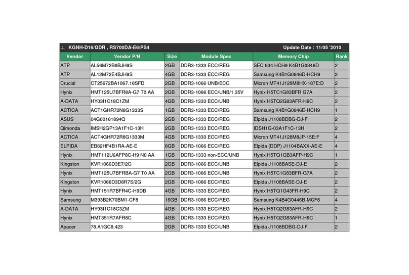
• The server has 12 DIMMs slots, six DIMM slots per processor, three DIMM slots
per channel.
• Up to 128GB, using PC3-8500R DDR3 Registered (RDIMM) memory, operating
at 800MHz when fully populated in 12 slots.
• Up to 32GB, using PC3-10600E DDR3 Unbuffered (UDIMM) memory, operating
at 1066MHz when fully populated at 2 DIMMs per channel in 12 slots.
• 4R (Quad-Rank) Registered (RDIMM) memory is supported in DIMM slots 2E
and 5F of both processors.
• Supported congurations:
o One DIMM per processor: 1A for CPU1; 1A for CPU2.
o Two DIMMs per processor: 1A, 4B for CPU1; 1A, 4B for CPU2.
o Four DIMMs per processor: 1A, 4B, 3C, 6D for CPU1; 1A, 4B, 3C, 6D
for CPU2;
oDIMM population order for processor socket 1: 1A, 4B, 3C, 6D, 2E, 5F.
o DIMM population order for processor socket 2: 1A, 4B, 3C, 6D, 2E, 5F.
Figure 6 DIMM slot population sequence
CAUTION: DIMMs can be damaged by improper handling. Always
use an anti-static wrist strap and grounding mat, and discharge static
electricity before touching DIMMs.
To install a memory module:
1. Align the notch on the bottom edge of the module with the keyed surface of the
DIMM slot and then press the module fully into the slot.
2. Firmly press the holding clips inward to secure the memory module in place.
Figure 7 Installing a memory module
DIMM slots are structured to ensure proper installation. If you insert a DIMM but
it does not t easily into the slot, you may have inserted it incorrectly. Reverse the
orientation of the DIMM and insert it again.
Installing a Processor
The server supports AMD 4100 Series Processors High Wattage 75W (6 Core and
4 Core), 50W (6 Core), and Low Wattage 32W (6 Core).
NOTE: If one processor is being installed, it should be installed in the socket closest
to the SR5690 chipset.
To install the processor:
1. Open the processor retaining latch and the processor socket retaining bracket.
Figure 8 Open the processor socket
IMPORTANT: Be sure the processor remains inside the processor
installation tool.
2. If the processor has separated from the installation tool, carefully reinsert the
processor in the tool.
Figure 9 Installing a processor in the installation tool
3. Align the processor installation tool with the socket and install the processor.
Figure 10 Installing a processor
4. Press down rmly until the processor installation tool clicks and separates from
the processor, and then remove the processor installation tool.
Figure 11 Removing the processor installation tool
5. Close the processor socket retaining bracket and the processor retaining latch.
Figure 12 Closing the processor socket
For processor removal, reverse the above installation procedures.
To install the heatsink:
CAUTION: Be sure that the heat sink sits squarely on the processor, or
overheating and damage to the processor may occur.
CAUTION: Heatsink screws should be tightened and loosened in opposite
sequence. Do not overtighten the screws as this can damage the system
board, connectors, or screws. A maximum torque of 6-8 in-lb is set for the
system.
1. Position the heatsink on the processor backplate.
2. Tighten the rst screw about three quarters in, then tighten the second screw
completely.
3. Completely tighten the rst screw.
Figure 13 Installing the heatsink
IMPORTANT: If the heat sink has been removed for any reason, it is
critical that you apply more thermal interface material to the integrated
heat spreader on the processor to ensure proper thermal bonding
between the processor and the heat sink. Clean the contact surface of
both the processor and heat sink with an alcohol pad, then re-apply an
HP-approved thermal interface material before reinstalling the processor.
Use a pattern of five dots when applying the thermal interface material—
one dot in the center, and one dot at each corner.
Additional Documentation
For additional documentation, refer to HP ProLiant SL335s G7 Server Documentation
CD. You can also access additional information and documentation from the HP
external website, either by connecting directly or through the Documentation CD.
Documentation Feedback
HP is committed to providing documentation that meets your needs. To help us improve
the documentation, send any errors, suggestions, or comments to Documentation
Feedback (mailto:docsfeedback@hp.com). Include the document title and part number,
version number, or the URL when submitting your feedback.