manuals.online logo
Brands
  1. Home
  2. •
  3. Brands
  4. •
  5. HPS
  6. •
  7. Water Filtration System
  8. •
  9. HPS TruWave Programming manual

HPS TruWave Programming manual

Disclaimer of Liability
The recommended practices in this manual are for general applications and are supplied without liability for errors or
omissions. Technical data are subject to change at any time without notice and any necessary corrections will be included
in subsequent editions.
Special requirements should be referenced back to the manufacturer and/or their representative.
Literature No.: AHFQS
Issue Date: June 2020
The pictures used in this guide are only a representation and may vary from the actual product.
HPS TruWave Active Harmonic Filter (AHF) Quick Start Instructions
These instructions will guide you through installing, testing your
installation, and starting up your AHF. For additional information
please refer to the owner manual provided with your AHF.
HPS TruWave Active Harmonic Filter Quick Start Instructions
2
Important Note:
Electrical equipment should be installed, operated,
serviced, and maintained, only by qualified personnel.
No responsibility is assumed by the manufacturer for any
consequences arising out of the use of this material.
WARNINGS
These instructions will guide you through installing, testing
your installation, and starting up your AHF. For additional
information please refer to the owner manual provided with
your AHF.
Installation of a AHF should only be performed by qualified
personnel.
Refer to the sections of the Owner’s Manual referenced
in the early steps of this procedure to install the AHF. The
safety precautions of Section 2 in the manual should be
read and understood prior to attempting an installation or
prior to opening a AHF enclosure any time after installation.
All wiring should meet the National Electric Code and any
applicable local standards.
The circuit from which the power leads to the AHF originate
should be off and locked out during installation.
The power source powering the wires monitored by the
external current transformers (CTs) should also be off and
locked out during installation of the CTs. Only after CTs are
properly terminated to the AHF (or to all AHFs in a paralleled
arrangement) should the power source powering the wires
monitored by the CTs be re-energized.
Do not open the output circuit of a current transformer
(CT) unless the circuit the CT monitoring is de-energized
or the CT has been physically removed from the circuit.
This includes not removing any connections from, or the
connectors themselves from P1 or P2 of the CT Interface
boards inside the AHFs. Opening the output circuit of a CT
could result in very high voltage that can cause the CT to
fail and represents an extremely dangerous condition to
personnel. Exception: If CTs are first connected to a shorting
terminal block prior to being wired to a AHF, and shorts are
applied across each CT’s pair of output wires on that block,
then CT related wiring continuing from the block to the
AHF may be opened without harm.
1. Read Section 1 in the manual to familiarize yourself
with how the AHF filters harmonic currents and power
saving features of the HPS AHF.
2. Read Section 2 in the manual to see the safety
precautions to follow when working on a AHF.
3. Section 3 in the manual covers the installation of the
system. Within this section, subsection 3.2 covers the
installation of a NEMA1 enclosed unit and subsection
3.3 covers the installation of a panel within a site-
specified enclosure, such as an MCC cabinet.
4. Subsection 3.4 covers how to wire a AHF. All systems
will need 3-phase power brought into the unit. Also,
either 2 or 3 Current transformers (CTs) are needed
to externally monitor either the “Line” side current or
“Load” side current. Examples are shown below.
Refer to section 3.4 of the manual if CT wires need to
be lengthened or for additional wiring arrangements,
especially arrangements that use paralleled AHFs.
You may use these Quick Start Instructions for a
paralleled system; however, you will need to also read
subsection 3.4.3 in the manual for wiring instructions.
Each system in the paralleled arrangement should be
checked individually with the other AHF(s) powered off.
An example of a “Line” side wired installation follows:
“Line” Side CT Installation
AHFQS / June 2020
3
An example of a “Load” side wired installation follows:
“Load” Side CT Installation
It is important to note that the CTs are in the correct
direction and on the correct phases. The direction of
the arrows on the CTs should agree with the direction of
the arrows in the previous Installation drawings. If using
CTs supplied from HPS, the output wires of the CTs are
black and white twisted wires, and must be wired to
the CT Interface Board inside the AHF as shown.
The phase “A” CT must be on the same phase that is
connected to the left terminal of the AHF’s power switch
(of a NEMA1 enclosed unit) or left power fuse block (of
a panel unit). The phase “B” CT must be on the same
phase that is connected to the middle terminal of the
power switch or middle power fuse block. The phase
“C” CT, if used, must be on the remaining phase.
ATTENTION: When using two CTs, always wire
to terminals A and B of connector P1 on the CT
Interface Board. The C terminal is only to be used
if a third CT is utilized.
The designation of phase A, B, and C is arbitrary, and
phase rotation does not affect the AHF.
5. If status feedback relays are desired to be monitored
by external hardware and/or the unit is to be externally
disabled by external hardware, subsection 3.5 covers
wiring to these optional features within the AHF.
6. Your AHF has the capability to automatically determine
if your CTs are placed on the correct phases and in the
correct direction. However, to do so, there must be
some load operating. This load cannot be too inductive
or capacitive in nature – one or more AC motor drives
operating at 20% or greater than the capacity of the
active filter is an excellent load. At this point a load
would need to be turned on before you proceed.
7. Once your AHF is correctly installed and wired, the unit
can be powered on. The unit will arrive from the factory
in the “disabled” state. This means that the controls
will power up, but the internal power circuitry will not
yet operate.
8. When power is applied to the system by turning on the
power switch, you should observe the following power-
up “splash” display:
If you get the full display, you may either wait 5 seconds
until the display changes to the “OPERATING STATUS”
display or press the “STOP” button on the display to
go to the “OPERATING STATUS” display immediately.
DO NOT press the “RUN” button on the display at this
time. If the display does not show anything, check to
make sure 3-phase going to the AHF, or if is different
than what is indicated above, contact the factory.
9. Once in the “OPERATING STATUS” display, press the
“MENU” button to display the main menu on the LCD
display:
10. The boxes around the words indicate that those items are
buttons that can be pressed to activate that function.
On the MENU display, press the “CT SETUP” button to
go to the current transformer (CT) setup display. For
more detailed information on the CT SETUP display,
refer to section 4 in the manual.
HPS TruWave Active Harmonic Filter Quick Start Instructions
4
As stated before, your AHF has the capability to
automatically determine if your CTs are placed on the
correct phases and in the correct direction. However,
to do so, there must be some load operating. This load
cannot be too inductive or capacitive in nature – one
or more AC motor drives operating at 20% or greater
than the capacity of the active filter is an excellent load.
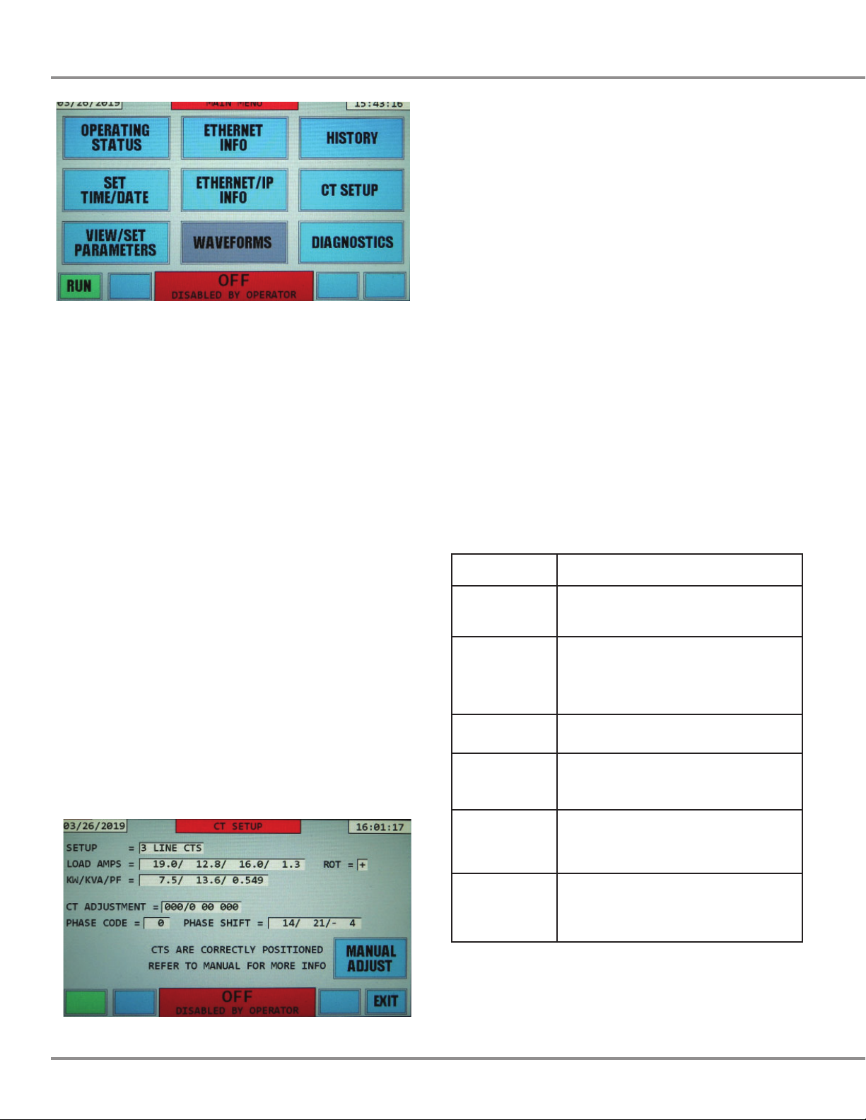
The first number in the 6th line is the “Phase code”.
This value will be “0” if your CTs are installed correctly.
A non-zero code between -28 and 43 indicates the CTs
are not on the correct phases and/or are in the wrong
direction. At this point if you see a value other than zero
you will need to refer to section 4 in the manual, tables
4.2 or 4.3.
If the message on the 7th line is “CTS ARE CORRECTLY
POSITIONED” or “CTS ARE CORRECTLY ADJUSTED”,
your CTs are on the correct phases for proper operation
and you can proceed to the next step.
If you observe any of the other messages in the following
table, refer to Table 4.1 of the manual for information on
how to correct the situation, and specifically go to the
subsection of section 4 shown in the following table for
the particular CT SETUP message displayed.
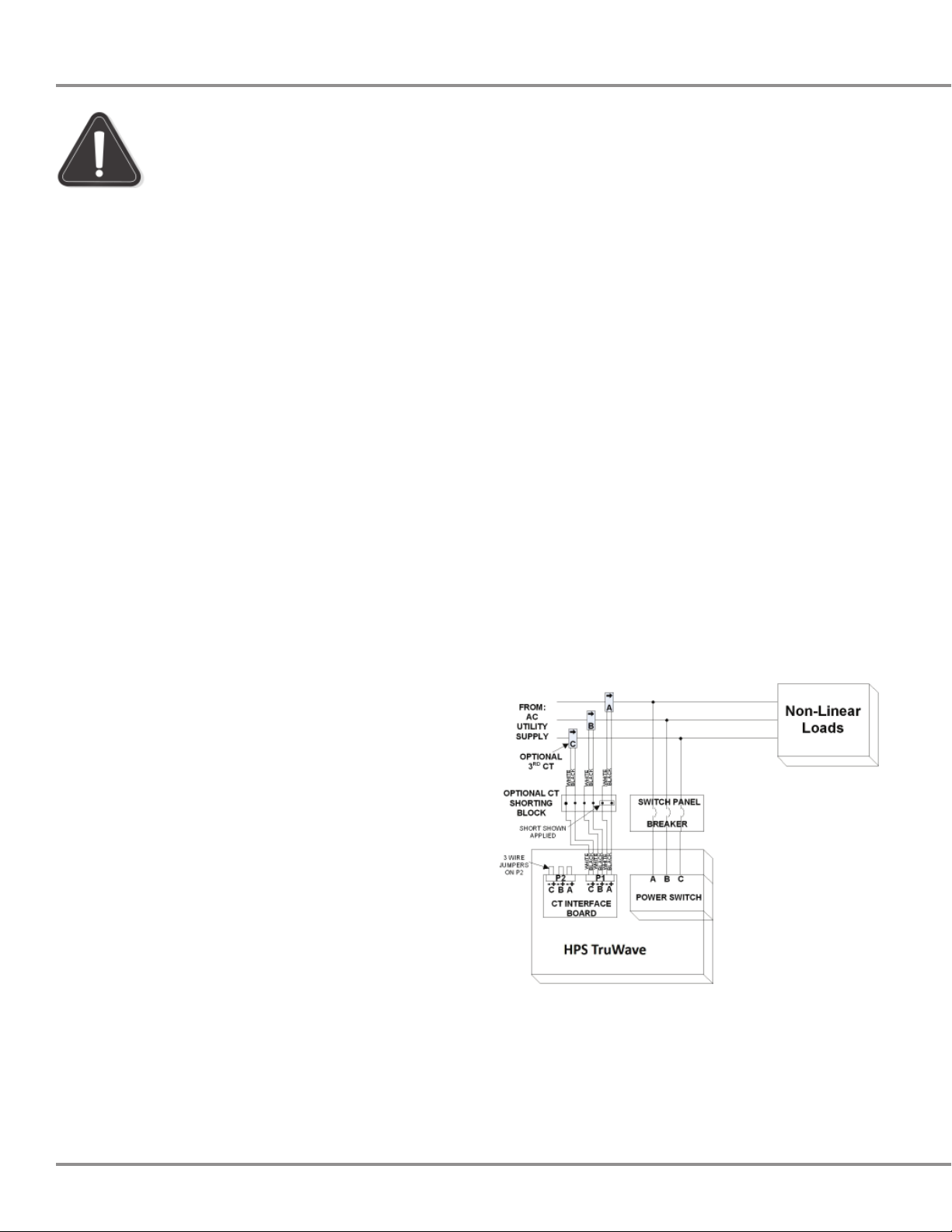
11. On the CT SETUP display, the 2nd line indicates how
many CTs the system is programmed for (2 or 3), and
whether the system is programmed for LINE or LOAD
side CTs. Verify that the number of CTs indicated and
the position (LINE or LOAD) agrees with the number of
physical CTs and location of those CTs you have wired
into your system. If not, you will need to either correct
your physical wiring to match the AHF configuration
shown, or change the AHF setup parameters. To
change these parameters, press the “MENU” button
on the display, followed by pressing the “VIEW/SET
PARAMETERS” button on the MENU display. Then refer
to sections 5.6, 5.6.2, and 5.6.7 to change the number
of CTs and/or position (Line or Load) of those CTs.
The 3rd line shows how much current is presently being
drawn by the load. The first 3 numbers, separated
by “/” characters are the 3 phases A, B, and C. The
4th number indicates the neutral current.The neutral
current is calculated by the AHF only for systems that
have 3 CTs.
The 4th line shows the present real power in KW and
apparent power in KVA, as well as the power factor of
the load.
The 5th line titled “CT ADJUSTMENT” indicates any
“programmed” adjustment that the AHF has been
set up for to compensate for CTs that are not placed
correctly.
CT SETUP
Message Explanation and Action to Take
LOAD CURRENT
TOO LOW
Insufficient load current to determine if
CTs are placed correctly. Go to subsection
4.1 in the owners’ manual to correct.
LOAD TOO
CAPACITIVE/
INDUCTIVE
Load current is high enough; however,
load is either too capacitive or inductive
to correctly determine if CTs are placed
correctly. Go to subsection 4.1 in the
owners’ manual to correct.
ERRONEOUS
PHASE CODE
Should not see this message. Stop and
contact factory if you do see it.
2 CTS ON A&C.
MUST BE ON A&B
When using 2 CTs, they must be located
on phases A and B. Go to subsection 4.2
in the owners’ manual to correct.
2 CTS ON B&C.
MUST BE ON A&B
When using 2 CTs, they must be located
on phases A and B. Go to subsection 4.2
in the owners’ manual to correct.
FIX CTS OR
ADJUST HERE
CTs are not on the correct phases and/
or are in the wrong direction. Go to
subsection 4.2 in the owners’ manual to
correct.
Your AHF also has the capability to automatically correct
for certain incorrect CT placements, without rewiring or
moving CTs. Refer to section 4.2.3. of the manual in order
to use this feature.
AHFQS / June 2020
5
12. If the message “CTS ARE CORRECTLY POSITIONED”
or “CTS ARE CORRECTLY ADJUSTED” is shown
on the CT SETUP display, it is now time to enable
the AHF to start correcting harmonics. Exit the CT
SETUP display by pressing the MENU button in the
bottom right corner of the display. Then press the
OPERATING STATUS button on the MENU display to
bring up the OPERATING STATUS display:
13. To enable the system, press the “RUN” button in
the bottom left corner of the OPERATING STATUS
LCD display page. This will result in the following
display: This screen allows the operator to confirm
the “RUN” command, or exit without enabling
the system in case the “RUN” button was pressed
accidentally. Pressing the “EXIT” button will bring
up the previous display page without enabling the
system. If the “RUN” button is not pressed within
10 seconds, the effect will be the same as pressing
the “EXIT” button. If the “RUN” button is pressed
within 10 seconds, the AHF system will be enabled
and begin to operate.
14. The AHF will begin charging the internal DC bus,
which takes 1 to 10 seconds depending on AHF size.
This is indicated by a “PRECHARGING” message on
the display. The pre-charging voltage and current are
displayed at the bottom of the screen. This can be
seen in the sample screen that follows.
Note that once the AHF is told to RUN, the place where
the RUN button was previously located, is now a STOP
button.
15. When the DC voltage bus has been completely
pre-charged and the control determines it is OK to
proceed, the AHF begins correcting the harmonics and
power factor of the line, and the display will indicate
that the unit is operating. This is indicated by the
“ON”/“FULLY OPERATIONAL” or “ON”/“REDUCED
LINEAR PF MODE” status.
If the system is working correctly, the LOAD THDR%
(total harmonic current distortion of the current fed
to the loads) will still be relatively high (66.9% in this
example); however, the LINE THDR% (total harmonic
current distortion of the current drawn from the line)
will be low (3.9% in this example). For most loads and
line conditions, as long as the AHF is loaded to at least
25% (98.5% in this 100 Amp AHF example as seen
in the AHF % LOADED line), you should be able to
achieve less than 5% THDR% on the LINE. The load
requiring more harmonic current correction than the
unit can deliver, very high THDR loads, highly distorted
line voltage, or high impedance in the line feeds could
result in a higher THDR% from the line.
If substantially lower THDR% is not observed in the
LINE THDR% displayed compared with the LOAD
THDR% and the AHF is loaded to at least 10%, you
probably have an installation problem. Disable the AHF
by pressing the STOP button. When the next display
asks you to confirm the STOP command, press the
HPS TruWave Active Harmonic Filter Quick Start Instructions
6
STOP button on that display as well.
If the unit detects that it is not correcting harmonics
satisfactorily, it may shut itself down. It will then
attempt to reset (indicated by the splash screen being
displayed). It could perform this cycle a few times before
“giving up”. If it reaches this point, the OPERATING
STATUS display will indicate a status of OFF and the
reason for the problem underneath this OFF status.
Even if your CTs are placed on the correct lines and
in the correct direction, if you have them placed on
the LOAD side, but have told the AHF they are on the
LINE side, or vice-versa, the system will not operate
correctly. This is the most likely reason for your AHF to
not be operating correctly at this time. Recheck your
CT locations. If all CTs and settings seem to be correct,
consult the factory for additional assistance.
16. Once you have confirmed that your CTs are correctly
placed, and the unit is operating properly, the AHF
should give you years of trouble-free, harmonic-
correcting operation, requiring minimal maintenance.
To insure a long life for your unit, regularly inspect the
air filter(s) on the front and/or bottom of the unit and
clean or change when dirty.
For Parallel AHF Installation Only:
After each AHF has been tested, they may now be
powered and enabled to run. Once running, the THDR%
of the line should again be substantially lower than the
THDR% of the load for all AHFs in the paralleled setup.
It should be noted that actual THDR% of the line will
only be equal to the line THDR% shown on any of the
paralleled AHFs if all AHFs are operating and %LOAD
values (see subsection 3.4.3 of the manual) for all
paralleled operating AHFs add up to 100%.

Popular Water Filtration System manuals by other brands

STA-RITE PRC50 owner's manual

STA-RITE

STA-RITE PRC50 owner's manual

AquaticLife 540565 Installation, operation, maintenance guide

AquaticLife

AquaticLife 540565 Installation, operation, maintenance guide

Sunshine Pool Products SPE installation instructions

Sunshine Pool Products

Sunshine Pool Products SPE installation instructions

Exo Terra Turtle Filter PT3630 operating instructions

Exo Terra

Exo Terra Turtle Filter PT3630 operating instructions

Vertex Puratek Installation and maintenance manual

Vertex

Vertex Puratek Installation and maintenance manual

brondell UC 300 installation guide

brondell

brondell UC 300 installation guide

AquaSure FORTITUDE V Series owner's manual

AquaSure

AquaSure FORTITUDE V Series owner's manual

BWT Infinity A+AP Installation and operating manual

BWT

BWT Infinity A+AP Installation and operating manual

Watts Hydro-Safe Cold Bev Max-S2 Installation, operation and maintenance manual

Watts

Watts Hydro-Safe Cold Bev Max-S2 Installation, operation and maintenance manual

Graco 287995 instructions

Graco

Graco 287995 instructions

WilTec 52367 user manual

WilTec

WilTec 52367 user manual

Unilever Pureit PX3000 instruction manual

Unilever

Unilever Pureit PX3000 instruction manual

flamco MeiFlow Shunt UD DN15 S Installation & service instructions

flamco

flamco MeiFlow Shunt UD DN15 S Installation & service instructions

Vents FB 100 user manual

Vents

Vents FB 100 user manual

FreshWater SH-CQ/3 Installation guide & technical information

FreshWater

FreshWater SH-CQ/3 Installation guide & technical information

T.I.P. MTS 6000 UV 7 operating instructions

T.I.P.

T.I.P. MTS 6000 UV 7 operating instructions

Fuji Electric ecoWAVE Econ-Line PHF Series Installation & user manual

Fuji Electric

Fuji Electric ecoWAVE Econ-Line PHF Series Installation & user manual

Giebel VG-R 1L Assembly and maintenance instructions

Giebel

Giebel VG-R 1L Assembly and maintenance instructions

manuals.online logo
manuals.online logoBrands
  • About & Mission
  • Contact us
  • Privacy Policy
  • Terms and Conditions

Copyright 2025 Manuals.Online. All Rights Reserved.