HPtec SD4030B User manual

SD4030B-M0 8
取扱説明書
Operating Manual
2相ステッピングモータ用 For 2 Phase Stepping Motor
バイポーラマイクロステップドライバ Bipolar Micro Step Drive r
LOW COST
3 Amax /相 phase
電源40 Vmax Supply Voltage
低振動 Low Vibration
SD4030B

SD4030B-M0 8
― はじめに ― Before Operating
このたびは SD4030B をお買い求め頂きましてまことにありがとうございます。本書は SD4030B の仕様、
使用方法について説明しています。 SD4030B をご利用になる前には必ず本書を熟読の上、正しくお使い下
さい。
Thank you for purchasing the HI-P Tec products. This manual describes on the specification and the usage.
Please review the material in this manual thoroughly before using SD4030B.
― 保証について ― After Sales Service(Repair)
● 納入後1年以内にユーザー殿での取り扱い方法に誤りがなく故障した場合は無償交換致します。
When the product is incorporate to the machine inspire of your correct usage within a year, we will
replace it by new product in free of charge.
― 使用上のご注意 ― Cautions for Proper Use
● 定格および使用環境を守ってお使いください。
Please use under the absolute maximum ratings and the environmental.
● 弊社製品は、人命にかかわるような状況下で使用される機器に用いられることを目的として設計,製造された
ものではありません。 特殊用途での使用をご検討の際には、弊社営業窓口までご照会ください。
This product is intended to be used with a general industries products, but nor designed or manufactured
to be used in a machine or system that may cause personal death when it is failed.
Consult us if the application of this product is under such special conditions and environments.
● 弊社では、品質,信頼性の向上に努めておりますが、システム設計の際には故障による、人身事故,火災事
故,社会的な損害を生じさせないための冗長設計,延焼対策設計,誤動作防止設計等、安全設計に十分ご注意
下さい。
We have been making the best effort to ensure the highest quality of the products, however, it is highly
recommended that you make a redundant design, Anti-fire design, secure the safety in the operative range
and fail-safe design in order to avoid damage or loss of social.
● 本製品は今後特性改良等のため、予告なく仕様を変更する場合があります。
Contents of this manual are subject to change without prior notice for functional improvement, change of
Specifications or user's better understanding..

SD4030B
― 安全上のご注意 ― Safety Precautions
本書では、 SD4030B を安全に使用していただくために、注意事項を次のような表示で示しています。ここで示し
た注意事項は、安全に関する重大な内容を記載しています。必ず守って下さい。
Various icons and important messages are used in this manual to avoid problems that could result in hazards
to personnel and damage to properties.. Please observe the contents.
取り扱いを誤った場合に 、 危険な状況が起こりえて 、 人が死亡または重症を受ける
可能性が想定される内容を表示します。
Danger Danger statements are used to indicate hazardous unsafe practices witch COULD
result in severe personal injury or death.
取り扱いを誤った場合に 、 危険な状況が起こりえて 、 人が中程度の障害や軽傷を受
ける可能性が想定される場合 。 および物的損害の発生が想定される内容を表示しま
す。
Caution Caution statements are used to indicate hazards or unsafe practices which COULD
result in minor personal injury or product or property damage.
してはならない内容を表示します。
This symbol is used to indicate a practice that shall not be attempted.
しなければならない内容を表示します。
This symbol is used to indicate a practice that shall be done.
●通電中は、端子部および内部には絶対に手を触れないで下さい。感電の恐れがあります。
Never touch any terminals and internal in active. Could cause electric shock.
●ケーブルは 、 無理に引っ張ったり曲げたり 、 重いものを載せないで下さい 。 感電 、 火災の恐れがありま
す。
Don't damage leadwires or subject leadwires to excessive stress such as strong pressure, heavy
object and clamping load.. Could cause electric shock..
●可動部を絶対に手で触れないでください。ロータに巻き込まれてケガをする恐れがあります
Never touch part of rotating, parts,. Could cause personal injury by involved to the rotor.
●駆動中モータ表面又はパワー素子が異常に熱くなることがありますので火傷の恐れがあります
Don't touch potentially hot motor casing, it will cause burn injury.
! 危険
! 注意
禁止
! 危険
!強制

SD4030B
●水、油、薬品などの飛沫がかかる場所、腐食性ガス、可燃性ガスのある場所では使用しないで下さい 。
Don't use at where splashed with water, oil, chemicals and at where corrosive environment or flammable
gas.
●定格の電源電圧で使用して下さい。火災の恐れがあります。
Please use the rated voltage. Could cause a fire.
●実装部品は 、 通電中や電源遮断後しばらくの間は 、 温度が高くなりますので触れないで下さい 。 やけど
の恐れがあります。
During power distribution and while after power loss, don't touch any electric parts due to such high
temperature to burn.
●配線は正しく確実に行って下さい。
Wiring work should be done by a qualified electrician.
●直射日光のあたる場所では使用、または保管しないで下さい。
Don't use and keep in a place of direct sunshine where..
●周囲温度や相対湿度が仕様の範囲を超えるような場所では使用、または保管しないで下さい。
Don't use and keep in a place of such where may be beyond the range of ambient temperature and
relative humidity specifications.
●塵、埃などの多い場所では使用、または保管しないで下さい。
Don't use and keep in a place of dust, dirt and a lot of.
●直接振動や衝撃が伝わる場所では使用、または保管しないで下さい。
Don't use and keep in a place subject to excessive vibration or shock..
●修理や改造はしないでください。
Never attempt to perform repair and modification by yourself.
●即時に動作を停止しできるように外部に非常停止回路を設置してください。
Connect a emergency stop circuit to turn off upon being emergency case.
! 注意
禁止
!強制

SD4030B-M0 8
------------------- 目 次 Table of Contents ---------------------
1. 注意事項(ご使用される前に必ずお読みください)
Precautions : Please review this manual thoroughly before using the product.
····································
1
1-1 設置について Installation
······················································································································
1
1-2 電源電圧について Supply Voltage
·······································································································
1
1-3 コネクタの接続について Connectors
···································································································
1
1-4 分割について Micro-step Resolution
·····································································································
1
1-5 モータの発熱について Motor Heating
··································································································
1
1-6 マイクロステップの電流値について Micro-step Current
····································································
1
1-7 ユニポーラタイプのモータ駆動について Operatiing Unipolar Motor
···················································
1
2. 主な仕様 Specifications
····························································································································
2
3. コネクタピンアサイン Connector pin assignment
·······················································································
3
3-1 CN1
··························································································································································
3
3- 2 CN2
··························································································································································
3
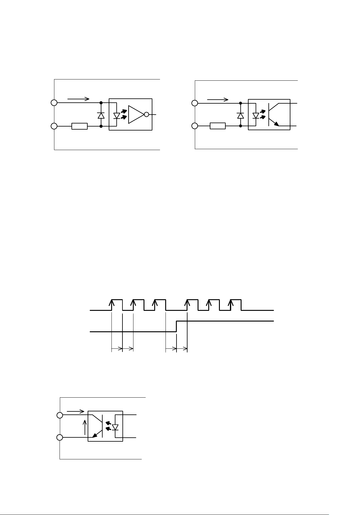
4. 入出力回路図 Input/Output schematic
····································································································
3
5. モータの接続方法 Connection Diagram to Motor
···················································································
5
5-1 バイポーラタイプのモータの場合 Bipolar Connetion
···········································································
5
5-2 ユニポーラタイプのモータの場合 Unipolar Connection
·······································································
5
6. スイッチ(SW1)の設定 Swtich Setting
·································································································
6
7. POW LED
··················································································································································
7
8. ミックスディケイについて Mix Decay Operation (Vibration Suppression)
················································
7
9. JOG動作 JOG Operation
··························································································································
7
10. ボリュームの設定 Volume Setting
·········································································································
7
10-1 RUNボリューム RUN Volume
·············································································································
7
10-2 STOP ボリューム STOP Volume
·········································································································
8
10-3 JOGボリューム JOG Bolume
···············································································································
8
11. RUNボリュームの正確な調整方法 Correct Adjustment for RUN Volume
·········································
9
12. 電源電圧による出力電流の減定格について Output current depend on Supply Voltage
·················
9
13. 部品配置図 Componets Layout
·········································································································
10
14. 外形寸法図 Dimension
·························································································································
10

SD4030B
1
1. 注意事項( ご使用される前に必ずお読みください )
Caution : Please read following contents before using the product.
設置について Installation
本ドライバは取り付ける方向は2通りの選択できますが以下の設置方法を厳守してください
This driver can be set in two kinds of direction but obey to following setup method.
•
•
•
•ドライバの周辺は空気の対流があり周囲温度が 周辺5cm以内定格温度(40 ℃ 以下) の場所に設置
設してください
Setup a driver at atmosphere well-ventilated and within ranged temperature (less than 40degree)
in ambient temperature at around 5cm..
•
•
•
•複数軸ご使用の場合は各ドライバ間 10mm 以上の空間を空けてください
Using for multi-axis, keep space more than 10 m m space among the driver..
•
•
•
•ドライバは筐体放熱を前提としております。特に2 A 以上で連続でご使用される場合必ずシャーシを
筐体にネジで固定してご使用ください。設置されてから十分なエージング動作を行いドライバのシャーシ
温度が50 ℃ 以下になることをご確認ください。
もしそれ以上の温度になる場合はカレントダウンを併用して電流値を下げるか又はファンモータ等で
強制空冷を行ってください。
As being condition of using the driver on cooling body, especially impale the chassis with screws in
case of using at more than 2A continuously. After setup, implement much aging work, and make sure
that the body temperature is less than 50degree.
When becoming any more temperature, it uses current down and lower a current value or do forced air
cooling with the fan motor and so on.
1-1 電源電圧について Supply Voltage
電源電圧が24 V を超えてモータを連続回転でご使用される場合は出力ピーク電流値が減定格となり
ます。 11 ページのグラフに従って電流値を絞ってご使用ください。
If power supply being over 24V continuously, Narrow down a current value according to the graph of
page 11 and use i t because Peak current of output become the rated current of output become
decreasing..
コネクタの接続について Connector
特に電源の配線には充分注意してください。本ドライバは電源の極性を間違えても壊れない回路構成に
なっていますが、モータ出力端子に電源を配線するとドライバが 破損 し ます。
ケーブルは 4 ページに記載された線材及びむきしろの長さを守ってください。又端子台ねじの締め付け
は0. 22~0.24N.m のトルクで締め付けてください。これによりねじのゆるみ、電線の抜けを防止で
き ます。
Especially, be careful of the wiring by the power sufficiently . I n the circuit composition which doesn't
break even if this driver makes a mistake in the polarity of the power .
The wire rods which were mentioned to page 4 and the cable keep uncoated length of wire turning.
Also, fasten up the fastening-up of a terminal block screw at the torque of 0.22-0.24N.m.
The pulling-out of the looseness, the wire of the screw can be prevented by this.

SD4030B
2
1-2 分割について Micro-step Resolution
マイクロステップの分割はステッピングモータの A 相と B 相それぞれの電流を電気的に近似正弦波に
よりベクトル分割しているため、分割された1ステップ角がそのまま機械的位置精度を保証するものでは
ありません。機械的位置精度はモータ自信の機械精度及び駆動される装置の機械精度に依存します。
Micro-stepping is split into A and B phase sine wave current in each electrical phase since splitting from
the vector . T he positional accuracy is not guaranteed as it is a mechanical step angle is divided
Mechanical positioning accuracy depends on the accuracy and precision mechanical devices driven by
the motor machinery of confidence.
モータの発熱について Motor Heating
駆動中モータの表面が非常に熱くなりますので 火傷 には充分ご注意下さい。
モータの表面温度が 100 ℃ を超える 場合はモータを 損傷する 可能性がありますので “ RUN ” ボリューム
で電流値を下げるか、強制空冷によりモータを冷却して100 ℃ を超えないようにして下さい。
又自動カレントダウンを有効にして停止中の電流を下げることも発熱防止となります。
Since the surface temperature of motor becomes high during operation, take care not to burn injury.
In case of the surface temperature of motor exceeding 100 degrees C, it is possible to damage the
motor. So Operate not to exceed 100 degrees C by dropping the current by RUN volume or forced
cooling. Then enable of auto current down function become prevent heating due to decreasing current
under suspension.
1-3 マイクロステップの電流値について Micro step current
“ RUN ” ボリュームによる設定電流値は近似正弦波電流の波高値となります。
Configuration current by RUN VOLUME equal to peak current of approximate sine wave.
1-4 ユニポーラタイプのモータ駆動について Operating Unipolar Operating.
本ドライバはバイポーラタイプのモータ用ですがユニポーラタイプのモータも駆動できます。
結線方法については取説の 6 ページを参照してください。
This driver is for the bipolar -type motor but can drive the motor of unipolar-type, too.
Refer to the page 6 of th is operation manual therefore in the connection method.
2. 主な仕様 Specifications
Specifications
Specifications
Specifications
項 目 Item 内 容 Description 備 考 Note
型 式
Model name
SD4030 B
入力電源電圧
Input Voltagee
+18V~40V
適合モータ
Applicable Motor
2相ステッピングモータ(バイポーラタイプ)
2 Phase Step Motor( Bipolar type)
ユニポーラタイプも駆動可
Available for Unipolar oepration
出力電流
Output Current
0.5~3A peak ( ± 5%)/相 Phase
電源24 V を超える場合は減定
格となります
Being lower rated output current
beyond Power Supply 24V

SD4030B
3
駆動方式
Drive Method
バイポーラ定電流チョッパー方式
Chopper mode by Bipolar constant current
カレントダウン機能
Current Down function
自動カレントダウン
パルス停止後約0.7秒で電流を CDN ボリュ
ームで設定された電流に下げる
Auto Current down
Adjusting to set lower current of CND
volume after 0.7 second after pullse stop
スイッチにより機能選択可能
Selectable by switch.
最大入力パルス周波数
Maximum Input Pulse
Cycle
100Kpps
調整機能
Adjusting
RUN 励磁電流設定用(0.5~3 A )
For Coil current
出荷時は2 A に設定される
The default factory setting is 2A.
STOP カレントダウン時の電流設定用
For current value on current down mode.
RUN 電流の10%~60%
Selectable between 10% to 60%
of RUN current.
JOG JOG の速度設定用
For JOG speed.
30 0pps ~ 1 4Kpps
選択機能
Select
Function
SW-1,2,3 分割数選択
Select of Resolutions
1/2,1/8,1/10,1/16,1/20
1/32,1/40,1/64
SW-4 自動カレントダウン有効/無効選択
ON/OFF for function of auto current down
mode..
スイッチO N で有効 , O FF で無効
出荷時は “ 有効 ” に設定される
Switch ON is condition and OFF
is no condition. The default
factory setting is ON..
SW-5,6 ミックスディケイ比率選択
Mixed Decay ratio
75%,50%,25%、5%
SW-7,8 JOG 機能選択
Select of JOG function.
SW-7 ON で JOG 有効
SW-8 ON で CW 、 OFF で CCW
入力信号
Input
Signals
P+,P- 指令パルス Pulse Command
フォトカプラで絶縁
Photo IsolationD+,D- 指令方向 Direction Command
O F F +,OFF- 励磁 OFF Motor Stop
出力信号
Output
Signals
ALM+,ALM- アラーム(パワー素子過熱検出)
パワー素子内の温度が 170 ℃ ( Typ .)に
達したときに出力
Alarm (Prospecting of over-heat for Power
device)
フォトカプラで絶縁
正常時 ON 、アラーム時 OFF
Photo Isolation
ON is conditions, OFF is no
conditions(ALARM).
外形寸法
Di m ension
外形W90 × D55.5 × H28

SD4030B
4
重量
Weight
106g
動作温度・湿度
Operating Temperature
and Humidity
0~40 ℃ 、35~80% 結露なきこと
No condensation
保存温度・湿度
Storage Temperature
and Humidity
-20~+85 ℃ 、35~80% 結露なきこと
No condensation
3. コネクタピンアサイン Connector
Connector
Connector
Connector pin
pin
pin
pin assignment
assignment
assignment
assignment
3-1
CN1
No. 信 号 名 内 容 IN/OUT
6 /B モータ/B相 OUT
5 B モータB相 OUT
4 /A モータ/A相 OUT
3 A モータA相 OUT
2 0V 電源0V入力 IN
1 +V 電源プラス入力(18V~40V) IN
適合端子台 : MC1.5/6-ST-3.5 (フェニックスコンタクト)
Recommendation: MC1.5/6-ST-3.5 (by Phoenix Contact)
3-2 CN2
No. 信 号 名 内 容 IN/OUT
8 AL M - パワー素子過熱アラーム
(アラーム時OFF)
OUT
OUT7 A LM +
6 OFF- 励磁オフ入力
(入力抵抗220 Ω )
IN
IN5 OFF+
4 D- 指令方向入力
(入力抵抗220 Ω )
IN
IN3 D+
2 P-
指令パルス入力
(入力抵抗220 Ω )
IN
IN1 P+
適合端子台 : MC1.5/8-ST-3.5 (フェニックスコンタクト)
Terminal confirmance MC1.5/6-ST-3.5 (by Phoenix Contact)
注意1)電源とモータの配線は特にピン番号を間違えないよう十分注意してください
注意2)使用電線サイズ:AWG28~AWG16 ( より線 )
Note 1) Especially take extra care pin number not to mix up Power line for Motor line.
Note 2) Usable specification of Power line is AWG28 to AWG16 with twisted pair line.
電線むき長さ: 6 ~7mm
6 ~ 7mm
先端を予備半田しないこと! Not for pre-soldering
(正しい接続ができなくなります)

SD4030B
5
2 2 0 Ω
+
-
1 0 m A ≦ I
L
≦ 1 6 m A
T L P 1 1 4 A
又は相当品
I
L
t 1 t 2
t 3 t 4
P -
D -
C W
C C W
t 1 , t 2 , t 3 , t 4 ≧ 5 μ s e c
4
4
4
4入出力回路図 Input/Output
Input/Output
Input/Output
Input/Output schematic
schematic
schematic
schematic
指令パルス(P)、指令方向(D) 励磁オフ(OFF)
Pulse Command(P), Direction Command(D) Excitation OFF
注意)ラインドライバで駆動される場合、上記の最小入力電流10m A を満足することができなくなる可能性
があります。その際はプラス側を+5 V に接続し、ラインドライバの片側をマイナス側に入力して
ご使用ください。
Note) Operating with line drive component, there is a possibility that minimum input current is lower than
10mA, then wire plus pin of line drive input to 5V and the another pin to minus.
�指令入力パルスの論理について Theme of Input pulse for command
指令パルスは内部フォトカプラ出力のアップエッジでカウントされます。指令方向はモータが通常の結線の
場合内部フォトカプラ出力が “ LOW ”のと き CW 、 ” HIGH “ のと き CC W に回転します。フォトカプラは1次 側 LE D
が ON で出力が LOW となります。なおモータの回転方向は結線によっても変わりますのでご注意ください。
下図にタイムチャートを示します
Pulse command acknowledge s the rising edge of internal photo coupler output. For Direction command,
motor rotation direction depends on output level of photo coupler, CW on Low and CCW on High.
アラーム出力(ALM) Alarm Output
T L P 2 8 1 G B ( 東 芝 )
又は相当品
I
L
5 m A ≦ I
L
≦ 3 0 m A
2 2 0 Ω
+
-
T L P 2 8 1 G B ( 東 芝 )
又は相当品
+
-
V C E
I o
I o ≦ 4 m A
V C E ≦ 5 0 V m a x

SD4030B
6
5
5
5
5モータの接続方法 Connection
Connection
Connection
Connection Diagram
Diagram
Diagram
Diagram to
to
to
to motor
motor
motor
motor
5-1 バイポーラタイプのモータの場合 Bipolar Connection
5-2 ユニポーラタイプのモータの場合 Unipolar Connection
結線方法1:ユニポーラのマイクロステップドライバと同じ電流設定でトルクとモータの発熱がほぼ同じとなり
ます。通常はこちらの結成方法を使用してください。
Connection method 1: That a torque and a motor are heated becomes the same approximately with the
electric current setting which is the same as the micro-step driver of unipolar.
To be general use a way of this connection method .
結線方法2:高トルクで且つ低速で使用されたいときに有効となります。モータの発熱を結線方法1と等価に
するためには最大電流を70%に絞ってご使用ください。その際低速域のトルクは1.4倍となりますが、
コイルのインダクタンスが結線方法1と比べ4倍となりますので回転数の上昇に対するトルクの落ち込みが
大きくなります。
Connection method 2: It becomes effective when wanting to be used at low speed in the high torque.
To make that a motor is heated equivalent to connection method 1, narrow down a maximum electric
current to 70 % and use it.
The falling of the torque to the rise of the number of rotations becomes big because the torque of the case
low speed area gets for 1.4 but the inductance of the coil becomes quadruple compared with connection
method 1.
A
/ A
B
/ B
C N 1
A 相 コ イ ル
B 相 コ イ ル
ス テ ッ ヒ ゚ ン ク ゙ モ ー タ
/ A 相 コ イ ル
/ B 相 コ イ ル
ス テ ッ ヒ ゚ ン ク ゙ モ ー タ
A 相 コ イ ル
B 相 コ イ ル
C O M
C O M
A
/ A
B
/ B
C N 1
A 相 コ イ ル
B 相 コ イ ル
ス テ ッ ヒ ゚ ン ク ゙ モ ー タ
/ A 相 コ イ ル
/ B 相 コ イ ル
C O M
C O M
A
/ A
B
/ B
C N 1

SD4030B
7
4. スイッチ(SW1)の設定
Setting
Setting
Setting
Setting Switch(SW1)
Switch(SW1)
Switch(SW1)
Switch(SW1)
Note: It is necessary for setting 7 and 8 to OFF i n normal input pulse oerating. .
■ JOG動作の設定
OG Operation Setting
7 8 JOG回転
☆
ON ON CW
ON OFF CCW
OFF OFF JOG動作無効
注意)通常のパルス入力動作の時は
7と8を必ずOFFに設定してください
■ ミックスディケイの比率設定
fMixed Decay Ratio Setting
5 6 スローディケイ率
☆OFF OFF 75%
ON OFF 50%
OFF ON 25%
ON ON 5%
■ 自動カレントダウンの設定
Auto Current Down Setting
4
☆ON 有効
OFF 無効
■ 分割数の設定 Micro r esolution setting
1 2 3 分割数
ON ON ON 1/2
ON ON OFF 1/8
ON OFF ON 1/10
ON OFF OFF 1/16
OFF ON ON 1/20
OFF ON OFF 1/32
OFF OFF ON 1/40
OFF OFF OFF 1/64
☆

SD4030B
8
5. POW LED
電源が投入されると緑色に点灯します。電源を投入しても点灯しない場合は電源の極性が逆になっている
か、接続ミスによりパワーモジュールが壊れている可能性があります。
本ドライバは電源が逆に接続されても壊れない回路構成となっておりますので、正しい接続に直してから電
源を再投入してください。パワーモジュールが壊れている場合は本体交換となります。
LEDの場所については 11 ページ の部品配置図を参照してください。
I t lights up to the green when a power is invested. When not lighting up even if it turns on, there is possibility
that the polarity of the power becomes opposite or that the connection mistake breaks a power module.
Because this driver becomes the circuit composition which doesn't break even if a power is connected
oppositely, re- turn on after correcting to the right connection.
When a power module is broken, it becomes this unit exchange.
Refer to component layout which is page of 1 1 . therefore in the place of the LED.
6. ミックスディケイについて
Mix
Mix
Mix
Mix Decay
Decay
Decay
Decay
SW-1の5,6で電流の減衰カーブを調整することができます。
ミックスディケイ動作によりモータの振動を抑制することができます。下表に従いご使用のモータ及びご使用
の回転数でモータの振動が少なくなる設定にしてご使用ください。
The attenuation curve of the electric current can be adjusted at 5, 6 of SW-1.
The vibration of the motor can be restrained by the mixed decay operation.
The vibration of the motor make decreasing setting at the motor of the use according to the following table
and the number of rotations of the use and use.
スローディケイ率
Slow Decay Ratio
効果
The effect
75% 極低速で振動低減効果あり
Reduction in vibration at very slow speed.
50% 0. 5rps以上で振動低減効果あり
In the vibration reduction over 0.5rps.
25% 更に高速で振動低減効果あり
Further reduction in vibration at high speed.
5%
7. JOG動作 JOG
JOG
JOG
JOG operation
operation
operation
operation
SW1-7がONのときPUSHスイッチによるJOG動作が可能になります
JOG 動作を行う時はCN2を外して行ってください。
SW1-8で回転方向が選択できボリューム “ JOG ” でパルスの周波数が可変できます
JO G 動作はあくまでドライバとモータの試運転用に使用し、モータ単体で動作させてください。装置に組み込
んでからの使用は危険ですので行わないでください。
通常のパルス入力動作時はSW1-7と8を必ずOFFにしてください
When SW 1-7 turns ON, PUSH switch allows JOG operation
Working JOG operation go off CN2.
The direction of rotation can be selected by SW 1-8 and TRIMMER JOG adjustable pulse frequency.
JOG operation is used for test run for driver and motor end, and let alone operate a motor.

SD4030B
9
8. ボリュームの設定
Trimmer
Trimmer
Trimmer
Trimmer Setting
Setting
Setting
Setting
10-1 RUNボリューム RUN TRIMMER
運転時のピーク電流の設定用です。出荷時は2Aに設定されています。
Selectable peak current in operation , and the default factory shipment is 2A.
10-2 STOP ボリューム STOP TRIMMER
自動カレントダウン時の電流の設定用でRUNボリュームの設定に対する比率となります
For set of current value in auto current down mode and selectable the ratio(percentage) to peak
current "RUN TRIMMER".
10-3 JOGボリューム JOG TRIMMER
JOG動作時の周波数を設定します。下記周波数はあくまでも目安ですのでモータの回転数を見ながら
調整してください。又ボリュームの角度と周波数は直線的には変化しません。センター付近から急激に
立ち上がりますのでご注意ください
For set of the frequency during JOG operation. The following frequency is estimated only so looking at the
motor speed while adjustment. The angle and the frequency does not change linearity with the trimmer .
Therefor be much careful for rising up rapidly from part of center..
0.5 A
1.7 A
1.3A
2A
2.4A1A
0.75A
2.7 A
3A
“ RUN ” ボリューム
10%
45%
36%
48%
52%29%
22%
56%
60%
“ STOP ” ボリューム

SD4030B
10
10.
10.
10.
10. RUNボリュームの正確な調整方法 Correct
Correct
Correct
Correct adjustment
adjustment
adjustment
adjustment of
of
of
of RUN
RUN
RUN
RUN TRIMMER
TRIMMER
TRIMMER
TRIMMER
直流電流計を用意してください。電源を投入する前にコネクタCN1のA相に電流計のプラス側、モータのA
相に電流計のマイナス側を接続してください。ドライバのSW1 ― 4をOFFにしてください。
電源を投入しRUNボリュームで目的の電流値に調整してください。
・ Set up a DC ammeter.
・ Before power ON, connect plus pole of DC ammeter to A-phase of CN1 and minus pole to A-phase of
Motor.
・ Turn OFF SW1-4 of the driver.
・ After power ON, adjust to target current value with RUN"TRIMMER..
300pps
14Kpps
630pps
“ JOG ” ボリューム
2相
ステッピング
モータ
電源+
電源0V
+V
0V
A相A相
/A相
B相
/B相
CN1
直流電流計
DC
+-
/B相
B相
/A相
Power Supply
DC Ammeter
Motor
Driver

SD4030B
11
9. 電源電圧による出力電流の減定格について
Output
Output
Output
Output Current
Current
Current
Current depends
depends
depends
depends on
on
on
on Supply
Supply
Supply
Supply Voltage
Voltage
Voltage
Voltage
電源電圧が24 V を超えてモータを連続回転でご使用される場合は以下のグラフに従ってピーク電流値を
絞ってご使用ください。
Using over 24V supply voltage to rotate continiously at the motor, use it with focused peak current value
according to following graph.
10. 部品配置図
Components
Components
Components
Components Layout
Layout
Layout
Layout
RUN ボリューム
STOP ボリューム
JOG ボリューム
JOG 用 PUSH スイッチ
スイッチ SW1
CN1
CN2
“ JOG
LED POW
“ JOG ”
ピーク電流
Peak current
24V
3 A
電源電圧 Supply Voltage40V
2.5A

SD4030B
12
RUN
CDNJOGJOG
81
10
28
82(取り付け寸法)
90
55.5
2-φ4
2-φ4
82(取り付け寸法)
44.5(取り付け寸法)
4
4
7
4
CN1
CN2
11. 外形寸法図
Dimension
Dimension
Dimension
Dimension
Mounting Dimension
Mounting Dimension

本 社 Head Office 〒 359-0021 埼玉県所沢市東所沢 1-27-23
1-27-23, Higashitokorozawa, Tokorozawa,
Saitama 359-0021 Japan
TEL: +81- 4-2951-5381 FAX: +81- 4-2951-5383
相模事業所 Sagami Office 〒 242-0005 神奈川県大和市西鶴間 3-9-21
3-9-1, Nishitsuruma, Yamato, Kanagawa
343-0005 Japan
TEL: 046-200-1317 FAX: 046-200-1318
TEL: +81-46-200-1317 FAX: +81-46-200-1318
URL: http://www.hptec.co.jp
E-mail: sales-div1@hptec.co.jp
Table of contents
Other HPtec Control Unit manuals
Popular Control Unit manuals by other brands

Digi
Digi Digi One EM Hardware reference

Renesas
Renesas RYZ014 Application note

Cameo
Cameo OPUS SP5 user manual

Blizzard
Blizzard 96555 operating instructions

Stingray
Stingray SV160 Series Installation & maintenance manual

Sierra Wireless
Sierra Wireless AirPrime MC7330 Product Technical Specification & Customer Design Guidelines