manuals.online logo
Brands
  1. Home
  2. •
  3. Brands
  4. •
  5. HQ
  6. •
  7. Aircraft
  8. •
  9. HQ AIRGLIDER 90 PRO User manual

HQ AIRGLIDER 90 PRO User manual

Other HQ Aircraft manuals

HQ Traction Quad User manual

HQ

HQ Traction Quad User manual

HQ NPW9 User manual

HQ

HQ NPW9 User manual

Popular Aircraft manuals by other brands

Skywalk Mescal 4 instruction manual

Skywalk

Skywalk Mescal 4 instruction manual

Cessna U206G STATIONAIR Pilot operating handbook

Cessna

Cessna U206G STATIONAIR Pilot operating handbook

Cirrus SR22 Maintenance manual

Cirrus

Cirrus SR22 Maintenance manual

Schleicher ASK 21 Assembly & Disassembly

Schleicher

Schleicher ASK 21 Assembly & Disassembly

Cirrus SR20 Maintenance manual

Cirrus

Cirrus SR20 Maintenance manual

Skywalk Tequila 2 Manual/service

Skywalk

Skywalk Tequila 2 Manual/service

MAULE M-7-235B Airplane Flight Manual

MAULE

MAULE M-7-235B Airplane Flight Manual

Tecnam P92 Echo Super Maintenance manual

Tecnam

Tecnam P92 Echo Super Maintenance manual

Wills Wing HP II Owner's and service manual

Wills Wing

Wills Wing HP II Owner's and service manual

MAULE MX-7-180B Airplane Flight Manual

MAULE

MAULE MX-7-180B Airplane Flight Manual

Ozone ZENO 2 Pilot's manual

Ozone

Ozone ZENO 2 Pilot's manual

Boeing 737 Quick reference handbook

Boeing

Boeing 737 Quick reference handbook

MHD MHDFLY TINY GLIDER Z5630 Manual and using instructions

MHD

MHD MHDFLY TINY GLIDER Z5630 Manual and using instructions

Ozone Roadster Pilot's manual

Ozone

Ozone Roadster Pilot's manual

SpeedWing Mini SpeedWing EX Assembly instructions

SpeedWing

SpeedWing Mini SpeedWing EX Assembly instructions

Daher-Socata TBM 900 Pilot's information manual

Daher-Socata

Daher-Socata TBM 900 Pilot's information manual

Aircraft REIMS F152 Flight manual

Aircraft

Aircraft REIMS F152 Flight manual

Cessna 172 Skyhawk SERIES owner's manual

Cessna

Cessna 172 Skyhawk SERIES owner's manual

manuals.online logo
manuals.online logoBrands
  • About & Mission
  • Contact us
  • Privacy Policy
  • Terms and Conditions

Copyright 2025 Manuals.Online. All Rights Reserved.

© In Vento GmbH
D-26180 Rastede
www.invento-hq.com
[email protected]
ervice: +49 (44 02) 92 62 44
U Distribution by:
Nova Design Group
West Hurley, NY 12491
Phone: (845)331-0977
www.novadesigngroup.com
[email protected]
Contenido
1
Fuselaje; 2 Mástil; 3
Plano sustentador
;
4 8 Nerviaciones; 5 Refuerzo plano sustentador; 6 Timón de
elevación; 7 Timón de dirección; 8 Bolitas de acero para equilibrar.
Montaje
El montaje de la cometa Airglider es fácil y gracias a que ya viene
premontada en buena parte, también rápido. Proceda cuidadosamente
y lea estas instrucciones atentamente, ya que un error o imprecisión
perjudicaría las características de vuelo del modelo.
Necesitará un poco de pegamento instantáneo.
¡Por favor, tenga precaución al manejar el pegamento instantáneo!
i el montaje lo realizan niños, deben ser ayudados por adultos.
Disponga todo el contenido del paquete delante de Ud. Las
ilustraciones le serán de ayuda.
Introduzca las varillas de la superficie de sustentación plegada,
unas dentro de otras, como se muestra en la figura 1.1. Al introducir
la última varilla es necesario hacer un poco de fuerza. Un borde
resistente (Fig. 1.2) debe ayudar a crear la tensión necesaria. Debe
evitarse desmontar de nuevo la superficie de sustentación ya que
podría dañarse el cordaje.
Monte a continuación las 8 nerviaciones en la parte inferior de
la superficie de sustentación. Proceda con un cuidado especial.
Compruebe la dirección de montaje (Fig. 2)
Acople el mástil en el conector sobre el fuselaje y a través del
orificio en la superficie de sustentación. Tense el cordaje con la
ayuda de pequeños lazos sobre la leva de la punta del mástil.
Debe prestar atención a que los cordones no se torsionen. El
cordaje se ajusta muy rígido  el último lazo debe hacer palanca
con fuerza en la leva.
El estabilizador de elevación se muestra en la Fig. 4 en el extremo
del fuselaje, introducido hasta el tope. Alinee el estabilizador de
elevación paralelo a la superficie de sustentación y fije los tubos
con un poco de pegamento instantáneo. Al introducir el timón
de dirección compruebe la dirección de montaje correcta (curva
plana hacia delante). El ala guía puede ajustarse con orificios de
ajuste en el conector trasero para vuelo curvado.
ólo necesitará los refuerzos de la superficie de sustentación si
desea catapultar el Airglider sobre el lanzador de tierra.
eguidamente, pase las varillas como se muestra en la figura a
través de los orificios en las cuatro nerviaciones centrales. Para
hacer esto, suelte primero el cordaje.
Contenu
1 Fuselage; 2 Mât; 3 Ailes; 4 8 nervures/lattes;
5 Renforts daile; 6 Empennage de profondeur;
7 Dérive; 8 Billes en plomb pour lester.
Montage
Le montage dun Airglider est simple et lassemblage des pièces
préfabriquées relativement rapide. Veuillez cependant lexécuter avec
soin et lire attentivement cette notice, car toute erreur ou manque
de précision se répercute sur les qualités de vol du modèle.
Vous aurez besoin de colle instantanée. oyez vigilants lorsque vous
manipulez de la colle rapide !
Les enfants doivent se faire aider par un adulte pour monter leur
Airglider.
Étalez le contenu de lemballage devant vous et montez le modèle
comme lindiquent les illustrations.
Connecter les barres des ailes pliées comme le décrit lillustration
1.1. Linsertion de la dernière barre exige une certaine force. Vous
pouvez prendre appui sur un bord stable (ill. 1.2) pour exercer la
tension nécessaire. Éviter ensuite détirer laile pour ne pas
détériorer le haubanage.
Monter à présent les 8 lattes sur la face inférieure de laile. Procéder
avec un maximum de précautions. Respecter le sens de montage
(ill. 2).
Insérer le mât dans le connecteur du fuselage en le faisant passer
à travers lorifice de laile. Tendre les agrès à laide des petites
boucles au-dessus de la came du bout du mât. Absolument veiller
à ne pas tordre les différents fils des agrès ! Les agrès sont très
tendus, il faut donc exercer suffisamment de force pour passer
la dernière boucle dans la came.
Insérer à fond lempennage de profondeur dans lextrémité du
fuselage comme le décrit lill. 4. Aligner lempennage de profondeur
parallèlement à laile et fixer les barres avec un peu de colle rapide.
Veiller à insérer la dérive dans le sens correct (côté plat vers
lavant). Les orifices dajustement du connecteur arrière permettent
de régler la dérive pour exécuter un vol en virage.
Les renforts daile sont uniquement nécessaires lorsque vous
lancez lAirglider avec la catapulte Groundlauncher. Insérer pour
cela les barres à travers les orifices des quatre nervures centrales
comme le décrit lillustration. Il faut auparavant détacher les agrès.
Produktinformation
Owners Manual
Mode d´ emploi
Información de
Producto
AIRGLIDER 90 PRO
Inhalt
1 Rumpf; 2 Mast; 3 Tragfläche; 4 8 Rippen;
5 Tragflächenversteifung; 6 Höhenleitwerk;
7 eitenleitwerk; 8 tahlkügelchen zum Auswiegen.
Zusammenbau
Der Zusammenbau des Airgliders ist einfach und geht durch die
weitgehende Vorfertigung schnell vonstatten. Bitte gehen ie dennoch
sehr sorgfältig vor und lesen ie diese Anleitung gründlich durch,
denn ein Fehler oder eine grobe Ungenauigkeit wirkt sich auf die
Flugeigenschaften des Modells aus.
ie benötigen etwas ekundenkleber.
Bitte üben Sie Vorsicht beim Umgang mit Sekundenkleber!
Kindern sollte beim Zusammenbau der Airglider von Erwachsenen
geholfen werden.
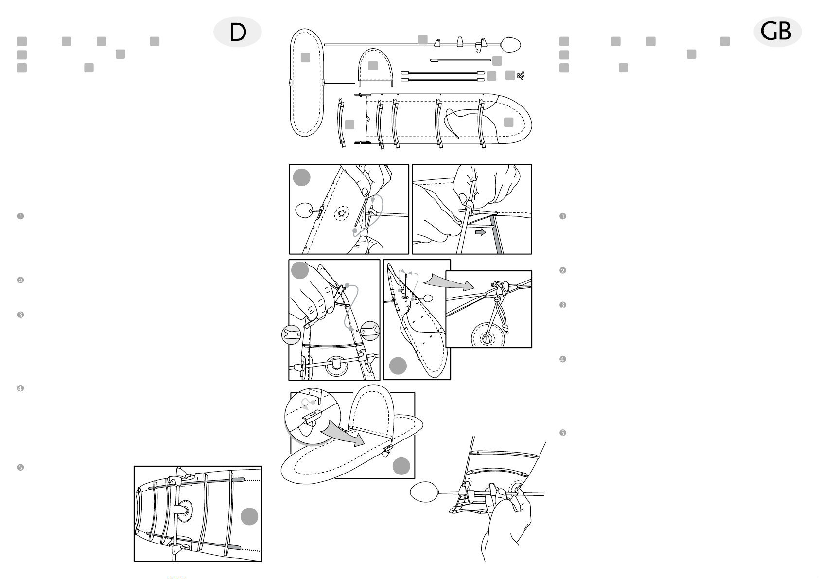
Breiten ie den Inhalt der Verpackung vor sich aus. Die einzelnen
Abbildungen werden Ihnen beim Zusammenbau helfen.
tecken ie die täbe der gefalteten Tragfläche zusammen, wie
in der Abbildung 1.1 gezeigt. Beim Einschieben des letzten tabes
ist einiges an Kraft erforderlich. Eine stabile Kante (Abb. 1.2) kann
dabei helfen die nötige pannung aufzubauen. Die Tragfläche
sollte danach möglichst nicht wieder auseinandergezogen werden,
da die Bespannung beschädigt werden könnte.
Montieren ie nun die 8 Rippen auf der Unterseite der Tragfläche.
Gehen ie dabei besonders vorsichtig vor. Achten ie auf die
Einbaurichtung (Abb. 2)
tecken ie den Mast in den Verbinder auf dem Rumpf, und zwar
durch die Öffnung in der Tragfläche. pannen ie die Takellage
mit Hilfe der kleinen chlaufen über die Nocke an der Mastspitze.
Achten ie bitte unbedingt darauf, dass die einzelnen chnüre
der Takellage nicht verdreht sind! Die Takellage sitzt sehr straff
 entsprechend kräftig muss man die letzte chlaufe in die Nocke
hebeln.
Das Höhenleitwerk wird wie in Abb. 4 gezeigt in das Ende des
Rumpfes bis zum Anschlag eingeschoben. Richten ie das
Höhenleitwerk parallel zur Tragfläche aus, und fixieren ie die
Rohre mit ein wenig ekundenkleber.
Achten ie beim Einstecken des eitenleitwerks auf die richtige
Einbaurichtung (flache Kurve nach vorn). Das Leitwerk läßt sich
über Justagelöcher im hinteren Verbinder auf Kurvenflug einstellen.
Die Tragflächenverstei-ungen
benötigen ie nur, wenn ie
den Airglider über den
Groundlauncher
katapultieren wollen. Dann
schieben ie die täbe so
wie in der Abbildung gezeigt
durch die Löcher in die vier
mittleren Rippen. Lösen ie
dazu vorher die Takelage.
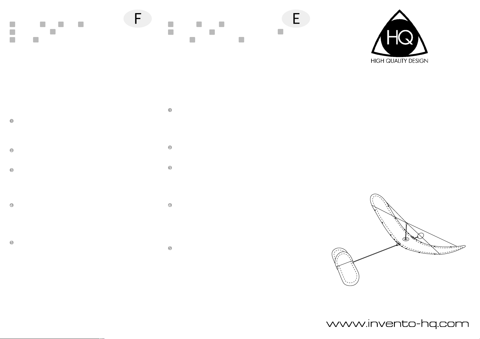
Handhaltung beim chleuderstart
Hand posture for hurl start
position de la main pour le lancer main
Sujeción manual para lanzar con catapulta
Inhalt  Contents  Contenu  Contenido Contents
1 Fuselage; 2 Mast; 3 upport surface; 4 8 ribs;
5 upport surface reinforcement; 6 Horizontal tail unit;
7 Rudder unit; 8 teel ballast with balancing.
Assembly
It is easy to assemble the Air Glider and due to the extensive
pre-assembly, it goes quickly. Work carefully and read these
instructions thoroughly because a mistake or large inaccuracy
will affect the flying properties of the model.
You will need some quick-dry adhesive.
Be careful when working with the quick-dry adhesive!
Children should assemble the Air Glider only with the help of
an adult. Prepare the package contents. The individual figures
may help during assembly.
Put the frames of the folded support surface together as shown
in Figure 1.1. ome force is needed to push the last frame in. A
stable edge (Fig. 1.2) can be useful in creating the necessary
tension. As much as possible, try not to pull the support surface
apart again to avoid damages from the tension.
Assemble the 8 ribs on the bottom of the support surface. Do
this very carefully. Ensure that the installation direction is correct
(Fig. 2).
tick the mast into the connectors on the fuselage; through the
opening in the support surface. Tighten the tackle using a small
loop over the cam on the tip of the mast. Ensure that the individual
lines of the tackle are not twisted. The tackle is very taut. You
have to use corresponding force to lift the last loop into the cam.
The horizontal tail unit is pushed into the end of the fuselage up
to the stop (as shown in Fig. 4). Align the horizontal tail unit
parallel to the support surface and secure the tubes with a little
quick-dry adhesive. Ensure correct installation position when
inserting the rudder unit (flat curve forward). The tail unit can be
adjusted to the flight curve via adjustment holes in the rear
connector.
You only need the support surface reinforcements if you plan to
catapult the Air Glider from a ground launcher. Then push the
rod through the holes in the four middle ribs (as shown in the
figure). To do this, loosen the tackle first.
2
8
7
43
1
1.1 1.2
2
3
4
5
1
6
5