15 16
Scan
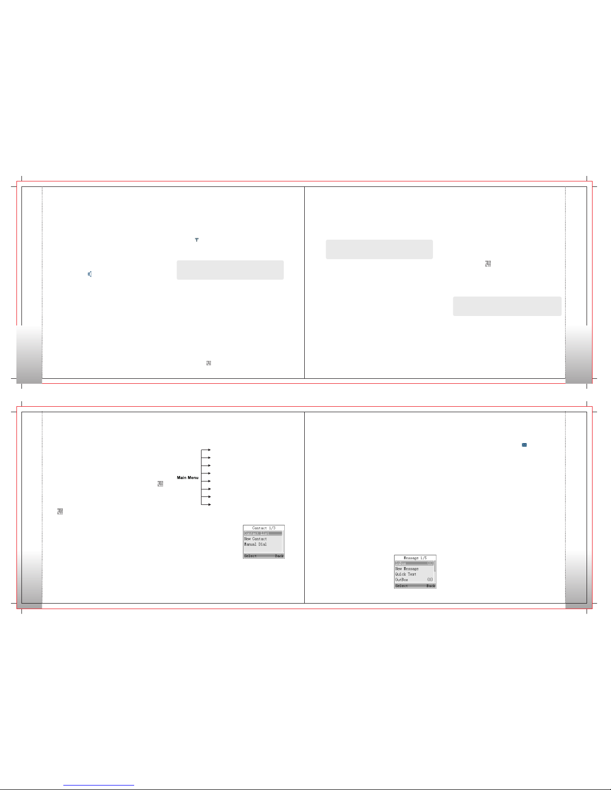
To access scan, press the
Menu key on home screen
and then select “Scan”.
Scan On/Off
Scan List
The function “Scan” allows you to listen to
communication activities on other channels so
that you can k e ep a c lo se track of your team
members. This option is used to enable or disable
the function.
You can request your dealer to create a scan list
for each channel. Each list may contain 32 channels
at most (eitherdigital channel or analog channel
is OK). After accessing the list, you can perform
any of the following operations:
• Adding a Channel
To include a new channel into the active scan list.
• Editing Priority Channel
To set the selected channel as a non-priority or a
priority channel. If you are interested in activities
17 18
on a channel, you can set it as a priority channel which
will be scanned more frequently than a non-priority
channel. Each scan lis t m ay contain two priority
channels at most. indicates priority channel 1, and
indicates priority channel 2.
• Deleting a Channel
To remove a channel from the active scan list. However,
the first channel in the list can not be deleted.
Drafts
The Drafts can save up to 10 draft messages. When
the Drafts is full, the messages will be overwritten
by the latest one automatically.
For each message, you can choose to perform any
of these operations: Send, Save and Delete.
To delete all messages in the Drafts, select “Message
->Drafts ->Delete All”.
Call Logs
To access this item, press the
Menu key in idle mode and
then select “Call Logs”, or press
the shortcut key for Call Logs
directly.
This radio can save up to 10 entries in the Outgoing List,
Incoming List and Missed List respectively. When the
memory for call logs is full, the oldest entry will be
overwritten by the latest one automatically.
After accessing a list and selecting an entry, you can
perform any of these operations: hold down the PTT
key to initiate a call; View Details or delete it.
To delete all entries in Outgoing List, Incoming List or
Missed List at a time, select "Call Logs -> Outgoing/
Incoming / Missed -> Delete All".
Zone
To access this item, press
the Menu key in idle mode
and then select “Zone”.
This radio supports up to 64 zones. You can use this
menu to select your desired zone.
Radio Settings
• Language
To access this item, press
the Menu key in idle mode
and then select “Settings”.
You can optimize your radio performance by customizing
related parameters according to actual needs and
your preferences.
Settings
• Tx Power
This option allows you to set transmit power level.
Alternatively, you can change th e power level
by pressing the shortcut key for Adjust Power
Level in idle mode.
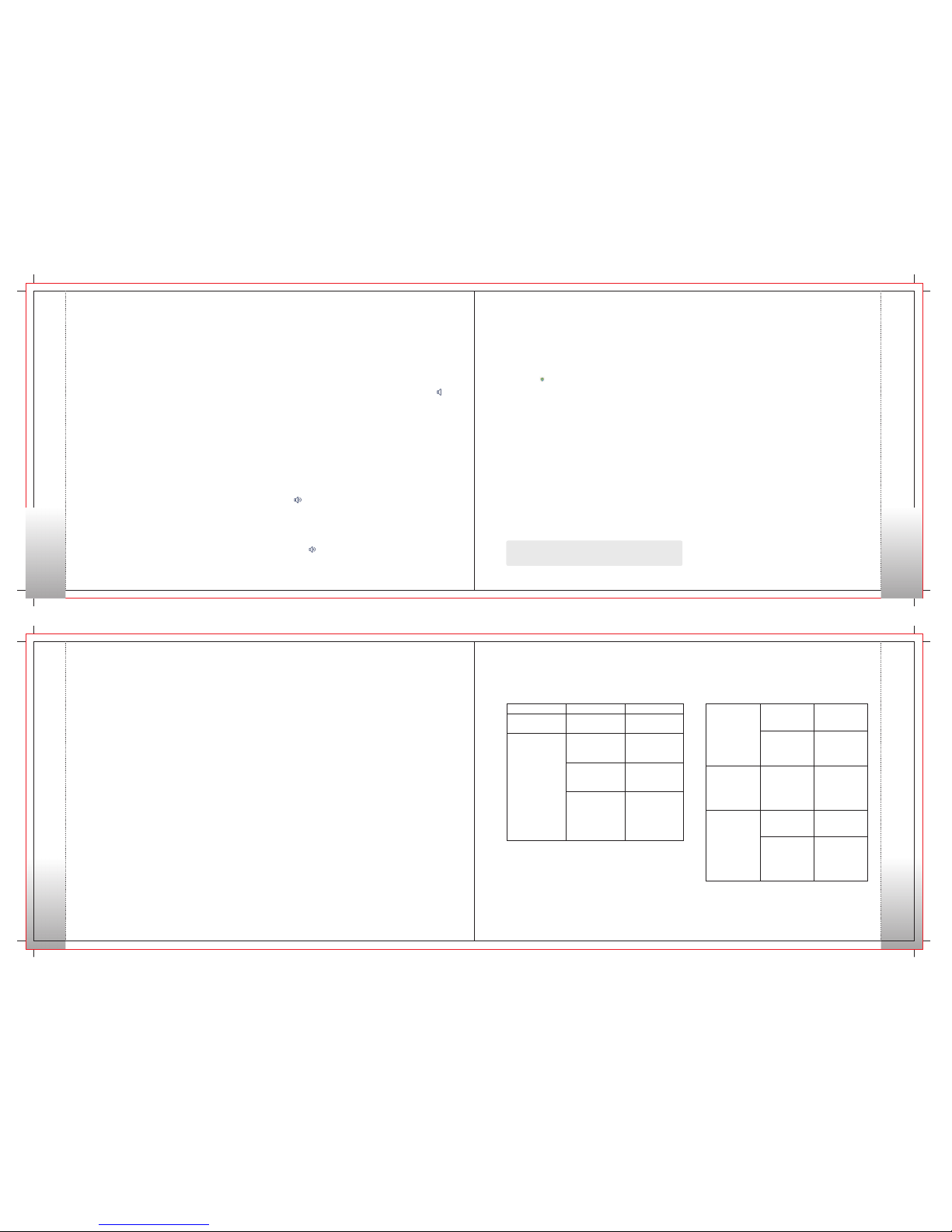
There are two levels available: High (indicated by )
and Low (indicated by ). High power level enables
you to communicate with farther team members.
Note: Power level should be set for each channel individually.
To set the language in which all interface information
is displayed. Currently, this radio only supports
two languages:Chinese and English.
• Lone Worker
This function can trigger off the Emergency mode
if the radio does not work for a certain time period.
This parameter determines whether to enable the
Lone Worker function.
• Tone
To set tones for your radio. You can set the following tones:
Radio Silent: to set whether the radio will give tone
indication. If Silent On is selected, all alerts will be off.
Call End Tone: to set whether the radio will give tone
indication when the call ends.
Private Call Tone: to set whether the radio will give
tone indication when the radio receives a private call.
Text Message Tone: to set whether the radio will give
tone indication when the radio receives a message.
Keypad Tone: to set whether the radio will give tone
indication when you are making keypad operations.
Group Call Tone: to set whether the radio will give
tone indication when the radio receives a group call.
Signaling Side Tone: to set whether the radio will
give tone indication when PTT is pressed (during
transmission of PTT ID);
• Squelch
This option allows you to select an appropriate squelch
level. Alternatively, you can change the squelch level by
pressing the shortcut key for Adjust Squelch Level in the
home screen.
There are three levels available: Tight, Normal and Open.
The default squelch level is “Normal”, and is often used in
low noise environment.
And generally, “Tight” is used in high noise
environment. It requires stronger signal for the
radio to unmute. However, if the squelch level
is set to Open, the speaker will keep unmuted
irrespective of the decoding conditions.
• Scrambler /Encrypt
To set whether to enable the Scrambler/Encrypt
feature.
• LED
All LEDs: to enable /disable all LED indications.
TX LED: to set whether the Tx LED indicates
during
RX LED: to set whether the Rx LED indicates
during reception.
Scan LED: to set whether the Scan LED indicates
in Scan mode.
Carrier LED: to set whether the Carrier LED indicates
when receiving carrier.
transmission.
• VOX
On/Off
If “On” is selected, it allows the user to make calls
every time the user speaks into the radio directly
without pressing the PTT key.
If “Off” is selected, the user should make calls by
pressing the PTT key.
Gain Level
The range of “Gain Level” is Level 1 to Level 9. The
lower the Gain Level is, the easier the VOX to be
enabled.
• Radio Password
Options: Off / On
When “On” is selected, users have to input the correct
Radio Lock Password to operate the radio normally.
When “Off” is selected, users can operate the radio
without inputting the password.
Radio Info
With this option, you can view the basic information
of your radio, including Serial Number, Radio Alias,
Frequency Range, Firmware Ver, Radio Data Ver and
Last Programmed Date.
Accessories
To access this item, press the
Menu key in idle mode and
then select “Accessories”.
GPS(Optional)
Operation:
1. To enable the feature:
Go to “Main Menu-> Accessories->GPS On/Off->
Off or On” and select “On”.
• GPS Update Time
This opti on defines the time interval to update
the GPS information. Range:1 – 60 seconds.
• Time Zone
Users can select a desired time zone from the
drop-do wn list. The r adi o a dju s ts i t s t im e
according to the selected time zone.
With this option, you can view longitude, latitude,
time, date, speed, altitude and SA (satellite)
information of your radio.
• Position
2. To disable the feature:
Go to “Main Menu->
Accessories->GPS On
/Off->Off or On” and select
“Off”
Menu Navigation
Menu Navigation
Menu Navigation
Menu Navigation