HS froggit FT-Comfort User manual

FT-Comfort
Manual
FT-Comfort Wireless Indoor 8-Channel
Thermo-Hygrometer

1. Introduction
Thank you for your purchase of the FT012TH Wireless Indoor 8-Channel Thermo-
Hygrometer with Display.
1.1 Indoor Thermo-Hygrometer Sensor Set Up
1. Remove the battery door on the back of the display, as shown in Figure 1. Insert
two AAA (alkaline or lithium, avoid rechargeable) batteries in the back of the
indoor sensor.
Figure 1
2. Insert two AAA batteries.
After inserting the batteries, All of the LCD segments will light up for a few seconds to
verify all segments are operating properly, and then icon flashes once per 60
seconds thereafter. Each time it flashes, the sensor is transmitting data.
3. Verify the correct channel number (CH) and temperature units of measure (°F vs.
°C) are on the display, as shown in Figure 2.

Figure 2
1. Temperature
2. Temperature units (°F or °C)
3. Temperature, Rate of Change
indicator
4. Temperature Calibrated Icon (when
the calibration is displayed )
5. Emission Icon (flashes when
updating)
6. Humidity, Rate of Change indicator
7. Min/Max Clears daily mode
8. Low power indicator
9. Humidity Calibrated Icon (when the
calibration is displayed )
10. Humidity Comfort Colorful Icon
11. Relative Humidity (%)
12. Channel 1,2,3,4,5,6,7,8 indictor
13. Min/Max Record mode
2. Display Features
2.1 Comfort Colorful Icon
The comfort icon is based on humidity ranges specified in Figure 3.
RH<45%
RH 45%~65%
RH >65%
Dry
Comfortable
Wet
Figure 3

2.2 Rate of Change Icon
The rate of change icon detects rapid changes in temperature and humidity. If the
arrow points upward, the temperature is increasing at a rate of +2°C per 30 minutes (or
greater), or humidity is increasing at a rate of +5% per 30 minutes (or greater). If the
arrow points downward, the temperature is decreasing at a rate of -2°C per 30 minutes
(or less), or humidity is decreasing at a rate of -5% per 30 minutes (or less).
3. Indoor Thermo-Hygrometer Sensor Operation
Note: The indoor sensor has three buttons for easy operation: MIN/MAX/- button,
SET button, and CH/+ button.
3.1 Indoor Sensor Channel Setting
Press and hold the CH/+ button 3 seconds until the scroll icon shows. In scroll mode,
press the CH/+ button to set up the channel number 1 through 8 channel. Press and
hold the CH/+ button 3 seconds to exit channel setting, scroll icon disappears.
Note: Set up the channel numbersBEFORE inserting the receiver batteries,
3.2 Min/Max Mode
The Min/Max mode displays the minimum and maximum temperature and humidity
(since reset of the unit) for the indoor sensor.
1. Display Maximum. Press the MIN/MAX button once to display the maximum.
The MAX icon will be displayed.
2. Clear Maximum. To reset the maximum values to the current values, press and
hold the MIN/MAX button for 3 seconds.
3. Display Minimum. Press the MIN/MAX button again to display the minimum.
The MIN icon will be displayed.
4. Clear Minimum. To reset the minimum values to the current values, press and
hold the MIN/MAX button for 3 seconds.
To return to normal mode, press the MIN/MAX button again.
3.3 Clearing Min/Max Daily
The minimum and maximum can be set to clear daily (at midnight) or manually. Press
and hold the SET button for 3 seconds to switch between and Clears Manually.
When is selected min/max reading will be cleared every 0:00 from the time you
clear it.
3.4 Temperature Units of Measure
The default temperature units of measure are degrees Celsius. To toggle between
degrees Celsius and degrees Fahrenheit, press and hold the MIN/MAX button for 3
seconds in normal mode.
3.5 Backlight Operation

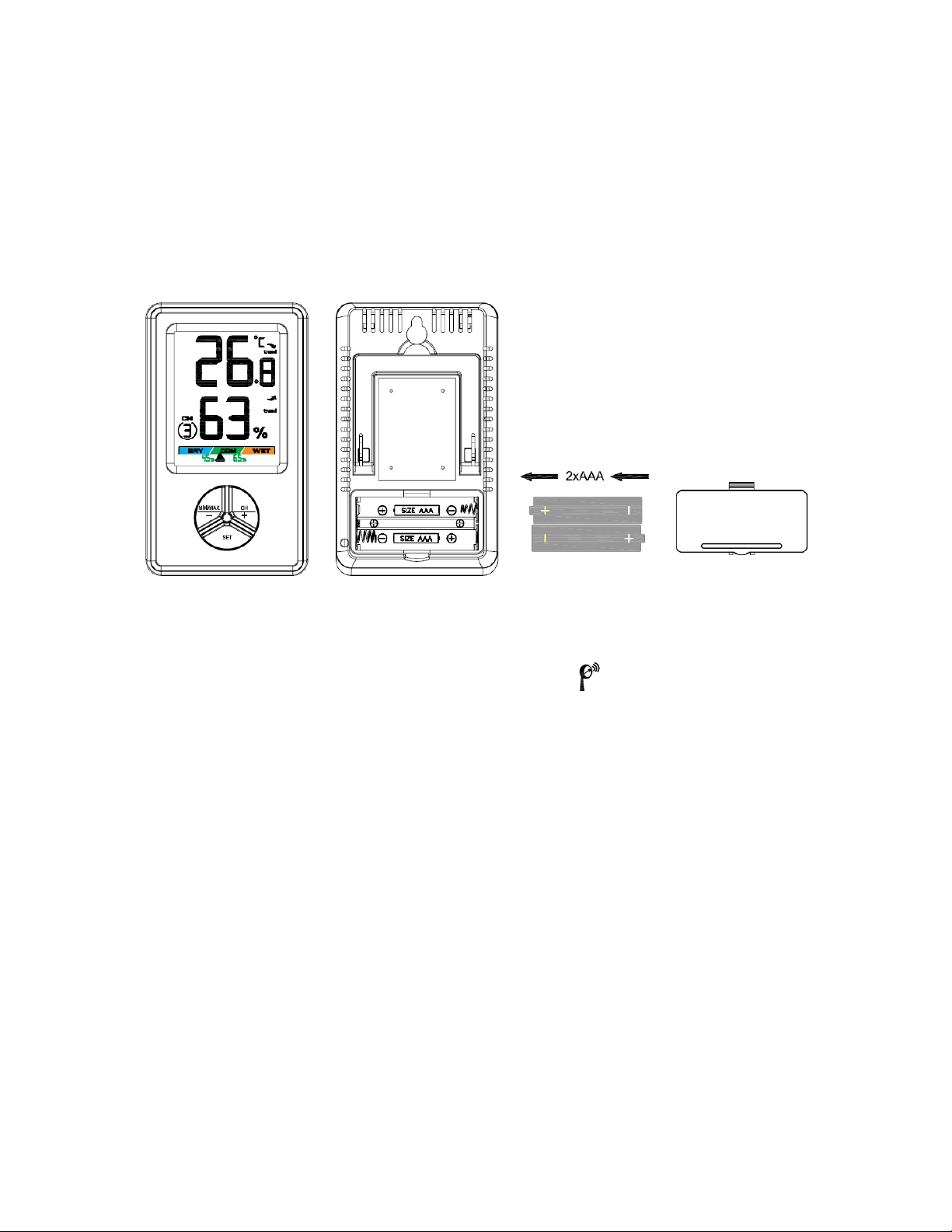
To temporarily turn on the back light for five seconds, press the any button on the indoor
sensor.
4Adjustment or Calibration
Note: The measured humidity range is between 10 and 99%. Humidity cannot be
accurately measured outside of this range. Thus, the humidity cannot be calibrated
below 10% or above 99%.
The purpose of calibration is to fine tune or correct for any sensor error associated with
the devices margin of error. The measurement can be adjusted from the console to
calibrate to a known source.
Calibration is only useful if you have a known calibrated source you can compare it
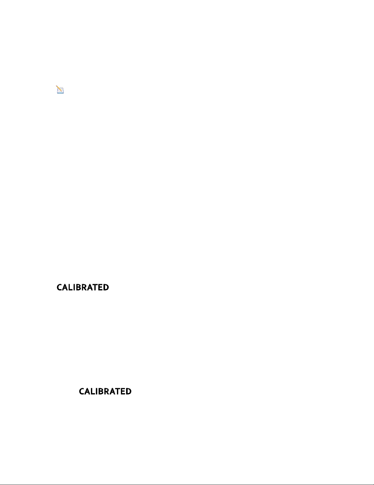
against, and is optional. This section discusses practices, procedures and sources for
sensor calibration to reduce manufacturing and degradation errors. Do not compare your
readings obtained from sources such as the internet, radio, television or newspapers.
They are in a different location and typically update once per hour.
The purpose of your weather station is to measure conditions of your surroundings,
which vary significantly from location to location.
4.1 Humidity Calibration
To enter the humidity calibration mode, press and hold the SET and MIN/MAX buttons at
the same time for 3 seconds and the humidity value will begin flashing. Press the CH/+
button to increase the humidity and the MIN/MAX/- button to decrease the humidity
reading in 1% increments. To rapidly increase (or decrease) the humidity reading, press
and hold the CH/+ or MIN/MAX/- button.
To return the humidity to the actual or uncalibrated measurement, press the SET button.
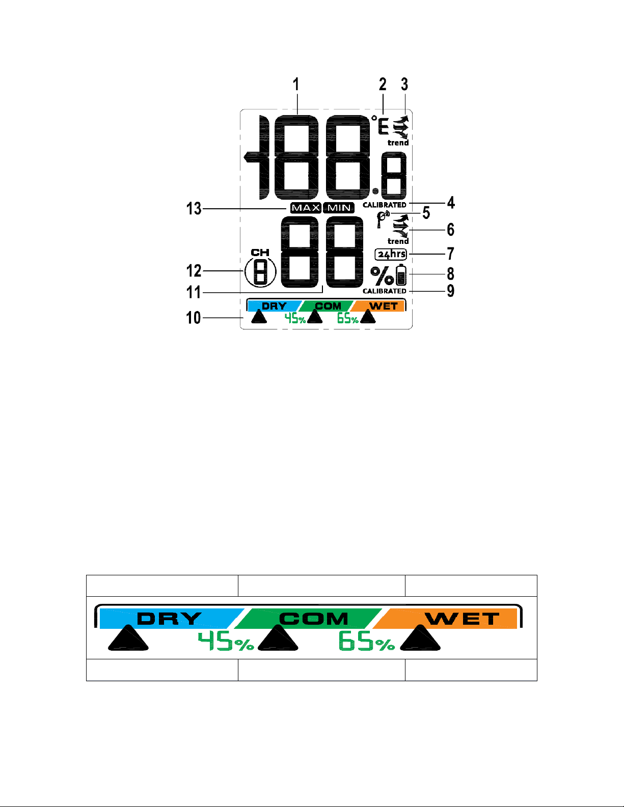
will be displayed when the humidity reading is a calibrated one.
After calibration is finalized, press and hold the SET button for three seconds, or wait 15
seconds for timeout, and the humidity value will stop flashing.
4.2 Temperature Calibration
To enter the temperature calibration mode, press and hold the SET and CH/+ buttons for
3 seconds and the temperature value will begin flashing. Press the CH/+ button to
increase the temperature and the MIN/MAX/- button to decrease the temperature
reading in 0.1° increments. To rapidly increase (or decrease) the temperature reading,
press and hold the CH/+ or MIN/MAX/- button.
To return the temperature to the actual or uncalibrated measurement, press the SET
button. will be displayed when the temperature reading is a calibrated
one.
After calibration is finalized, press and hold the SET button for three seconds, or wait 15
seconds for timeout, and the temperature value will stop flashing.

Discussion:Temperature errors can occur when a sensor is placed too close to a
heat source (such as a building structure, the ground or trees).
To calibrate temperature, we recommend a mercury or red spirit (fluid) thermometer. Bi-
metal (dial) and other digital thermometers are not a good source and have their own
margin of error. Using a local weather station in your area is also a poor source due to
changes in location, timing (airport weather stations are only updated once per hour) and
possible calibration errors (many official weather stations are not properly installed and
calibrated).
Place the sensor in a shaded, controlled environment next to the fluid thermometer, and
allow the sensor to stabilize for 48 hours. Compare this temperature to the fluid
thermometer and adjust the console to match the fluid thermometer.
4.3 Sensor Operation Verification
Verify the humidity match closely with the console and sensor array in the same location
(about 5 to 10’ apart). The sensors should be within 10% (the accuracy is ± 5%). Allow
about 30 minutes for both sensors to stabilize.
Verify the temperature match closely with the console and sensor array in the same
location (about 1.5m to 3m apart). The sensors should be within 2°C(the accuracy is ±
1°C). Allow about 30 minutes for both sensors to stabilize.
4.4. Indoor Sensor Installation
Indoor use only. It is recommended you mount the Indoor sensor on a north
facing wall, in a shaded area. Direct sunlight and radiant heat sources will result
in inaccurate temperature readings. Use a screw or nail (not included) to affix the
indoor sensor to the wall, as shown in Figure 4.
Figure 4
Or put it on the table. Place the console at least three feet away from computers, TVs
and wireless phones. Avoid transmitting through solid metal barriers. as shown in Figure
5.

Figure 5
4.5 Best Practices for Wireless Communication
Wireless communication is susceptible to interference, distance, walls and metal
barriers. We recommend the following best practices for trouble free wireless
communication.
1. Electro-Magnetic Interference (EMI). Keep the console several feet away from
computer monitors and TVs.
2. Radio Frequency Interference (RFI). If you have other 433.9MHz devices and
communication is intermittent, try turning off these other devices for
troubleshooting purposes. You may need to relocate the transmitters or receivers
to avoid intermittent communication.
3. Line of Sight Rating. This device is rated at 100 meter line of sight (no
interference, barriers or walls) but typically you will get 30 meter maximum under
most real-world installations, which include passing through barriers or walls.
4. Metal Barriers. Radio frequency will not pass through metal barriers such as
aluminum siding. If you have metal siding, align the remote and console through
a window to get a clear line of sight.

5. Specifications
5.1 Wireless Specifications
Line of sight wireless transmission (in open air): 100 meters, 30 meters under
most conditions.
Frequency: 433.9 MHz(+/-250K)
Update Rate: 60 seconds
5.2 Measurement Specifications
The following table provides specifications for the measured parameters.
Measurement
Range
Accuracy
Resolution
Indoor Temperature
0 to 60 °C
± 1 °C
0.1 °C
Indoor Humidity
10 to 99%
± 5% (only
guaranteed between
20 to 90%)
1 %
5.3 Power Consumption
Indoor sensor : 2 x AAA 1.5V Alkaline or Lithium batteries (not included)
Battery life: Minimum 12 months for indoor thermometer-hygrometer sensor ,
Backlight often light may reduce the battery life.
6. Troubleshooting Guide
Problem
Solution

Problem
Solution
Wireless remote (thermo-
hygrometer) not reporting in to
console.
If any of the sensor communication is lost,
The maximum line of sight communication range
is 100 meters and 30 meters under most
conditions. Move the sensor assembly closer to
the display console.
If the sensor assembly is too close (less than 5’),
move the sensor assembly away from the display
console.
Make sure the remote sensor LCD display is
working and the transmitter light is flashing once
per 48 seconds.
Install a fresh set of batteries in the remote
thermo-hygrometer. For cold weather
environments, install lithium batteries.
Make sure the remote sensors are not
transmitting through solid metal (acts as an RF
shield), or earth barrier (down a hill).
Move the remote sensors around electrical noise
generating devices, such as computers, TVs and
other wireless transmitters if used indoor.
Move the remote sensor to a higher location.
Move the remote sensor to a closer location.
Temperature sensor reads too high
in the day time.
Make sure the thermo-hygrometer is mounted in a
shaded area on the north facing wall.
Indoor and Outdoor Temperature do
not agree
Allow up to one hour for the sensors to stabilize
due to signal filtering. The two temperature
sensors should agree within 2 °C (the sensor
accuracy is ± 1 °C).
Indoor and Outdoor Humidity do not
agree
Allow up to one hour for the sensors to stabilize
due to signal filtering. The two humidity sensors
should agree within 10 % (the sensor accuracy is
± 5 %).
Display contrast is weak
Replace console batteries with a fresh set of
batteries.

Notes on the return of batteries according to §12 BatterieVO: Batteries do not belong in
the household waste. Please dispose of all batteries as required by law, disposal in
domestic waste is expressly prohibited. Batteries and rechargeable batteries can be
dispensed free of charge at municipal collection points or in the shops on the spot.
This manual may not be reproduced in any form without the written permission of the
publisher, even in excerpts.
This manual may contain errors and misprints. However, the information in this manual
is regularly reviewed and corrections made in the next issue. We accept no liability for
technical errors or printing errors, and their consequences.
All trademarks and copyrights are acknowledged.
www.froggit.de
HS Group GmbH & Co. KG
Escherstr.31
50733 Koeln
Germany
Telefon
E-Mail
0221 / 367 48 05
Registergericht Amtsgericht Koeln
HRA 26493
Komplementaer: HS Group
Verwaltungsgesellschaft mbH
Sitz Koeln
Registergericht Amtsgericht Koeln
HRB 64734
Geschaeftsfuehrer: Peter Haefele,
Carl Schulte
UStId DE237971721
WEEE Reg. Nr. 66110125
declaration of conformity

Hereby we declare, HS-Group GmbH & Co.KG, Escherstr. 31, 50733 D-Cologne, that
this product is in compliance with the essential requirements and other relevant
provisions of Directive 1999/5 / EC.
The declaration of conformity for this product can be found at: www.froggit.de or on
request.
This manual suits for next models
1
Table of contents
Other HS Weather Station manuals
Popular Weather Station manuals by other brands

La Crosse Technology
La Crosse Technology V21V3 Faqs

La Crosse Technology
La Crosse Technology WS-9031U instruction manual

Oregon Scientific
Oregon Scientific WMR100 user manual

Gira
Gira 1010 00 installation instructions

Sygonix
Sygonix 2754782 operating instructions

brennenstuhl
brennenstuhl WID 550 owner's manual