ProWeatherStation TP3000WC User manual

8000060 Rev 1 5-May-18
1
Solar Powered Wireless Wi-Fi Weather Station
TP3000WC Operation Manual
About this manual
Thank you and congratulations on selecting this professional weather
station! We are sure you will enjoy the benefits of accurate weather
readings and the precise network time information that this weather
station offers. This manual will guide you step-by-step through setting up
your device. Use this manual to become familiar with your
ProWeatherStation, and save it for future reference.
Glossary of Common Terms
LCD
“LCD” is an acronym for ”Liquid Crystal Display”. This is a common type
of display screen used in televisions, computers, watches, and digital
clocks.
BAROMETER & BAROMETRIC PRESSURE
A barometer is a device that measures the pressure of the air pushing on
it—this measurement is called the barometric pressure. We don’t
actually feel the barometric pressure because the air pressure is pushing
equally in every direction.
RELATIVE AIR PRESSURE
Relative air pressure is the same as the barometric pressure. The
calculation of relative air pressure is a combination of the absolute air
pressure and the altitude.
ABSOLUTE AIR PRESSURE
Absolute air pressure is the actual air pressure on the barometer without
regard to altitude.

8000060 Rev 1 5-May-18
2
INCHES OF MERCURY (inHg)
Inches of Mercury is the common unit of measurement for air pressure in
the United States.
HECTOPASCALS (hPa)
Hectopascals are the common units of measurement for air pressure in
the International System (SI) of measurement. The hectopascal holds
the same value
Important Note:
The ProWeatherStation TP3000WC comes fully assembled for ease of
use. The Outdoor Sensor array runs mainly on solar power which
charges a super capacitor located inside the unit, but has 2 AA batteries
for backup power when needed (ie; solar panel shaded or covered with
snow). The outdoor sensor array communicates with the display console
over a 915Mhz RF signal which sends the data to the display console
about every 48 seconds. The display console can be run on batteries to
just display the weather readings or it can be powered using the included
5V adapter to enable the WiFi capabilities of the display console. Once
the unit is connected to a local WiFi network the display console can
upload data automatically to Weather Underground without the need for a
PC and can also be accessed from a PC running the WeatherSmartIP
Wifi software.

8000060 Rev 1 5-May-18
3
OVERVIEW
Display console
Features
Time and date, Moon phase.
Indoor temperature and humidity
Outdoor temperature and humidity
Wind chill, gust, wind direction.
Rainfall - Displays rain level and rainfall data in 24 hours, one week,
one month, one year, total rain and rainfall event.
Wind speed in mph, km/h, m/s, knots or Beaufort
Wind direction with 360 degrees
Wind chill, dew point and heat index temperature display.
Barometric, weather forecast.
MAX, MIN value with time stamp. High/ low alarm.
Light and UV index
NonVolatile Memory: Saves the data when batteries are changed
WeatherSmartIP Wifi PC software
Uploads the data to 3 weather server: wunderground.com, Weathercloud
and WOW
Back light
5VDC connector

8000060 Rev 1 5-May-18
4
Proweatherstation Setup
Warning: Any metal object may attract a lightning strike,
including your weather station mounting pole. Never install the
weather station during a storm.
Warning: Installing your weather station in a high location may
result in injury or death. Perform as much of the initial checkout and
assembly on the ground, preferaby inside a building or home. Only
install the weather station on a clear, dry day.
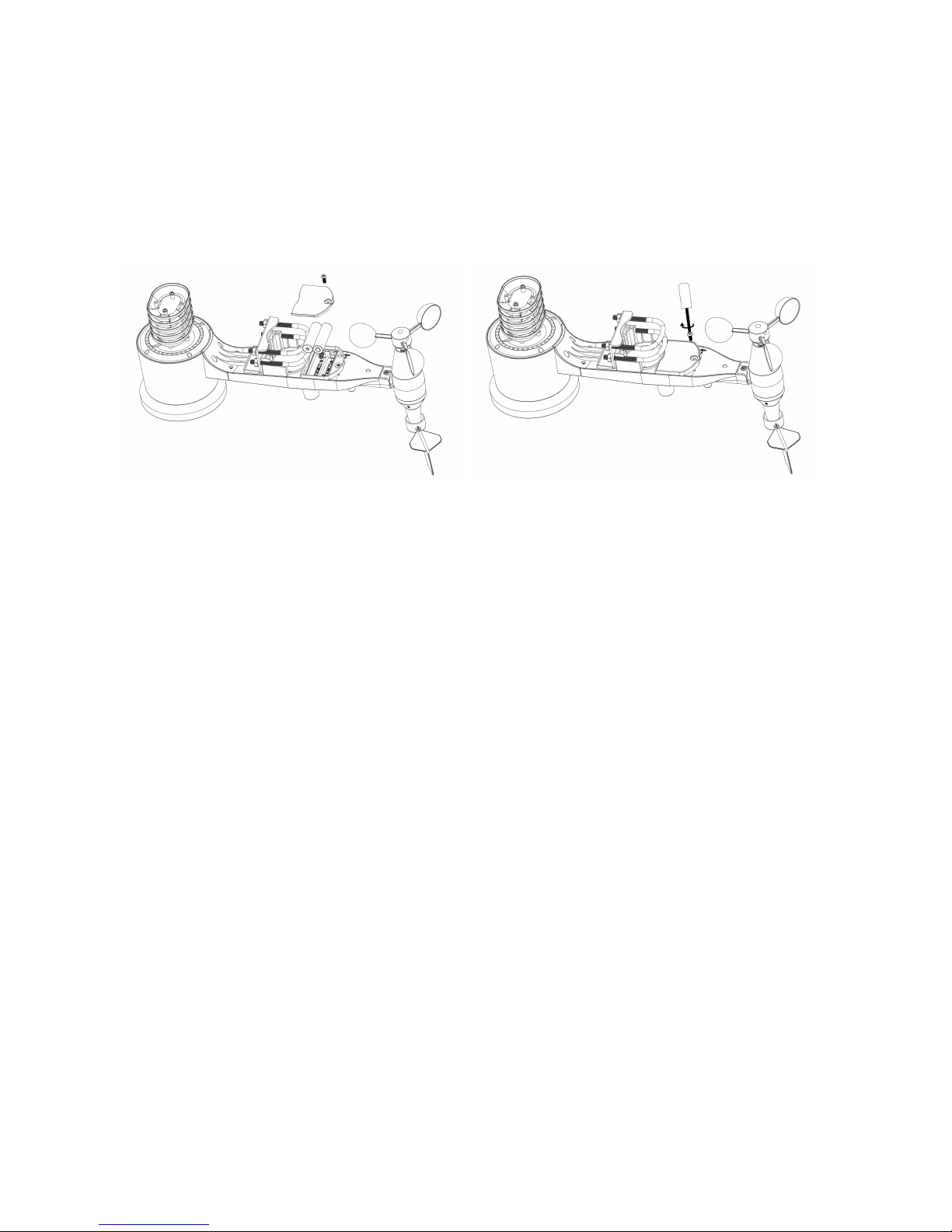
1. Sensor Array Components
Figure 1
1. Wind Vane
2. Wind Speed Sensor
3. UV sensor/ Light sensor
4. Solar panel
5. Rain collector
6. Temp/Humidity sensor
7. Bubble level
8. U-Bolt
9. LED Indicator: light on for 4s if the unit power up. Then the LED will
flash once
every 16 seconds (the sensor transmission update period).
10. Battery door
11. Reset button
8000060 Rev 1 5-May-18
5
2. Install Batteries
Insert 2XAA batteries in the battery compartment. The LED indicator
on the back of the transmitter will turn on for four seconds and
normally flash once every 16 seconds (the sensor transmission
update period).
Figure 5 Figure 6
Note: If no LED lights up or is lit full time, make sure the battery is
inserted with correct polarity. Caution! Do not install the batteries
backwards as you can permanently damage the outdoor sensor.
If LED function is not as expected, remove the batteries, wait 30
seconds and then re-install.
Note: We recommend lithium batteries for cold weather climates, but
alkaline batteries are sufficient for moderate climates. Rechargeable
batteries should never be used, because they have lower voltages.
3. Mount outdoor sensor
Reference Figure 8 & 9. The mounting assembly includes two U-Bolts
and a bracket that tightens around a 1 to 2” diameter pole (included)
using the four U-Bolt nuts.

8000060 Rev 1 5-May-18
6
Note: Use the bubble level beside the rain sensor as a guide to verify
that sensors are level.
4. Reset Button and Transmitter LED
In the event the sensor array is not transmitting, reset the sensor
array.
With an open ended paperclip, press and hold the RESET BUTTON
for 3 seconds to initiate a reset: LED turns on while RESET button is
pressed, and resumes normal operation after the Reset button is
released: LED will flash every 16s during normal operation.
Figure 10
Figure 8
Figure 9
8000060 Rev 1 5-May-18
7
5. Best Practices for Wireless Communication
Wireless communication is susceptible to interference, distance,
walls and metal barriers. We recommend the following best practices
for trouble free wireless communication.
1. Electro-Magnetic Interference (EMI). Keep the display console
several feet away from computer monitors and TVs.
2. Radio Frequency Interference (RFI). If you have other 915 MHz
devices and communication is intermittent, try turning off these
other devices for troubleshooting purposes. You may need to
relocate the transmitters or receivers to avoid intermittent
communication.
3. Line of Sight Rating. This device is rated at 300 feet line of sight
(no interference, barriers or walls) but typically you will get 100
feet maximum under most real-world installations, which include
passing through barriers or walls.
4. Metal Barriers. Radio frequency will not pass through metal
barriers such as aluminum siding. If you have metal siding, align
the remote and console through a window to get a clear line of
sight.
The following is a table of reception loss vs. the transmission medium.
Each “wall” or obstruction decreases the transmission range by the
factor shown below.
Medium
RF Signal Strength Reduction
Glass (untreated)
5-15%
Plastics
10-15%
Wood
10-40%
Brick
10-40%
Concrete
40-80%
Metal
90-100%

8000060 Rev 1 5-May-18
8
6. Display Unit Setup
1. Display Console Layout:
1.Time
2.Indoor Temperature
3.Indoor Humidity
4.Barometric Pressure
5. Barometric Pressure graph
6.Weather Forecast icon
7. Dynamic information display area
8.RF signal
9. Alarm icon
10. Memory status
11.Wind direction
12.Rain fall
13.Wind speed/Gust speed
14.wind chill/Dew point/Heat index
15.Outdoor Humidity
16.Outdoor Temperature
17.UV index
18.Light
19.Date
20.Wifi Signal icon
2. Initial Display Console Set Up
1. The unit will turn on all segments of the LCD for 3 seconds after
power. Then the unit will start to register the outdoor sensor

8000060 Rev 1 5-May-18
9
array which takes ~3 minutes.
2. Full display
3. Key function
8000060 Rev 1 5-May-18
10
SET: Enter the setting mode
ALARM: Display high or low alarm function / turn on/off the alarm
HISTORY: Display history records / return to normal mode
MAX/MIN: Display the MAX, MIN value
: Move to previous information( normal mode) or +
( programming mode)
: Move to next information( normal mode) or– ( programming
mode)
:: Move to previous segment/move to main menu during
setting.
:: Move to next segment/ move to sub menu during setting.
Console Operation
Note: Many display console settings can be set in the
WeathersmartIP WiFi PC software. In order to do this, the
software needs to be installed on a PC and the display console
needs to be connected to your WiFi network. Instructions are
located later in this user guide.
Program mode
The screen is divided into 10 segments for selection and there are
message display panel on the bottom.
There are six program modes: normal, setting mode, history mode, alarm
mode, max/min mode and calibrated mode.
All the modes can be exited at any time by pressing the HISTORY key, or
waiting for a 30 second timeout to take effect.
Normally, if the segment selected have multi parts, press SET key to
choose different part. Example: the current section is RAIN, you can
press SET key to alternate the display of RAIN RATE, RAIN EVENT, DAY,
WEEK, MONTH, YEAR and TOTAL.

8000060 Rev 1 5-May-18
11
1. Quick Display Mode(Update every 5 Seconds)
In the normal mode press” ”or” ” key to switch among different
segments. The respective chosen segment will be marked with the arrow
symbol” ”. And there will be corresponding information display on the
message board which is the lower 2 lines on the screen.
The 11 digits on left are used to display text, the right side displays figures.
The display will automatically switch after a few seconds. Or use the “ ”
or “ ” keys to manually switch the display.
If there are alarms occurred, the alarm information will be displayed in
real time as well.
Time and date
If the arrow symbol “ ” is in this segment, following information will
appear on message board:
a) Year, Weekday
b) Alarm time and status of the alarm(on/off)
c) Moon phase. (Reference Section Other Console Functions/Moon
phase for detail)
d) If connected with Wi-Fi, the device time will synchronize with the
internet time(UTC Time, you need to set the time zone for local
time).
8000060 Rev 1 5-May-18
12
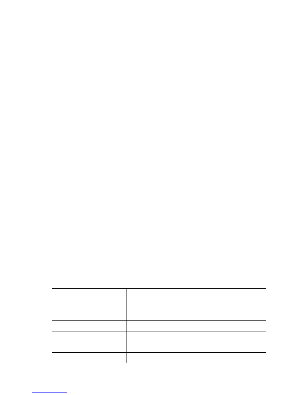
Light and UVI
If the arrow symbol “ ” is in this segment, following information with
time stamp will appear on message board:
a) The max light strength value of the day.
b) The max light strength value since the last reset
c) The max UV index value of the day.
d) The max UV index value since the last reset.
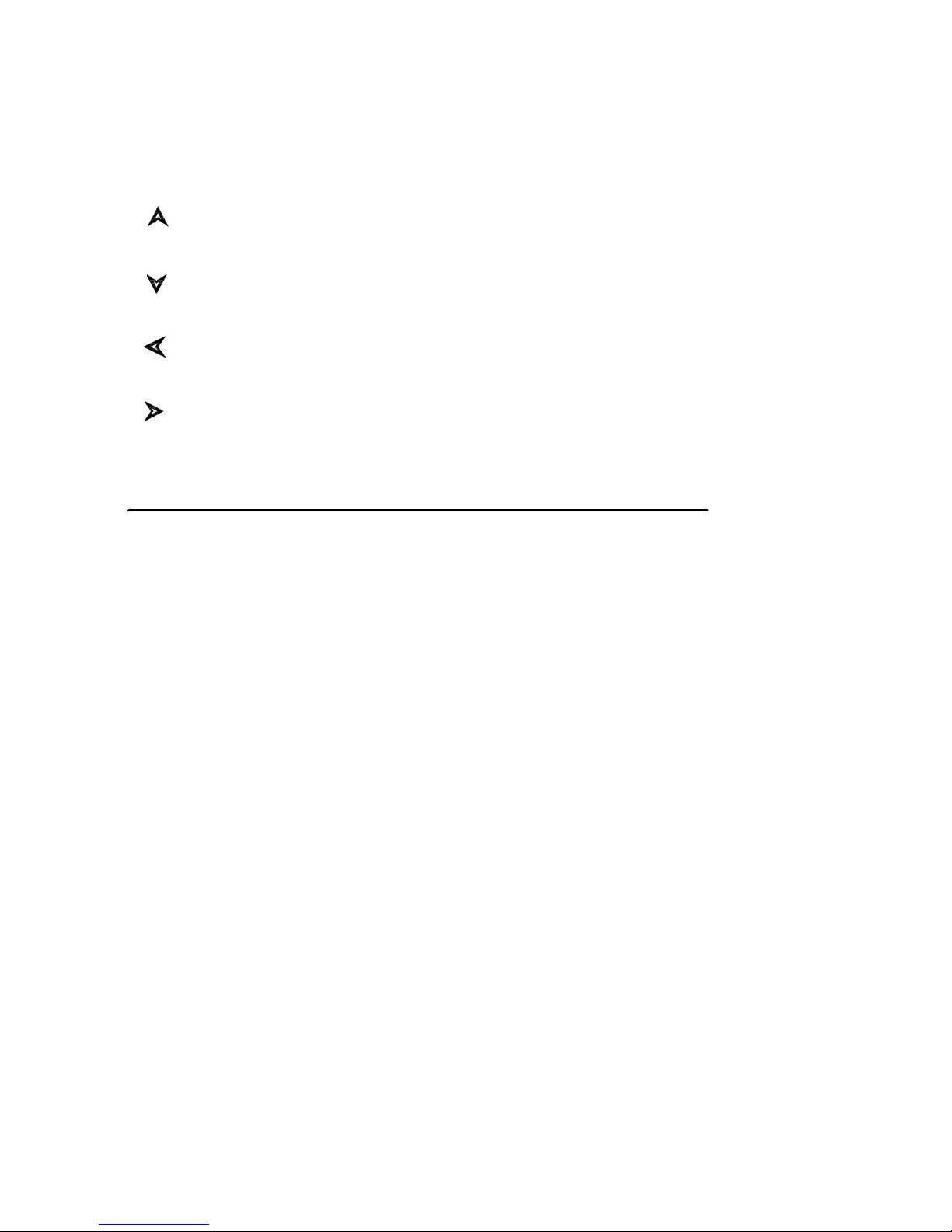
Indoor temperature
If the arrow symbol “ ” is in this segment, following information with
time stamp will appear on message board:
a) Max indoor temperature value of the current day.
b) Min indoor temperature value of the current day.
c) Max indoor temperature value since the last reset
d) Min indoor temperature value since the last reset
e) Max indoor humidity value of the current day.
f) Min indoor humidity value of the current day.
g) Max indoor humidity value since the last reset
h) Min indoor humidity value since the last reset
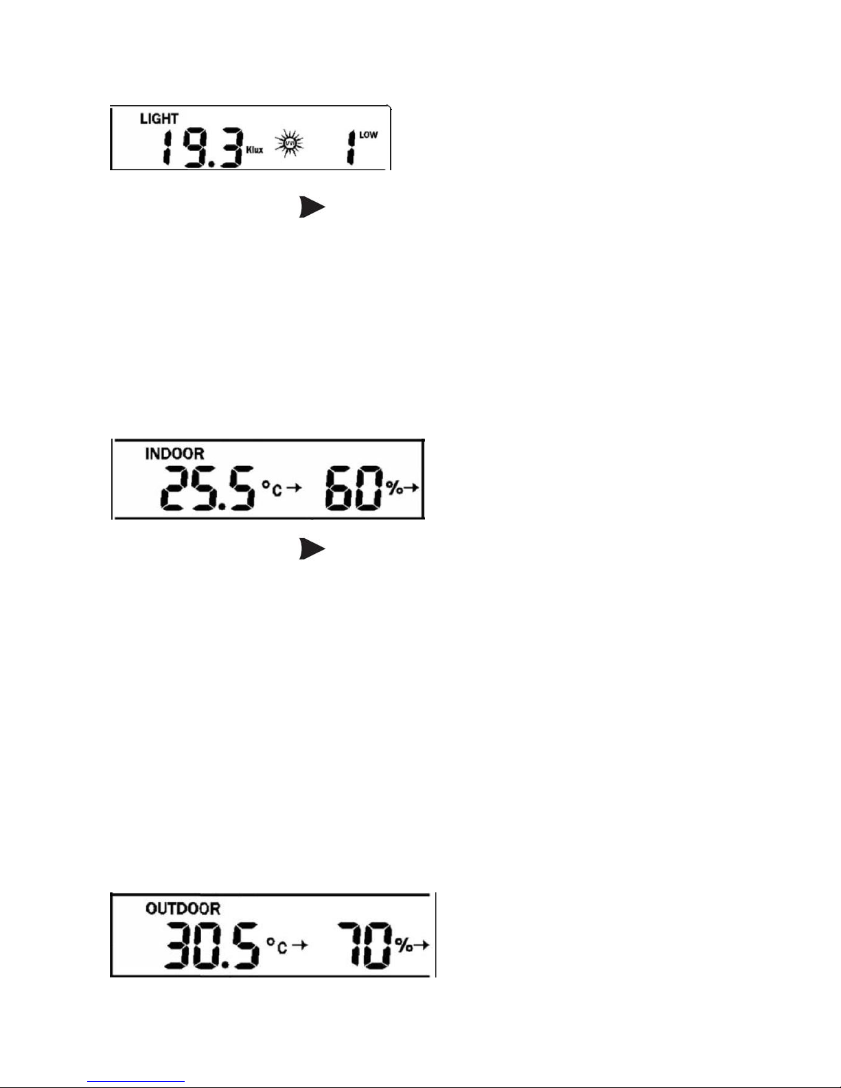
Outdoor temperature/ humidity

8000060 Rev 1 5-May-18
13
If the arrow symbol “ ” is in this segment, following information with
time stamp will appear on message board:
a) Max outdoor temperature value of the current day.
b) Min outdoor temperature value of the current day.
c) Max outdoor temperature value since the last reset
d) Min outdoor temperature value since the last reset
e) Max outdoor humidity value of the current day.
f) Min outdoor humidity value of the current day.
g) Max outdoor humidity value since the last reset
h) Min outdoor humidity value since the last reset
Barometric
If the arrow symbol “ ” is in this segment, following information with
time stamp will appear on message board:
a) Max relatively barometric pressure of the current day
b) Min relatively barometric pressure of the current day
c) Max relatively barometric pressure since the last reset
d) Min relatively barometric pressure since the last reset
e) Max absolute barometric pressure of the current day
f) Min absolute barometric pressure of the current day
g) Max absolute barometric pressure since the last reset
h) Min absolute barometric pressure since the last reset
8000060 Rev 1 5-May-18
14
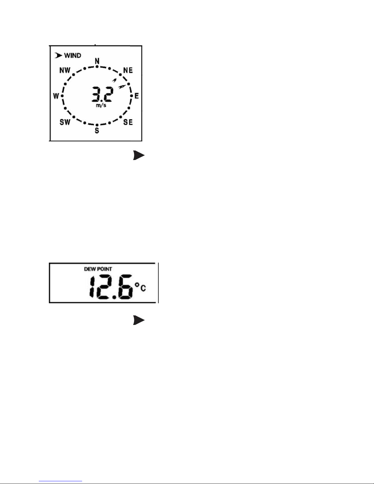
Wind and gust speed
If the arrow symbol “ ” is in this segment, following information with
time stamp will appear on message board:
a) The max wind speed of the current day
b) The max wind speed since the last reset.
c) The max wind gust speed of the current day
d) The max wind gust speed since the last reset.
Wind chill, dew point, heat index
If the arrow symbol “ ” is in this segment, following information with
time stamp will appear on message board:
a) Min wind chill temperature of the current day
b) Min wind chill temperature since the last reset
c) Max dew point temperature of the current day
d) Min dew point temperature of the current day
e) Max dew point temperature since the last reset
f) Min dew point temperature since the last reset
g) Max heat index of the day of the current day.
h) Max heat index of the day since the last reset
8000060 Rev 1 5-May-18
15
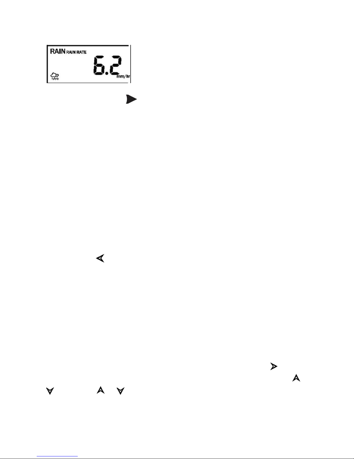
Rainfall
If the arrow symbol “ ” is in this segment, following information with
time stamp will appear on message board:
a) Max rain rate of the current day
b) Max rain rate since the last reset
c) Max Rainfall data of current day
d) Max Rainfall data of last week
e) Max Rainfall data of last month
f) Max Rainfall data of last year
2. Setting Mode
2.1 In normal mode, press SET key for 2 seconds to enter the setting
mode.
Then press ” ”button to transfer among different setting function :
TIME SETTING
UNIT SETTING
RECORD SAVE INTERVAL
RAIN SEASON SETTING
BAROMETRIC SETTING
KEY BEEP SETTING
CALIBRATION SETTING
TRANSMITTER ID
When the desired setting function is displayed, press the ” ” key to
start the associated setting menu. Change a setting with the key /
.Hold the / key for 2 seconds will increase/decrease digits in
great steps. Press HISTORY key or wait for 30 seconds at any time,
device will return to normal mode.

8000060 Rev 1 5-May-18
16
TIME SETTING
After entering setting mode, the first setting function “TIME
SETTING” will appear on message board. Use the ” ” key to select
the desired sub functions:
a) TIME FORMAT:12H/24H
b) DATE FORMAT:MM-DD-YYYY / DD-MM-YYYY / YYYY-MM-DD
select
c) TIME: Manual setting of time and date
d) TIME ZONE
e) DAYLIGHT SAVING TIME: switch on/off the reception of DST.
f) NORTH/SOUTH: Set northern/southern hemisphere for moon
phase
UNIT SETTING
After entering setting mode, the first setting function ”TIME
SETTING” will appear on message board. Press” ”key to switch
to “UNIT SETTING” display.
Then use the ” ” key to select the desired sub functions:
a) Light unit select (lux, fc, w/m2)
b) Temperature unit select (C, F)
c) Pressure unit select (hpa, inhg, mmhg)
d) Wind speed unit select (km/h, mph, knots, m/s, bft)
e) Rainfall unit select (mm, inch)
RECORD SAVE INTERVAL: to set the interval of data recording.
Under setting mode, the first setting function appear on message
board is ”TIME SETTING”, Press” ”key repeatedly to switch to
“RECORD SAVE INTERVAL” display.
Use the ” ” key to start setting of recording interval.
Use the / keys to select the desired recording interval for
measured values.

8000060 Rev 1 5-May-18
17
RAIN SEASON SETTING
Under setting mode, the first setting function appear on message
board is ”TIME SETTING”. Press” ”button repeatedly to switch to
“RAIN SEASON SETTING” display.
Press the ” ” button to start setting of the month of rain season.
Press the / buttons to select the month from January to
December.
Rain season is the time of year when most of a region’s average
annual rainfall occurs. Rain season influence the annual rainfall
maximum, minimum and total value. When one month was selected,
the annual rainfall and annual max/min rainfall were zero clearing at
0:00 of the first day of the selected month.
PRESSURE SETTING
Under setting mode, the first setting function appear on message
board is ”TIME SETTING”. Press” ”button repeatedly to switch to
“BAROMETRIC SETTING” display.
Then press the ” ” button to select the desired sub functions:
BAROMETRIC COORDINATES: Press / buttons to change
the historical graph time between 12 and 24 hours.
KEY BEEP SETTING
Under setting mode, the first setting function appear on message
board is ”TIME SETTING”. Press” ”button repeatedly to switch to
“KEY BEEP SETTING” display.
Use the ” ” button to start setting button beep.
Press / buttons to switch on/off the button beep.
Calibration setting
a) IN TEMP OFFSET

8000060 Rev 1 5-May-18
18
Offset for indoor temperature.
b) IN HUMI OFFSET
Offset for indoor humidity.
c) OUT TEMP OFFSET
Offset for outdoor temperature.
d) OUT HUMI OFFSET
Offset for outdoor humidity
e) ABS PRESS OFFSET
Offset for absolute barometric pressure.
f) REL PRESS OFFSET
Offset for relatively barometric pressure.
g) WIND DIR OFFSET
Wind direction can be adjusted by 0-359°.For southern hemisphere
installations, the wind direction need to change by 180°.
h) WIND SPEED
Wind speed calibration coefficient: default 1 (range is Range is
0.1-2.5)
i) RAINFALL FACTOR
Rain factor calibration coefficient: default 1 (range is Range is
0.1-2.5)
j) RAIN DAY CALIBRATION
Calibration for total rain falls of 1 day. (Range is 0-9999mm)
k) RAIN WEEK CALIBRATION
Calibration for total rain falls of 1 week (Range is 0-9999mm)
l) RAIN MONTH CALIBRATION
Calibration for total rain falls of 1 month (Range is 0-9999mm)
m) RAIN YEAR CALIBRATION
Calibration for total rain falls of 1 year (Range is 0-9999mm)
n) RAIN TOTAL CALIBRATION
Calibration for total rain falls since last reset. (Range is 0-9999mm)
Transmitter ID
Display the transmitter ID.

8000060 Rev 1 5-May-18
19
3. ALARM MODE
In normal mode, press ALARM key you will enter high alarm mode, and
press ALARM key again you will switch to low alarm mode.
HIGH ALARM SETTING
Press / key to transfer among the different segments and
press / key to adjust the value of the high alarm.
a) TIME ALARM –Set time alarm.
b) In TEMP HIGH ALARM --Set indoor temperature high alarm
c) In HUMI HIGH ALARM --Set indoor humidity high alarm
d) Out TEMP HIGH ALARM Set outdoor temperature high alarm
e) Out HUMI HIGH ALARM Set outdoor humidity high alarm
f) ABS BARO HIGH ALARM --Set absolute barometric pressure high
alarm
g) REL BARO HIGH ALARM --Set relatively barometric pressure high
alarm
h) WIND HIGH ALARM --Set wind speed high alarm
i) GUST HIGH ALARM --Set gust speed high alarm
j) DEW POINT HIGH ALARM --Set dew point high alarm
k) HEAT INDEX HIGH ALARM --Set heat index high alarm
l) RAIN RATE HIGH ALARM --Set rainfall rate high alarm
m) RAIN DAY HIGH ALARM --Set rainfall day high alarm
LOW ALARM SETTING
a) In TEMP LOW ALARM--Set indoor temperature low alarm
b) In HUMI LOW ALARM --Set indoor humidity low alarm
c) In TEMP LOW ALARM --Set outdoor temperature low alarm
d) OUT HUMI LOW ALARM --Set outdoor humidity low alarm
e) ABS BARO LOW ALARM --Set absolute barometric low alarm
f) REL BARO LOW ALARM --Set relatively barometric low alarm
g) WIND CHILL LOW ALARM --Set wind chill low alarm
h) DEW POINT LOW ALARM --Set dew point low alarm

8000060 Rev 1 5-May-18
20
Under alarm mode, press the SET button to switch on or/off the alarm.
Press the ALARM button to switch between high alarm and low alarm
setting.
Press HISTORY button or wait for 30 seconds at any time to return to
normal mode.
When the alarm is activated, the alarm icon will be displayed on the
right of message board.
When an alarm is triggered, the base station will emit a sound beep and
the alarm icon flashes. The corresponding text alarm message
appears on the message board. Press any button to stop sound beep.
But the alarm icon will continue to flash if the weather data still
above or below the threshold.
4. Max/Min Mode
In Normal Mode, press the MIN/MAX button to enter the max/min mode.
In this mode, you can view all minimum/maximum records of weather
parameters.
Press MIN/MAX to switch among below records:
TODAY MAX—The maximum values during current day
HISTORY MAX –The maximum values since last reset
TODAY MIN --The minimum values during current day
HISTORY MIN --The minimum values since last reset
Press / button to switch among max/min records of different
parameter, together with the time and date stamp.
Each Maximum/minimum value can be cleared by pressing SET button
Table of contents


