HTP MTS 210 User manual

180 Joey Drive
Elk Grove Village, IL 60007-1304
Ph: (847) 357-0700 · Fax: (847) 357-0744
Web: www.usaweld.com
Owner’s Manual
MIG 200i
MTS 210
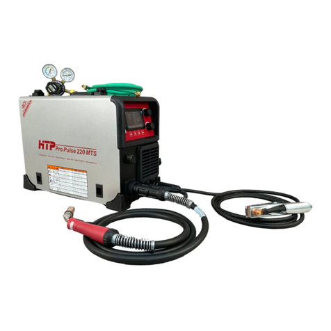
Pro Pulse 220 MTS
Scan for
video manual

2
Foreword
Thank you for purchasing a new HTP® Inverter MIG welder. This manual covers the HTP MIG 200i, the HTP MTS 210,
and the HTP Pro Pulse™ 220 MTS. All three welders feature HTP’s advanced one knob Synergic Control. The MIG 200i
is an analog, full synergic welder with an Easy Set feature. The MTS 210 is an advanced, multi-process, full synergic
welder with a digital LCD. The Pro Pulse 220 MTS is our advanced, multi-process, full synergic, pulse MIG welder. The
Pro Pulse 220 MTS produces high quality, virtually spatter free welds on all common metals when you use the correct gas
and consumables for your welding application. By following the instructions closely, you can achieve success when
welding with the Pro Pulse 220 MTS, even when welding aluminum where the margin of error is very small (when
welding aluminum, almost everything must work out just right in order to achieve good results). This does not mean that a
novice welder will not be able to perform aluminum welds successfully with the Pro Pulse 220 MTS. No matter your skill
level, the more knowledge you have about the operation of your HTP welder and the specific welding processes, the more
likely you are to produce professional results. HTP provides this manual and some videos to familiarize and help you
weld successfully with your new HTP welder.
Customers interested in the Pro Pulse 220 MTS often ask us the following questions: If I buy the Pro Pulse 220 MTS, will
I be able to weld aluminum right out of the box? and Why do some customers find welding with the Pro Pulse 220 MTS
difficult? Why do some customers, including customers with decades of regular MIG welding experience, struggle when
welding with the Pro Pulse 220 MTS, even after reading the entire manual twice and watching several videos? First,
many of our customers successfully weld aluminum with the Pro Pulse 220 MTS within hours, not days. Second,
experienced welders struggle when welding with the Pro Pulse 220 MTS for multiple reasons, including the following:
Muscle Memory. Operators who typically MIG weld steel are accustomed to holding the gun close to the work piece,
and the frying bacon sound the machine makes when welding. Operators may be thrown off by the sound the Pro
Pulse 220 MTS makes when welding, and muscle memory causes the operator to keep the gun too close to the work
piece when welding aluminum, which requires a 3/4” to 1” CTWD (contact tip to work distance).
Old Habits and Frugalness. For aluminum welding (all spray arc transfer and pulse), your gas flow rate must be
significantly higher than for classic MIG welding (steel). Flow rates must be set between 35 and 50 CFH. We also see
operators running economy Asian import wire or random wound wire. For aluminum welding, where everything must
be just right, a bad roll of wire can make a bad day in aluminum welding. We recommend using a high-quality wire.
Currently, HTP sells Alcotec wire, which is a premium quality, precision wound wire that is made in the U.S.A. We
found that Alcotec wire works best with the Pro Pulse 220 MTS. We do not recommend using 1 lb., 4” diameter
spools.
Unrealistic Expectations. No matter what, MIG welds will never look identical to TIG welds. Although, when the
settings on your machine and the movement of your hand are in perfect harmony in a double pulse program, they can
come pretty close.
Also, when everything works right, welding aluminum is a lot like welding steel, though there are a few differences—
from the gas, to the MIG welding gun, to the consumables, to consumable use. When welding aluminum, even a
skilled welder may go through a few contact tips before finishing a roll of wire; unlike when welding steel, where
some operators can weld an entire 30 lb., 12” diameter spool of wire with one tip. Aluminum requires more contact
tips because it is welded in spray transfer, where it is more likely to burn back into the tip because of high heat. As a
novice welder, you may go through five to ten contact tips in the first few hours or the first day.
Birds nesting is not an issue with the Pro Pulse 220 MTS. However, burn back may occur and must be addressed
immediately—failure to do so will result in EXCESSIVE tip usage! When burn back occurs, the damaged tip
becomes useless and must be replaced. Furthermore, run about 10’ of wire through your MIG gun to discard any wire
damaged by slipping in the drive roll (which occurs due to burn back into the contact tip).
Material Thickness Rating Displayed in the Machine. We designed this feature to give you an idea about settings
(wire speed and voltage). The ratings displayed, generally speaking, are designed for straight line, push or pull
(depending on the application) welds, made at a rather fast travel speed (to reduce heat input and distortion) and
without any gun manipulation (no weaving, swirly motion, etc.). However, depending on the joint configuration (butt,
lap, or t-joint) and on the welding position (flat, horizontal, vertical up or down, and overhead), you need to adjust the
synergic settings accordingly.
Now, with a better understanding of what you will experience when welding with the Pro Pulse 220 MTS, read the rest of
the manual and watch the accompanying videos for a more thorough explanation of the machines’ features.
3
Index
Manufacturer’s Warranty 4
Safety Suggestions 4-6
MIG 200i Specifications 7
MTS 210/Pro Pulse 220 MTS Specifications 8
Electrical Connections 9
General Characteristics
MIG 200i
MTS 210/Pro Pulse 220 MTS
9
10-12
MIG 200i Front Panel Controls 13
MIG 200i Front Panel Connections 14
MIG 200i Operation 15-16
MTS 210/Pro Pulse 220 MTS Front Panel Controls 17
MTS 210/Pro Pulse 220 MTS Express Welding 17
MTS 210/Pro Pulse 220 MTS Programs Overview 18
Welding Aluminum w/the MTS 210 or Pro Pulse 220 MTS 18-19
MTS 210/Pro Pulse 220 MTS Front Panel Connections 20
MTS 210/Pro Pulse 220 MTS Operation
Stick Welding
TIG Welding
MIG Welding
General Info
MIG 2T
MIG 4T
Stitch Welding
21
21-22
22
23-25
26
26
MTS 210/Pro Pulse 220 MTS JOB Mode 27-28
MTS 210/Pro Pulse 220 MTS Remote Control Options 28
Trouble Shooting 29
Duty Cycle & Over-Heat Protection
MIG 200i
MTS 210/Pro Pulse 220 MTS
30
31
HTP 15 Series MIG Welding Gun 32
HTP 24 Series MIG Welding Gun 33
HTP 26 Series MIG Welding Gun 34
MIG 200i Wiring Diagram 35
MIG 200i Parts Diagram 36
MIG 200i Parts List 37
MIG 200i Wire Feed Assembly Parts Diagram & List 38
MTS 210/Pro Pulse 220 MTS Wiring Diagram 39
MTS 210/Pro Pulse 220 MTS Parts Diagram 40
MTS 210/Pro Pulse 220 MTS Parts List 41
Appendix I
MTS 210 Program List
Pro Pulse 220 MTS Program List
42
43
Appendix II: Glossary 44

4
Manufacturer’s Warranty
It is expressly agreed that there are no warranties, expressed or implied, made by either the Salesman, Dealer, or HTP
America, Inc. on products or parts furnished hereunder, except the Manufacturer’s Warranty against defective
materials or workmanship as follows:
HTP America, Inc. warrants each new welding machine to be free from defects in material and workmanship under
normal use and service for Three (3) Years after delivery to the original purchaser. HTP America, Inc. will repair and
replace, at its factory, any part or parts thereof. Products should be returned to HTP America, Inc., with transportation
charges prepaid, and which its examination shall disclose to its satisfaction to have been thus defective. This warranty
being in lieu of all other warranties, expressed or implied, and all other obligations or liabilities on its part and it
neither assumes nor authorizes any person to assume for it any liability in connection with the sale of its machines.
This warranty shall not apply to any welding machine which has been repaired or altered by unauthorized service
departments in any way so as, in the judgment of HTP America, Inc., to affect its stability and reliability, nor which
has been subjected to misuse, negligence, or accident.
HTP America, Inc. shall not be liable in any event, unless HTP America, Inc. receives notice of alleged breach of
warranty, actual or constructed, specifying the claimed defect within not more than Thirty (30) Days after discovery.
HTP America, Inc. has reserved the right to make changes in design or add any improvements to its products, at any
time, without incurring any obligation to install the same on equipment.
This warranty is void unless warranty card is sent to HTP America, Inc. within Fifteen (15) Business Days from the
date of purchase.
Exclusions to Warranty:
1. The MIG Welding Gun is warrantied for a period of Ninety (90) Days against defects in material and
workmanship.
2. The contact tips, tip holders, gas diffusers, gas nozzles, and liner are consumable items, WHICH CARRY NO
WARRANTY.
Note: This warranty is to the or iginal pur chaser only. The war r anty can be transferred to another owner , with
HTP’s approval, for a warranty transfer fee. HTP America, Inc. must be notified within Fourteen (14) days of the sale
and must be provided with the contact information of the original owner, the contact information of the new owner,
and the serial number of the machine.
Safety Suggestions
It is forbidden for people with PACEMAKERS to use or come near the machine.
Electric arc welding produces ultra-violet rays, which are harmful to skin and eyes. Ultr a-violet radiation can
penetrate lightweight clothing, reflect from light-colored surfaces, and burn the skin and eyes.
Wear a heavy, pocket-less, long-sleeved shirt, cuff-less trousers, and high-topped work shoes.
Wear a full-faced welding helmet with a number ten or darker shade and a cap.
Electric arc welding produces flying sparks and hot material, which can cause fire.
To avoid fire, do not weld on wood, plastic tile, or carpeted floors. Concrete or masonry floors are safest.
Do not weld on pressurized containers.
Do not weld on drums, barrels, tanks, or other containers until they have been cleared and cleaned as described in
AWS Standard A6.01.
Do not wear flammable materials.
Wear non-oily/non-greasy, flameproof welding gloves; any oil or grease on gloves may ignite.
Avoid having any type of fuel, such as cigarette lighters or matches, on your person as you weld.
Ensure that there is a fire extinguisher in the welding area.

5
Noise can damage your hearing. Protect yourself suitably to avoid hear ing damage.
The welding arc can cause burns. Keep the tip of the welding gun/torch far from your body and from other
persons.
Electric arc welding produces toxic fumes.
Provide adequate ventilation in the welding area at all times.
Do not weld on galvanized zinc, cadmium, or lead beryllium materials unless you are POSITIVE that sufficient
ventilation is provided. These materials produce toxic fumes.
Do not weld in areas close to degreasing or spraying operations. Chlorinated hydrocarbon vapors may react with
the ultra-violet rays and form highly toxic phosphate gas.
If you develop momentary eye, nose, or throat irritation during welding, stop welding immediately. This is an
indication that ventilation is not adequate. Do not continue to weld until ventilation is improved.
ELECTRIC SHOCK CAN KILL.
Exposed, electrically hot conductors, other bare metal in the welding circuit, or ungrounded, electrically hot
equipment can fatally shock a person whose body becomes a conductor. Do not stand, sit, lie, lean on, or touch a wet
surface when welding.
Disconnect the power supply before working on the welding machine.
Do not work with deteriorated or damaged cables.
Frequently inspect cables for wear, cracks, and damage. Replace those with excessively worn insulation to avoid
a possible lethal shock from bare cable.
Do not touch bare electrical parts.
Ensure that all of the panels covering the welding machine are firmly secured in place when the machine is
connected to the power supply.
Insulate yourself from the workbench and from the floor (ground); use insulating footwear and gloves.
Keep gloves, footwear, clothes, the work area, and the welding equipment clean and dry.
Check the machine power cable frequently; the power cable must be free from damage to the insulation. BARE
CABLES ARE DANGEROUS. Do not use the machine if the power cable is damaged; a damaged power cable
must be replaced immediately.
If it is necessary to open the machine, first disconnect the power supply. Wait Five (5) Minutes to allow the
capacitors to discharge. Failure to take this precaution may expose you to the dangerous risk of electric shock.
For more information, refer to the following standards and comply as applicable.
ANSI Standard Z49.1 SAFETY IN WELDING AND CUTTING, obtainable from the American National
Standards Institute, 1430 Broadway, New York, NY 10018.
ANSI Standard Z87.1 SAFE PRACTICE FOR OCCUPATIONAL AND EDUCATIONAL EYE AND FACE
PROTECTION, obtainable from the American National Standards Institute, 1430 Broadway, New York, NY
10018.
AWS Standard A6.0 WELDING AND CUTTING CONTAINERS WHICH HAVE HELD COMBUSTIBLES,
obtainable from the American Welding Society, 2051 NW 7th St., Miami, FL 33125.
NFPA Standard 51 OXYGEN-FUEL GAS SYSTEMS FOR WELDING AND CUTTING, obtainable from the
National Fire Protection Association, 470 Atlantic Ave., Boston, MA 02210.
NFPA Standard 51B CUTTING AND WELDING PROCESSES, obtainable from the National Fire Protection
Association, 470 Atlantic Ave., Boston, MA 02210.
CGA Pamphlet P-1 SAFE HANDLING OF COMPRESSED GASES IN CYLINDERS, obtainable from the
Compressed Gas Association, 500 Fifth Ave., New York, NY 10036.
OSHA Standard 29 CFR, Part 1910, Subpart Q WELDING, CUTTING, AND BRAZING.

6
Fig. 1

7
MIG 200i Specifications
Maximum Output Amperage 200A
Minimum Output Amperage 20A
Maximum Recommended Thickness 1/4”
Duty Cycle
20% @ 180A (104º F)
60% @ 110A (104º F)
100% @ 90A (104º F)
Arc Voltage 13 to 35V
Open Circuit Voltage 85V
Cooling Fan
Wire Size .023” to .035”
Input Voltage 208 to 240V
Input Amperage 34A
Frequency 50/60Hz
Wire Feed Rate (In./Min.) 55 to 630 IPM
Size
Length
Width
Height
19-3/4”
10”
14-1/2”
Weight 39 Lbs.
Lifting
Weight:
Power Source Alone: 39 Lbs.
Power Source + 11 Lb. Spool of Wire: 50 Lbs.
Power Source + 33 Lb. Spool of Wire: 72 Lbs.
Lifting by Hand: You may lift the power sour ce with or without an 11 Lb. spool of wire installed.
ATTENTION! Do not lift the power source with a 33 Lb. spool of wire installed. Remove the 33 Lb. spool of
wire before lifting the power source.

8
MTS 210 & Pro Pulse 220 MTS Specifications
Maximum Output Amperage 200A (220A for 10 seconds on the Pro Pulse 220 MTS
only)
Minimum Output Amperage MIG: 12A
TIG & Stick: 4A
Maximum Recommended Thickness
*Single pass capacity varies depending on the material
being welded and the setting of the machine.
1/4” to 3/8”
Duty-Cycle
35% @ 200A (77º F)
100% @ 140A (77º F)
25% @ 200A (104º F)
60% @ 140A (104º F)
100% @ 120A (104º F)
Open Circuit Voltage 75V
Electronic Overload Protection Yes
Cooling (On-demand, electric fan, variable speed) Air
Wire Spool Capacity
*Up to a 44 Lb. weight capacity; 8” spools recommended
for Double Pulse aluminum welding.
8” & 12”
Wire Diameter
*Depends on the material being welded (not all wire can
be welded in all sizes.
.023” to .045”
Input Voltage 208 to 240V
Input Amperage MIG & TIG: 35A
Stick: 40A
Frequency 50/60 Hz
Wire Feed Rate (In./Min.) 55 to 630 IPM
Size
Length
Width
Height
19-3/4”
10”
14-1/2”
Weight
*Without wire and cables. 42 Lbs.

9
Electrical Connection
MIG 200i
Your MIG 200i operates on single-phase, 230V power (208V-240V). The machine draws 34 amps out of the wall
when operating at a welding output of 200 amps. If you operate the machine on a generator, it needs to be a clean
power generator with a minimum of 8500 watts (8500 watts must be the continuous rating or running watts rating of
the generator, NOT the peak rating or starting watts rating of the generator).
MTS 210 & Pro Pulse 220 MTS
Your MTS 210 or Pro Pulse 220 MTS operates on single-phase, 230V power (208V-240V). The machine draws 35
amps out of the wall when operating at a MIG or TIG welding output of 200 amps. 200 amps of Stick welding
output requires 40 amps of 230V input. If you operate the machine on a generator, it needs to be a clean power
generator with a minimum of 8500 watts (8500 watts must be the continuous rating or running watts rating of the
generator, NOT the peak rating or starting watts rating of the generator) for MIG or TIG operation. Stick operation
requires a 10,000 watt generator. If you operate the machine in MIG or TIG on an extension cord, the wire size of
the cord needs to be at least 10AWG and should not exceed a length of 100’.
General Characteristics
HTP inverter MIG welders, which feature electronic adjustments controlled by a microprocessor, allow you to
achieve excellent welding quality thanks to the advanced technologies applied. The microprocessor circuit controls
and optimizes arc transfer irrespective of the load variation and impedance of the welding cables. The inverter
technology used in our welding machines enabled us to achieve the following:
Compact, lightweight welders
Reduced energy consumption
Excellent dynamic response
Very high power factor and yields
Better welding characteristics
The sensitive electronic components used in our inverter MIG welders are cooled with forced air by fans with low
noise production, and our inverter welders also feature sophisticated, electronic overheat protection to prevent
damage to your machine.
MIG 200i
The MIG 200i is a synergic welding machine that features an incredible arc dynamic, which makes the MIG 200i
suitable for any kind of wire and for any material thickness from 26 gauge up to 1/4”. With the MIG 200i, you can
weld in manual mode or in synergic mode with Easy Set™ technology. The Easy Set feature makes set up a breeze
by automatically setting your welder, in a couple of simple steps, to the correct parameters. A simple polarity
reversal allows you to weld with gas (solid wire) or without gas (flux-cored wire). The MIG 200i also features
manual wire feed (“jog”), manual gas purge, and start speed adjustment.
NOTE: The HTP MIG 200i is not suitable for thawing pipes.
The MIG 200i package includes:
HTP MIG 200i Power Source
10’ 15 Series MIG Welding Gun
10’ Ground Clamp and Cable Assembly
Flowmeter
6’ Gas Hose
Owner’s Manual

10
MTS 210 & Pro Pulse 220 MTS
The MTS 210 operates the same way as the Pro Pulse 220 MTS. The only difference between the two machines is
that the MTS 210 does not offer any of the pulse programs found in the Pro Pulse 220 MTS. You can upgrade the
MTS 210 to a Pro Pulse 220 MTS by adding the pulse module to the front panel logic board later for a fee.
The MTS 210 and the Pro Pulse 220 MTS are synergic welding machines.
The key feature of a synergic welding machine is the ease of set up. In the past, you needed charts from wire
manufacturers to determine wire speed and voltage, as well as CTWD (contact tip to work distance) of different
welding applications, which ultimately determined the arc length and also indicated which shielding gas to use. With
the MTS 210 and the Pro Pulse 220 MTS, this information is preprogrammed and displayed to you. Both machines
feature an LCD that allows you to select a synergic program for a specific wire, such as steel, aluminum, stainless
steel (available on the Pro Pulse 220 MTS only), silicon bronze, etc. Once you select a program, the machine tells you
which gas to use and then allows you to select the thickness of the material being welded. After selecting the synergic
program and the material thickness, the machine automatically sets the correct wire feed speed (in inches per minute,
or IPM) and the matching voltage to achieve the best welding results. Of course, since you will encounter atypical
situations, especially during repairs on used or dirty material, the machine gives you the option to adjust the settings
either colder or hotter by reducing or increasing the voltage.
The MTS 210 and the Pro Pulse 220 MTS also offer an ST-arc function. The ST-arc function reads welding
parameters back to the welding machine live (while welding). The ST-arc function monitors and maintains the arc
length, while allowing the stick-out (CTWD) to vary. ST-arc allows the new welder to focus on the location of the
weld, as well as the travel speed, while allowing the experienced welder to keep a perfectly uniform weld bead and
uniform heat input. This enables the welder to achieve good welds in tight corners—a feat that couldn’t previously be
achieved with conventional welding equipment.
What is pulsed process MIG welding?
Pulsed process welding is a form of welding that happens in spray arc transfer, while classic MIG welding is done in
short arc, or short circuit, transfer and sounds somewhat like frying bacon. Spray arc welding is a lot hotter, has
excellent penetration, and is typically very quiet (mostly a quiet hissing with an occasional crackle). This form of
welding is so hot that it typically can only be used in flat position or horizontal position. Pulse gives you the option to
run the process out of position while retaining the same desirable characteristics of deep penetration—a virtually
spatter-free, leak tight weld with excellent bead appearance—but does so while enabling you to join materials of
different thicknesses at increased travel speed, all while lowering the heat input and distortion.
Pulsed process MIG welding is different than pulsed TIG welding. In the MIG process, filler material has to be added
constantly to maintain the welding arc, and this sets the ground rules for the pulse function. When pulsing with TIG,
you have the ability to adjust peak current, background current, pulse ON time, and pulse frequency. When using
pulsed process MIG, on the other hand, you typically only have the choice of pulse ON or pulse OFF. However, the
Pro Pulse 220 MTS offers peak pulse (in some programs, under certain conditions, and up to 300 amps), pulse ON
time, as well as background current—all preprogrammed, according to scientific studies for best results, at the
factory. The pulse frequency adjusts with the wire speed; slower wire speeds have a lower frequency, while higher
wire speeds have a higher frequency. This is essential for consistency; the size of the molten (spray) droplet is the
same size no matter if you are welding very thin material (slow wire feed speeds) or very thick material (high wire
feed speeds).
Because of the pulse frequency, electronic interference may occur. For this reason, it is forbidden for people with
PACEMAKERS to use or come near the machine. Dur ing the resear ch and development process at HTP, we
found that some brands/models of auto-darkening welding helmets experience interference issues with the Pro Pulse
220 MTS. Since the frequency changes according to wire speed, we noticed that a wire speed adjustment of +/-20
IPM typically alleviates the issues. We also noticed that video cameras or security cameras within close proximity to
the Pro Pulse 220 MTS, when welding in a pulse program, show the interference in the recorded picture.
Although the spray arc itself is almost silent (just a slight hiss), the sound of the pulse is well noticeable. It sounds, at
times, much like an AC TIG welder. If you are used to the classic MIG frying bacon sound, getting used to the sound
of the Pro Pulse 220 MTS will take a little time.

11
Welding guns compatible with the MTS 210 and the Pro Pulse 220 MTS include:
HTP 15 Series MIG Welding Gun
HTP 24 Series MIG Welding Gun
HTP 26 Series MIG Welding Gun
HTP RSG 250 PP220 Air-Cooled Spool Gun
HTP PPAC 6M 0.9 Air-Cooled Push/Pull Gun
Below, we discuss the capabilities and limitations of each of these guns.
HTP 15 Series MIG Welding Gun—The smallest of the guns. Has a 60% duty-cycle at 180 amps. Excellent for
reaching into tight spaces (e.g., work on cars). Also, lightweight for less operator fatigue. Best for welding steel in
short circuit metal transfer. Not suitable for pulse welding steel, and limited potential for pulse welding silicon bronze
in the collision repair industry. Although we also sell the gun in 12’ and 15’ lengths, only the 10’ gun should be used
when welding .023” diameter wire, and even larger diameter wires will most likely NOT give you a trouble-free
welding experience. We recommend using a maximum gun length of 10’. If you require a longer gun, either upgrade
to a push/pull system or to the Pro Pulse 300, which features a different wire feed system.
HTP 24 Series MIG Welding Gun—Slightly larger than the 15 Series MIG Welding Gun. Has a 60% duty-cycle at
240 amps. Still lightweight and fits into most small spaces. For pulse welding, we recommend a maximum gun length
of 10’. Although we also sell the gun in 12’ and 15’ lengths, only the 10’ gun should be used when welding .023”
diameter wire, and even larger diameter wires will most likely NOT give you a trouble-free welding experience. If
you require a longer gun, either upgrade to a push/pull system or to the Pro Pulse 300, which features a different wire
feed system. For any kind of pulse welding, long-life tips should be used. Failure to do so will result in premature tip
wear, poor weld quality, burn backs, birds nesting, and other problems. The 24 Series MIG Welding Gun can be used
for:
Steel (all diameters and thicknesses; both pulse and non-pulse)
Flux-cored (all thicknesses; with or without gas)
Stainless Steel and Silicon Bronze (all thicknesses)
HTP 26 Series MIG Welding Gun—Noticeably larger than the 24 Series MIG Welding Gun with a thicker torch
cable (the thicker torch cable helps the operator keep the gun straight, which is especially important when welding
aluminum). Has a 60% duty cycle at 260 amps. Comes in an 8’ length with M8 size long-life contact tips. The 26
Series MIG Welding Gun can be used for:
Aluminum (EVERY wire diameter from .030” to .047” (3/64”); EVERY alloy (4043, 5356, and 5554 namely))
The 26 Series MIG welding gun can also be used for:
Steel (all diameters and thicknesses; both pulse and non-pulse)
Flux-cored (all thicknesses; with and without gas)
Stainless Steel and Silicon Bronze (all thicknesses)
In doing so, modifications to the gun must be made (a different liner must be installed). A modification like this may
be a good choice if you require an extra heavy-duty welding gun for high heat situations and the 24 Series MIG
welding gun does not provide sufficient performance.

12
HTP RSG 250 PP220 Air-Cooled Spool Gun—If you need some extra distance between yourself and your welding
machine (beyond the reach of the HTP 8’ 26 Series MIG Welding Gun for Aluminum), or if you cannot avoid
flexibility and tight turns of the connecting cable, a spool gun might be the right tool for the job. In the past, welders
considered spool guns more of a crutch than an actual tool made for professionals. Why? Because, in the past, you
could only adjust the wire feed speed on the spool gun and not the voltage. A voltage adjustment required you to stop
welding, climb off the trailer, or crawl out from under the truck (essentially leave whatever you were welding), walk
back to the welding machine, adjust your voltage, walk back to what you were welding, climb back in place, and
resume welding. With the HTP RSG 250 spool gun, all of the above mentioned time-consuming movement is now a
thing of the past! With our USA-Made, state-of-the-art spool gun, we put all the adjustments right at your fingertips
to access while welding; with the HTP RSG 250 PP220 air-cooled spool gun, simply adjust your settings where you
are and while you are welding! Hot start? Slope down? Hotter? Colder? No problem! You want to do that in regular
spray arc MIG? Single pulse? Double pulse? No problem either. Our spool gun does what the competition only
dreams about...all a reality here at HTP! Available in a 25’ length.
HTP PPAC 6M 0.9 Air-Cooled Push/Pull Gun—Push/pull guns come in handy when your job requires a lot of
welding and you don’t want to constantly change 1 Lb. aluminum rolls of wire in a spool gun. This is exactly what
our engineers considered when they designed the Pro Pulse 220 MTS. For maximum versatility, we designed the Pro
Pulse 220 MTS to accept push/pull systems. HTP offers an 18’ air-cooled push/pull gun, with remote control
capabilities, that plugs directly into the front of your Pro Pulse 220 MTS. And because we have quality in mind on
everything we do, our push/pull system is like the rest of our products: nothing short of excellent. Made in Germany.
Remote Control Options for ALL MIG Guns
Remote control options when MIG welding give you the option to set Hot Start, Slope Down (crater fill options), as
well as match the “heat” (output level of the welder; i.e., wire speed and voltage) when welding out-of-position or
when welding with poor fit up. A remote control allows you to do this with only one finger, all at the same time, and
while welding. Other welding machines require you to stop welding, make adjustments on the machine, and then start
welding again. Stops and restarts create potential leak and stress points; stress cracks typically originate from a stop
or a restart of the weld. We offer sliding remote controls for your 8’ or 10’ MIG gun. Available as an add-on at any
time.

13
MIG 200i Front Panel Controls
A) Synergic Mode LED for .035” Welding Wire
B) Synergic Mode LED for .030” Welding Wire/Over-Heat Alarm LED
C) Synergic Mode LED for .023”/.024”/.025” Welding Wire
D) MIG 2T LED
E) MIG 4T LED
F) Select Mode Button
G) Easy Set™ Button (Synergic Mode Button)
H) Advanced Settings “SET” Button
I) Manual Wire Feed Button
J) Manual Gas Purge Button
K) Wire Speed/Material Thickness (for Synergic Welding Mode) Knob
L) V/SET Knob
Fig. 2

14
MIG 200i Front Panel Connections
Position Connection
AMIG Gun Receptacle
BPolarity Cable
CPositive (+) Output Receptacle
DNegative (-) Output Receptacle
Fig. 3

15
MIG 200i
MIG Welding with Gas
To weld with gas, the MIG welding gun must be set to
Positive (+) polarity, and the ground cable must be set
to Negative (-) polarity. Please proceed as follows:
1) Connect the MIG welding gun to the MIG Gun
Receptacle (Fig. 3, A).
2) Connect the Polarity Cable (Fig. 3, B) to the
Positive (+) Output Receptacle (Fig. 3, C).
3) Connect the ground cable to the Negative (-)
Output Receptacle (Fig. 3, D).
4) Next, connect one end of the gas hose to the
coupling on the rear panel of the machine and the
other end of the gas hose to the flowmeter or
regulator connected to your gas bottle.
After making all of the above connections, load the
wire into the machine.
Insert the wire into the wire feeder; feed the wire into
the groove on the bottom drive roll and close the
pressure roller.
NOTE: The drive roll has two grooves. To choose
the desired groove size, simply flip the drive roll.
When changing the size (diameter) of the wire, you
must also change the drive roll and the contact tip to
match the new wire size (diameter).
The contact tip is the little copper tip, with a hole in it,
that screws into the end of the welding gun. The wire
exits the hole in the tip, and the tip transfers all of the
welding current into the welding wire.
TIP: Remove the nozzle and the contact tip, and also
hold the gun as straight as possible, to more easily
feed the wire through the welding gun lead.
Insert the power plug into a suitable power receptacle,
switch the machine on by turning the line switch to the
ON position, and pr ess the Manual Wire Feed
Button (Fig. 2, I) to feed the wire through the gun
lead/cable assembly.
Reinstall the contact tip and the nozzle, and then adjust
the pressure of the wire feeder (for steel wire, set the
pressure to approximately 2 or 3).
MIG Welding in Manual Mode
1) With the Select Mode Button (Fig. 2, F), select
either MIG 2T or MIG 4T. In MIG 2T, depressing
the trigger starts the wire feed motor and applies
current to the welding wire. Releasing the trigger
stops the wire feed motor and extinguishes the arc.
In MIG 4T, depressing the trigger starts pre-gas
flow, releasing the trigger starts the wire feed motor
and applies current to the welding wire, depressing
the trigger again stops the wire feed motor and
extinguishes the arc, and releasing the trigger again
starts post-gas flow. Essentially, using MIG 4T
allows you to weld without having to keep the
trigger depressed, like a trigger lock on a drill.
2) Press the Easy Set Button (Fig. 2, G) r epeatedly
until all of the Wire Selection LEDs turn off.
3) Regulate the welding voltage using the V/SET
Knob (Fig. 2, L). Welding voltage is the black
scale that goes from 13 to 35.
4) Regulate the wire speed using the Wire Speed Knob
(Fig. 2, K). The wire feed is the black scale that
goes from 55 to 630 IPM.
5) Begin welding.
MIG Welding in Synergic Mode
1) Press the Easy Set Button (Fig. 2, G) to select an
appropriate wire diameter (indicated by LEDs; Fig.
2, A for .035” wire, Fig. 2, B for .030” wire, Fig. 2,
C for .023”/.024”/.025” wire). If all of the LEDs
are turned off, the machine is in manual mode.
2) Select the thickness of the material to be welded
using the Wire Speed Knob (Fig. 2, K; the scale of
color corresponds to the selected wire diameter:
blue for .035” wire, yellow for .030” wire, and
green for .023”/.024”/.025” wire).
3) If you would like to fine tune the synergic setting,
use the V/SET Knob (Fig. 2, L) to adjust the
welding voltage (-4V, +4V; red scale) to your
liking. The default position is 0, at the center of the
scale.
MIG Welding without Gas
To use flux-cored wire, which allows welding without
the use of gas, the MIG welding gun must be set to
Negative (-) polarity and the ground cable must be set
to Positive (+) polarity. Please proceed as follows:
1) Connect the MIG welding gun to the MIG Gun
Receptacle (Fig. 3, A).
2) Connect the Polarity Cable (Fig. 3, B) to the
Negative (-) Output Receptacle (Fig. 3, D).
3) Connect the ground cable to the Positive (+) Output
Receptacle (Fig. 3, C).
4) Follow the rest of the instructions laid out in MIG
Welding with Gas fr om above.

16
Advanced Settings “SET”
While post-flow time is fixed at 0.5 seconds and start
time is fixed at 0.3 seconds, you can adjust the start
speed from 10 to 100% (the default start speed value is
80%). You can also adjust burn back from 0 to 10. The
burn back setting adjusts the amount of time you apply
current to the welding wire after the wire feed motor
has stopped. A burn back setting of 0 (current stops
immediately) provides the most stick out, while a burn
back setting of 10 (current is on the longest) provides
the least stick out. Depending on the wire type and
diameter, a higher burn back setting may cause the
wire to burn back into the contact tip, damaging it. To
adjust the start speed or burn back parameters, follow
these instructions:
1) Turn the V/SET Knob (Fig. 2, L) to the desir ed
position (use the white scale, numbered 1-10).
2) Hold down the buttons corresponding to the setting
you want to change for about 5 to 6 seconds (Fig.
2, H and I for bur n back, and Fig. 2, H and J
for start speed) until you hear a triple beep.
At this point, the setting is stored, and you can proceed
as usual.
NOTE: To reset the default value of the start speed
or burn back parameters, hold down buttons G and
H (Fig. 2) until you hear a continuous beep after
three (3) shorter beeps.
NOTE: The HTP MIG 200i does not feature a TIG
or Stick welding mode.
Overcurrent Protection
If the welding current is more than 200 amps, the MIG
200i automatically reduces the wire speed and the
welding parameters. In this case, the Overheat Alarm
LED (Fig. 2, B) blinks until the oper ator sets the
welding parameters lower than those that activated the
MIG 200i’s overcurrent protection.

17
MTS 210 & Pro Pulse 220 MTS Front Panel Controls
A (Select Mode Button)—Allows you to access different welding modes by pressing repeatedly.
B, C, D, E (Setup and Selection Buttons)—The function of these buttons differs depending on which mode the
machine is in and what setup screen the machine is on. The function of the individual button is shown in the display
right above each button.
F (Upper Encoder)—Turning the upper encoder in manual mode adjusts the wire feed speed, while turning the
upper encoder in all synergic and pulse programs adjusts the material thickness, wire feed speed, amperage, and
voltage. (This can also be done while welding).
G (Lower Encoder)—Turning the lower encoder in manual mode sets the voltage, while turning the lower encoder
in all synergic and pulse programs adjusts the voltage of the synergic curve but does not set an absolute arc voltage
as it does in manual mode. (This can also be done while welding). If the machine is in a setup menu screen, you may
use the lower encoder to scroll through lists and adjust other parameters.
How to Weld (Express)
Press and release button A (Select Mode) as often as required to set the desired mode (MIG 2T is probably the
most popular).
Press and release button B once to enter program selection. Use encoder G to scroll through the program list and
find the program you need. Push and release button C to select the program, and use encoder F to set the desired
material thickness. Note: If button B is pressed twice within a short time, the machine will go into manual mode.
In the manual mode, simply use encoder F to set the wire feed speed and encoder G to set the arc voltage.
Pull the trigger and weld.
Fig. 4

18
The Programs—Overview
The MTS 210 offers 9 synergic programs, all without pulse, and a manual mode, while the Pro Pulse 220 MTS offers 22
synergic programs, both with and without pulse, and a manual mode. The manual mode operates just like a classic MIG
machine with wire speed adjustment in IPM (from 55 to 630) and voltage adjustment (from 13.0 to 35.0). Manual mode
can be used for wire types not included in the synergic programs list (e.g., cast iron wire or hard surfacing wire). Please
obtain the correct settings from your wire distributor or manufacturer.
The synergic, non-pulse programs sound very similar to classic MIG welding. These programs offer inductance
adjustments, which make the arc crisp or soft. On inverter-based machines, changing the arc characteristics is a desired
feature, while on classic transformer-based machines, it is not possible to change the arc characteristics.
The pulse programs are also fully synergic (the wire speed/voltage ratio is synergic, as well as all of the pulse parameters),
but they sound different than classic MIG welding. The sound when pulse welding changes with the material thickness
(wire feed speed). These programs offer a slope down function, which can be used to fill craters at the end of aluminum
welds.
Both pulse and non-pulse programs offer adjustment in start speed (wire run-in), start time, burn back, and pinch. Start
speed offers the ability to set a crisp arc ignition without a “machine gun” start. Use a lower start speed for harder, larger
diameter wires to aid in smooth arc ignition, and use a higher start speed for softer, thinner diameter wires. Start time refers
to the amount of time the start speed is in effect once the wire contacts the work. In 2T aluminum pulse programs, start
time also includes a pre-programmed hot start feature. Burn back determines how long the wire sticks out of the contact tip
once the trigger has been released. The lower the burn back time, the longer the stick out; the higher the burn back time, the
shorter the stick out (ATTENTION! Higher numbers can cause the wire to burn back into the contact tip, destroying it).
Pinch refers to the shape of the end of the wire when you stop welding. With a transformer based MIG welder, a ball
usually forms at the end of the wire upon completion of the weld. Then, you typically trim the ball off with a pair of pliers.
However, the MTS 210 and the Pro Pulse 220 MTS can do that for you, electrically, by setting the pinch. The higher the
pinch number, the more the wire gets trimmed electrically (ATTENTION! The number required will change by type and
diameter of wire. Also, numbers higher than 75 can cause burn back when welding with aluminum wire).
Regardless of whether you are running a synergic or a pulsed program, the pre– and post– gas flow can also be adjusted.
Pre-flow ensures shielding gas is already in place when the welding arc starts, which minimizes or eliminates porosity,
discoloration, and/or peppering. Post-flow shields hot, glowing wire from contamination through ambient air and also
protects the weld (as long as the MIG welding gun is kept in place for the post-flow duration after the weld is completed).
This function is extremely helpful when welding stainless steel and aluminum.
Welding Aluminum with the MTS 210 & the Pro Pulse 220 MTS
The MTS 210 offers 3 programs for welding aluminum, and the Pro Pulse 220 MTS offers 11 programs for welding
aluminum. All of the programs are designed to get the best results using 100% Argon gas. For aluminum welding, the use
of a shallow or wide U-shaped (sometimes referred to as V90) drive roll is required (HTP Aluminum Drive Rolls have an
“A” stamped on them). The tension on the wire feed unit must be properly adjusted. Aluminum wire requires very little
tension. A setting just less than 1 will be sufficient most of the time (never more than 1.5!). If the tension is too high, wire
feed issues, such as deformation of the wire, wire getting stuck in the contact tip, burn back, and birds nesting, will arise.
Aluminum shavings will also be deposited in the liner, which will clog the liner.
We recommend using long-life contact tips for all pulse welding applications because they can better handle the heat
generated from the pulse process (HTP Long-Life, High Heat tips have a groove machined in the base of the tip so you can
differentiate them from standard tips). When welding aluminum, contact tips need to be .005” bigger than normal (e.g.,
.040” tips for .035” wire). Aluminum wire should be fed through a designated gun if cross contamination is a concern.
While 5356 alloy aluminum wire may be fed through a 10’ MIG welding gun (providing the liner is in good condition and
the cable is held as straight as possible), 4043 wire needs to be fed through an 8’ MIG welding gun. Teflon or Graphite
liners are available and must be used for aluminum welding. Flush tips or slightly recessed tips (tip holders) can be used for
aluminum welding or stainless steel welding. To improve shielding gas coverage, use a cylindrical nozzle.
Please see the instructions that came with your aluminum wire for shielding gas flow rates and CTWD. Aluminum should
be welded with a minimum of 35 to 50 CFH of pure Argon (when pulse MIG welding aluminum, try to stay at the upper
end of the range), but this depends on wire diameter, nozzle shape, nozzle size, etc. A good CTWD starting point for
welding aluminum is about 3/4” to 1”.

19
The pinch function needs to be set lower than 75 (when using .035” aluminum wire) to prevent burn back. Our
suggestion is to start at 25 and then work your way up in increments of five or ten until the ball at the end of the wire
is cut off when you stop welding. More pinch is not necessary. The harder the wire and the larger the diameter, the
more pinch you will need. Pinch for any size steel wire, and for 3/64” 5554 aluminum alloy wire, is usually set at
100.
NOTE: If you purchased a remote control for your MIG, spool, or push/pull gun, the following is only of
limited interest to you as you can adjust your weld parameters at any time WHILE welding! So, essentially,
you can make your own hot start, slope down, and final current, at any time, to suit your needs. The MTS 210
does not have built-in hot start or crater fill functions. Only pulse programs on the Pro Pulse 220 MTS have
those. If you wish to use those functions, you must use a remote control. The universal remote control for MIG
guns is also referred to as a MIG Slider. All spool guns and push/pull guns feature built-in remote controls.
To fill the crater at the end of the weld, the slope down (t2) may be set (a slope down time between 2.5 and 4 seconds
should suffice, but again, this number depends on material thickness and type of filler wire).
Everybody knows that aluminum is supposed to be preheated before welding. There are a few situations in which
preheating the material is not possible, practical, or safe. If you choose not to preheat the part(s) that you are welding,
for whatever reason, there is a hot start function built into the Pro Pulse 220 MTS that will reduce the effects of
starting an aluminum MIG weld on a cold part.
The hot start function will boost the welding current by about 35% above the selected settings. As the chosen settings
reach 200 amps, that boost will be reduced because the machine is only capable of putting out 220 amps for a very
short period of time. There are two ways to access hot start:
1) Through time (0.2 to 4 seconds) that can be pre-selected in the MIG 2T mode Start Menu:
a. Set the start speed to 100% and the start time to 0.1 seconds for no hot start. This will give you 0.2 seconds
of hot start time, but, in reality, that is the time it takes to ignite the arc so you will not notice any hot start.
b. Set the time to 2 seconds to get 4 seconds of hot start time. During the first 2 seconds, you will get 35% hot
start, the following 2 seconds (seconds 3 and 4) you will get hot start tapering down from +35% to the
selected welding current.
2) Fully controlled by you with no time limit (as needed) through trigger motion in MIG 4T mode:
a. Pull and hold the trigger; 35% added hot start in addition to the selected welding settings.
b. Let go of the trigger; the selected settings are being run, the arc stays lit, and welding is in progress.
c. Pull and hold the trigger; the machine initiates the slope down sequence and fills the crater at the end of the
weld. Once the slope down timer runs out, the welding current stops automatically.
d. Let go of the trigger; welding completed and gas flow stopped.
PRO TIP: During hot start, slope down, or final current, there is no double pulse. If double pulse is desired
during hot start or slope down, please use a remote control (sliders on MIG guns and spool guns or
potentiometers on push/pull guns) to achieve the desired effect manually.
NOTE: The 4T trigger was reprogrammed in the aluminum programs.
The material thickness settings in the display are approximate, especially when welding aluminum. When welding
aluminum, the values change with the temperature or with the material welded. If the material is cold, the chosen
material thickness in the display may have to be a little higher than the actual material thickness. When the material is
preheated properly or has been welded on for a while, then the thickness in the display needs to be lower or a lot
lower than the actual material thickness. Therefore, you have the ability to adjust the material thickness (which will
adjust the wire speed and the voltage at the same time), while welding, by turning the upper encoder counter-
clockwise.
Because this is not always practical while welding, there is a second way to control the heat input. For instance, if the
machine is in MIG 2T and the slope down time is set, for example, anywhere between 3 and 6 seconds, you have the
option, if you notice that the weld is getting too hot, to let go of the trigger. Laying off the trigger lets the machine go
into slope down, causing the welding current to taper gradually. Just before the machine turns off, depress the trigger
again, though only for a very short time, and then lay off the trigger again, allowing the process to repeat. Doing this
allows you to fill in gaps and/or manually compensate for excessive heat.

20
Fig. 5
MTS 210 & Pro Pulse 220 MTS Front Panel Connections
Position Connection
VPolarity Cable
WPositive (+) Output Receptacle
XMIG Gun Receptacle
Y14-Pin Remote Receptacle
ZNegative (-) Output Receptacle
This manual suits for next models
2
Table of contents
Other HTP Welding System manuals

HTP
HTP MicroCut 875SC User manual

HTP
HTP InverArc 160 Plus User manual

HTP
HTP MTS 160 User manual

HTP
HTP Pro Pulse 200 User manual

HTP
HTP MIG 200i User manual

HTP
HTP Pro Pulse 220 MTS User manual

HTP
HTP Invertig 200 User manual

HTP
HTP Quick Spot II User manual

HTP
HTP Invertig 301 User manual

HTP
HTP Invertig 201 AC/DC User manual

HTP
HTP MicroCut 45 DV User manual

HTP
HTP MIG 2400 User manual

HTP
HTP Invertig 221 AC/DC User manual

HTP
HTP Inverarc 200 TLP User manual

HTP
HTP Pro Pulse 300 User manual

HTP
HTP Invertig 313 User manual

HTP
HTP Revolution 2500 User manual

HTP
HTP Invertig 160DC User manual

HTP
HTP MIG 130 User manual

HTP
HTP MICROCUT 600 User manual