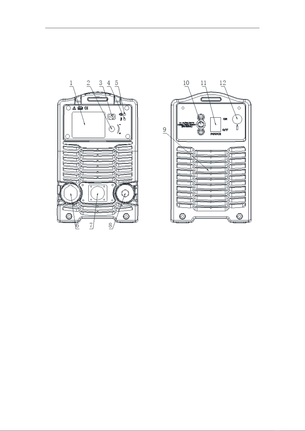
HTP MicroCut 45 DV User manual

HTP America, Inc. · 180 Joey Drive · Elk Grove Village, IL 60007-1304
Phone: 847-357-0700 · Fax: 847-357-0744 · Web: www.usaweld.com
IMPORTANT: Read this Owner’s Manual Completely before attempting to use this
equipment. Save this manual and keep it handy for quick reference. Pay particular
attention to the safety instructions we have provided for your protection. Contact your
distributor if you do not fully understand this manual.
HTP MicroCut 45 DV
OPERATOR’S MANUAL

I

I
General Information
Thank you and congratulations on purchasing an HTP MicroCut 45DV. With many
welding and cutting equipment options available on the market today, we appreciate your
purchase, as well as the confidence you put into HTP through purchasing one of our
products.
The versatile MicroCut 45DV works as a manual cutter and/or with a CNC plasma cutting
table. The HTP MicroCut 45DV has a dedicated CNC mode. In order to use this as a CNC
cutter you will need to purchase the CNC torch. You can also operate the MicroCut 45 DV
manually with a 20’ hand torch. If you purchased the 20’ hand torch, you can always
upgrade your machine to meet CNC plasma cutting table compatibility at a later date. As
an added bonus, the hand torch and machine torch utilize the same consumables, apart
from the shield cap, so you only need to keep on-hand a single style of replacement parts.
We hope you enjoy working with your new plasma cutting machine! If, at any time, you
need help setting up or operating your plasma cutter, at any time, please feel free to contact
us: 847-357-0700
Manufacturer’s Warranty
Subject to the terms and conditions hereof, HTP warrants that all MicroCut 45 DV plasma
cutters furnished by HTP are free from defects in workmanship and material as of the time
and place of delivery by HTP. No warranty is made by HTP with respect to trade
accessories or other items manufactured by others. Such trade accessories and other items
are subject to the warranties, if any, of their respective manufacturers only.
HTP shall be required to honor warranty claims on MicroCut 45 DV plasma cutters in the
event of a failure resulting from a defect. Please reference the warranty chart below to see
the warranty period. The warranty starts at the time of delivery of the MicroCut 45 DV to
the original owner, you must notify HTP in writing within thirty (30) days of the date of
failure:
1) Plasma cutters, power sources, and components:
2 Years
2) Plasma torches:
90 Days
3) The shield cap, shield cup body, cutting tip, electrode, and swirl ring are consumable
items and CARRY NO WARRANTY.
As a matter of general policy only, HTP may honor claims submitted by the original owner
within the above times.
In the case of HTP’s breach of warranty or any other duty with respect to the quality of any
goods, the exclusive remedies therefore shall be, at HTP’s option, (1) repair or (2)

I
replacement or, where authorized in writing by HTP in appropriate cases, (3) the
reasonable cost of repair or replacement at an authorized HTP service station upon return
of the goods at the Customer’s risk and expense. HTP’s option of repair or replacement
will be F.O.B., to the factory in Elk Grove Village, Illinois, therefore, no compensation for
transportation costs of any kind will be allowed. Upon receipt of notice of apparent defect
or failure, HTP shall instruct the claimant on the warranty claim procedures to be followed.
HTP America, Inc. has reserved the right to make changes in design or add any
improvements to its products at any time without incurring any obligation to install the
same on previously purchased equipment.
This warranty is null and void unless the warranty registration is sent to HTP America, Inc.
within fifteen (15) business days from the date of purchase.
Any express warranty not provided herein and any implied warranty, guarantee or
representations as to performance, and any remedy for breach of contract which, but for
this provision, might arise by implication, operation of law, custom of trade or course of
dealing, including any implied warranty of merchantability or of fitness for particular
purpose, with respect to any and all equipment furnished by HTP is excluded and
disclaimed by HTP.
Note: This warranty is to the original purchaser only. The warranty can be transferred to
another owner for a $25 warranty transfer fee. HTP must be notified within fourteen (14)
days of the sale and must be provided with the contact info of the original owner and the
contact info of the new owner.

I
Index
1 SAFETY.................................................................................................................................................1
2 PARAMETERS.....................................................................................................................................3
2.1 PARAMETERS ........................................................................................................................................... 3
3 INSTALLATION ..................................................................................................................................4
3. 1 UNPACKING ............................................................................................................................................. 4
3.2 INPUT POWER CONNECTIONS ................................................................................................................... 4
3. 3 AIR CONNECTIONS .................................................................................................................................. 4
4 OPERATION.........................................................................................................................................4
4.1 LAYOUT OF THE FRONT AND REAR PANEL.............................................................................................. 5
4.2 FUNCTION INTRODUCTION........................................................................................................................ 6
4.3 CUTTING PREPARATION............................................................................................................................ 9
4.4 CUTTING OPERATION ............................................................................................................................. 10
5 MAINTENANCE................................................................................................................................11
5.1 CUTTING TORCH MAINTENANCE ..............................................................................................................11
5.2 TROUBLESHOOTING PRINCIPLE .............................................................................................................. 12
6 CUTTING GUIDELINES…………………………………………………………………………...14
7 CONSUMABLE BREAKDOWNS………………………………………………………………….15
8 APPENDIX……………………………………………………………………………………………16

1
1.Safety
Important Safety Precautions
OPERATION AND MAINTENANCE OF PLASMA EQUIPMENT CAN BE DANGEROUS
AND HAZARDOUS TO YOUR HEALTH.
Plasma cutting produces intense electric and magnetic emissions that may interfere with the proper
function of cardiac pacemakers, hearing aids, or other electronic health equipment. Persons who work
near plasma cutting applications should consult their medical health professional and the manufacturer
of the health equipment to determine whether a hazard exists. To prevent possible injury;read,
understand, and follow all warnings, safety precautions and instructions before using the equipment.
GASES AND FUMES
Gases and fumes produced during the plasma cutting process can be dangerous and hazardous to your
health.
• Keep all fumes and gases from the breathing area. Keep your head out of the cutting fume plume.
• Use an air-supplied respirator if ventilation is not adequate to remove all fumes and gases.
• The kinds of fumes and gases from the plasma arc depend on the kind of metal being used, coatings
on the metal, and the different processes. You must be very careful when cutting any metals which may
contain one or more of the following:
Antimo
ny
Chromiu
m
Mercury
Berylliu
m
Arsenic
Cobalt
Nickel
Lead
Barium
Copper
Seleniu
m
Silver
Cadmiu
m
Manganes
e
Vanadiu
m
Always read the Material Safety Data Sheets (MSDS) that should be supplied with the material you are
using. These MSDSs will give you the information regarding the kind and amount of fumes and gases
that may be dangerous to your health.
• Use special equipment, such as water or down draft cutting tables, to capture fumes and gases.
• Do not use the plasma torch in an area where combustible/explosive gases or materials are located.
• Phosgene, a toxic gas, is generated from the vapors of chlorinated solvents and cleansers. Remove all
sources of these vapors.
ELECTRIC SHOCK
Electric Shock can injure or kill. The plasma process uses and produces high voltage electrical energy.
This electric energy can cause severe or fatal shock to the operator or others in the workplace.
• Never touch any parts that are electrically “live” or “hot.”
• Wear dry gloves and clothing. Insulate yourself from the work piece or other parts of the cutting

2
circuit.
• Repair or replace all worn or damaged parts.
• Extra care must be taken when the workplace is moist or damp.
• Disconnect power source before performing any service or repairs.
• Read and follow all the instructions in the Operating Manual.
FIRE AND EXPLOSION
Fire and explosion can be caused by hot slag, sparks, or the plasma arc.
• Be sure there is no combustible or flammable material in the workplace. Any material that cannot be
removed must be protected.
• Ventilate all flammable or explosive vapors from the workplace.
• Do not cut or weld on containers that may have held combustibles.
• Provide a fire watch when working in an area where fire hazards may exist.
• Hydrogen gas may be formed and trapped under aluminum workpieces when they are cut underwater
or while using a water table. DO NOT cut aluminum alloys underwater or on a water table unless the
hydrogen gas can be eliminated or dissipated. Trapped hydrogen gas that is ignited will cause an
explosion.
NOISE
Noise can cause permanent hearing loss. Plasma processes can cause noise levels to exceed safe limits.
You must protect your ears from loud noise to prevent permanent loss of hearing.
• To protect your hearing from loud noise, wear protective ear plugs and/or ear muffs. Protect others in
the workplace.
• Noise levels should be measured to be sure the decibels (sound) do not exceed safe levels.
PLASMAARC RAYS
Plasma Arc Rays can injure your eyes and burn your skin. The plasma arc process produces very bright
ultra violet and infra-red light. These arc rays will damage your eyes and burn your skin if you are not
properly protected.
• To protect your eyes, always wear a cutting helmet or shield. Also,always wear safety glasses with
side shields, goggles or other protective eye wear.
• Wear cutting gloves and suitable clothing to protect your skin from the arc rays and sparks.
• Keep helmet and safety glasses in good condition. Replace lenses when cracked, chipped or dirty.
• Protect others in the work area from the arc rays. Use protective booths, screens or shields.

3
2. Parameters
2.1 Parameters
Models
Parameters
MicroCut45DV
Normal/Grid
Gouge
Input power
1-120/230V,50/60Hz
1-120V
1-230V
1-120V
1-230V
Rated input current(A)
38
33
20.9
20.6
Rated input power(KW)
4.47
7.03
2.30
6.18
Adjustment range of current(A)
20~25
20~45
10~25
10~45
Max no-load voltage(V)
230
Duty cycle: (40℃,10 minutes)
40%
25A145V
50%
45A145V
40%
25A110V
50%
45A118V
Note: The above parameters are subject to change with the improvement of machines.
Maximum permissible system impedance 0.387Ω.
Generator Information:
When operating on a generator you will need to have 9500 continuous or running watts.

4
3.Installation
3.1 Unpacking
1. Use the packing lists to identify and account for each item.
2. Inspect each item for possible shipping damage. If damage is evident, contact HTP
before proceeding with the installation.
3.2 Input Power Connections
Note: Check your power source for correct voltage before plugging in or connecting
the unit.
3.3 Air Connections
A. Connecting Air Supply to Unit
Connect the air line to the inlet port of the air filter on the rear panel.
B. Check Air Quality
To test the quality of air, press on the function button briefly and hold the torch head
near a paper towel or clean surface. Check if there is any oil or moisture residue on the
clean surface when the air is coming out of the torch.

5
4.Operation
4.1 Layout Of The Front And Rear Panel
Figure 1.
1. LCD - Display machine status, such as the cutting current, air pressure, cutting
mode, etc
2. Encoder - Adjust the cutting current and air pressure
3. Function Button - Select cutting mode, switch between first and second menu.
4. Over-Heat Alarm - When over-heating, the yellow light will be on.
5. Power Light – A solid green light indicates the power is on.
6. Cutting Torch Connector
7. Torch Central Connector
8. Positive Output For GROUND Cable
9. Fan
10. Power Cable - Connected to the appreciate power supply
11. Power Switch - Turn on or off the power source
12. Compressed Air Connector

6
○
8
4.2 Function Introduction
○
1 ○
2 ○
3
Figure 2.
① Check whether the cutting torch is connected
② Air pressure light
③ The machine is in working condition
④ Grid cutting mode
⑤ Normal cutting mode
⑥ Gouging/marking cutting mode
⑦ The types of the cutting torch
⑧ Transfer arc/ Arc OK signal
⑨ Cutting parameters which contains air pressure/output voltage/ the recommended
length of the cutting torch
⑩ Cutting current
Tips: The LCD contains two menus. In the first menu, the cutting current and
the cutting mode can be adjusted. To get to second menu, hold down the function
button for 1 second, the cutting parameters flashes. Now it is on the second menu.
If there is no operation for 6 seconds, hold down the function button for 1 second
again, the cutting current display flashes, it will switch back to first menu.
○
6
○
4
○
5
○
9
○
10
○
7

7
1.Cutting mode selection
2. Cutting parameters (which contains air pressure/output voltage/ the recommended
length of the cutting torch) Hold down the function button for 1 second, the cutting
parameters flashes, then you can adjust the air pressure. Press on the function button
briefly to set Bar, Mpa or Psi. Continue to press on function button briefly, the output
voltage and the recommended length of the cutting torch will display as shown in the
Figure 6 and 7. Figure 6 shows the arc voltage and that the arc is on. Figure 7 shows
the torch length in meters, arc is not on.
Figure 3. Figure 4. Figure 5.
Figure 6. Figure 7.
Grid cutting mode: use the encoder to adjust the cutting
current, press on the function button briefly to switch cutting
mode.
The current range is 20-45A, the air pressure range is 4.2-
5.6Bar.
Normal cutting mode, use the encoder to adjust the cutting
current, press on function button briefly to switch cutting
mode.
The current range is 20-45A, the air pressure range is 4.2-
5.6Bar.
Gouging/marking cutting mode, use the encoder to adjust the
cutting current, press on function button briefly to switch
operational mode. The current range is 10-45A. When the
current is between 20A and 45A, the cutting mode is
gouging, the air pressure range is 2.1-3.5 Bar. When the
current is between 10A and 20A, the cutting mode is
marking, the air pressure range is 2.1-3.1Bar.

8
3.Two different kinds of cutting torches
Figure 8. Hand Torch Figure 9. Machine Torch
4. Alarm display

9
Light
Condition
Display
Status/Possible Cause
E01
Over-Current- Check output
diodes, main transformer and
IGBT on the invert board.
Temp
On
E02
Over-Temperature- Stop
cutting, allow machine to
cool down.
E03
No system is established-
Check output diodes, main
transformer and IGBT on the
invert board.
Nozzle
Repetative flashing rate of 3
quick circles, then a 1 second
pause for a 15 second period or
until torch trigger is pressed
again, whichever comes first.
E04
No pilot arc established
possibly due to a loss of
current- Check consumables.
Nozzle
Repetative flashing rate of 3
quick circles, then a 1 second
pause for a 15 second period or
until torch trigger is pressed
again, whichever comes first.
E05
Consumables in torch failed
to separate during pilot arc
possibly due to being stuck-
Check consumables.
E09
No input power.
Cup &
Nozzle
Repetative flashing rate of one
quick circle.
E11
Torch cup is loose or off.
Pressure
Repetative flashing rate of 1
quick circle.
E13
E13 means air pressure is out
of range. H means air
pressure has exceeded setting
range. L means air pressure is
under setting range.In
Normal/Grid,the setting
range of air pressure is 4.2-
5.6bar. In Gouging,the
setting range of air pressure
is 2.1-3.5bar. In Marking,the
setting range of air pressure
is 2.1-3.1bar.

10
4.3Cutting Preparation
1. Tightly connect the power cable to electrical socket outlet (the input voltage,
refer to the section 2. technology parameters)
2. Connect the air line to the air supply equipment, and the ground cable to the
workpiece.
3. Turn on the power switch. The power source light will be green when turned on.
4. Regulate the current after the fan stops.
4.4Cutting Operation
Note:
1. If alarm light is on when cutting, you will need to let go of the trigger on the torch
until the alarm releases. Then press on the trigger to start cutting again.
2. In the automatic air test the machine will read the target air pressure in idle. To adjust
air pressure, press and realease the trigger so air stats flowing. Open the side door of
cabinate to adjust the air presure.
3. After using the machine for a longer period of time, the surface of the electrode and
nozzle will have an Oxidation reaction. Please make sure to replace the electrode and
nozzle. The alarm light will go on and the machine will stop working when it is time to
install a new shield cup.
Pull trigger
Turn on
the power
source
Air flows for 5 seconds,
check display to verify
pressure. Make
adjustments as needed
Pilot arc
ignites
the cutting arc
changes into
pilot arc again
Attach ground
clamp to
workpiece
shift to the workpiece,
the pilot arc changes
into the cutting arc
the torch
leaves the
workpiece,
Arc
extinguishes
grid/gouging /marking
Release Trigger
Post-air
flow
normal

11
5.Maintenance
5.1 Cutting Torch Maintenance
Warning :
1. Check the consumable parts for damage, if worn, make sure you replace the
comsubales.
2. Turn off the power source before checking or removing cutting torch parts.
Note: When operating the torch in a normal condition, a small amount of air vents
through the gap between the shield cup and the torch handle, Do not attempt to over
tighten the shield cup as irreparable damage to internal components may result.
Socket
1. Torch switch.
2. Common.
3. Machine/Manual torch.
4. Torch length.
5. Pilot arc cable.
6. Pilot arc cable.
8. Common.
9. Torch shield cable.
Function
Connection method
Torch switch
1.2
Machine torch
3.2
Manual torch
Torch length
4.2
Pilot arc
5.6
Torch shield
8.9

12
5.2 Troubleshooting Principle
WARNING
There are extremely dangerous voltage and power levels present inside this unit.
Do not attempt to diagnose or repair unless you have had training in power
electronics measurement and troubleshooting techniques.
A. Temperature light on.
1. Fan blocked, check and correct condition.
2. Unit is overheated, let unit cool down for at least 5 minutes. Make sure the unit has
not been operated beyond Duty Cycle limit, refer to technology parameters in Section
2.
3. Faulty components in unit, return for repair.
B. Torch fails to ignite the arc when trigger is pulled
1. Faulty torch parts, inspect torch parts and replace if necessary.
2. Air pressure too high or too low, adjust to proper pressure.
3. Faulty components in unit, return for repair.
C. No cutting output; trigger pulled, power source on; air flows; fan operates
1. Torch not properly connected to power supply, check that torch leads are properly
connected to power supply.
2. Ground clamp not connected to work piece, or connection is poor, make sure that
the ground cable has a proper connection to a clean, dry area of the workpiece.
3. Faulty components in unit, return for repair or have qualified technician repair.
4. Faulty Torch, return for repair or have qualified technician repair.
D. Low cutting output
1. Incorrect setting of CURRENT (A) control, check and adjust to proper setting.
2. Faulty components in unit, return for repair or have qualified technician repair.

13
E. Difficulty Starting
1. Worn torch parts (consumables), make sure to turn off the machine before checking
the consumables. Remove and inspect torch shield cup, tip and electrode. Replace
electrode or tip if worn; replace shield cup if there is excessive spatter adhering to it.
F. Arc shuts off during operation; arc will not restart when trigger is pulled
1. Power Supply is overheated (OT light on), let unit cool down for at least 5 minutes.
Make sure the unit has not been operated beyond Duty Cycle limit. Refer to Section 2
for duty cycle specifications.
2. Air pressure is out of range; adjust as needed.
3. Torch consumables worn, check torch shield cup, tip, starter element, and electrode;
replace as needed.
4. Faulty components in unit: return for repair or have qualified technician repair.
G. No air flows; the power light is on; Fan operates
1. Air is not connected or pressure is too low, please check your air connections.
Adjust air pressure to proper setting.
2. Faulty components in unit, return for repair or have qualified technician repair.
H. Torch cuts but low quality
1. Current (A) control set too low, increase current setting.
2. Torch is being moved too fast across workpiece, reduce cutting speed.
3. Excessive oil or moisture in torch, hold torch 1/8 inch (3 mm) from clean surface
while purging the air line. Observe if there is an oil or moisture build up on the clean
surface (do not activate torch). If there are contaminants in the air, additional filtering
may be needed.

14
6. Cutting Guidelines

15
7. Consumable Breakdowns
Consumable Parts Breakdown –Hand Torch
Consumable Parts Breakdown- Machine Torch
Table of contents
Other HTP Welding System manuals

HTP
HTP MTS 210 User manual

HTP
HTP Pro Pulse 200 User manual

HTP
HTP Invertig 301 User manual

HTP
HTP Invertig 313 User manual

HTP
HTP Invertig 200 User manual

HTP
HTP Revolution 2500 User manual

HTP
HTP Inverarc 200 TLP User manual

HTP
HTP MTS 160 User manual

HTP
HTP MIG 130 User manual

HTP
HTP InverArc 160 Plus User manual

HTP
HTP Pro Pulse 220 MTS User manual

HTP
HTP Invertig 201 AC/DC User manual

HTP
HTP Quick Spot II User manual

HTP
HTP MicroCut 875SC User manual

HTP
HTP MIG 2400 User manual

HTP
HTP MICROCUT 600 User manual

HTP
HTP Invertig 221 AC/DC User manual

HTP
HTP MIG 200i User manual

HTP
HTP Invertig 160DC User manual

HTP
HTP Pro Pulse 300 User manual