Huaray Movidius Series User manual

Smart Industrial Camera
User’s Manual
V 1.0.0

I
Foreword
Overview
This document briefly describes GigE smart industrial camera, including product introduction,
networking, basic parameter and quick operation of application software.
Symbol Definition
The following symbols may appear in this document.And their meanings are as follows:
Symbol
Note
It indicates a potentially hazardous situation which, if not avoided, could
result in death or serious injury.
It indicates a moderate or low level of potential danger which, if not
avoided, could result in minor or moderate injury.
It indicates a potential risk that, if ignored, could result in damage to
device, loss of data, degraded performance, or unpredictable results.
It means electrostatic-sensitive device.
It means high-voltage danger.
It means intensive laser radiation.
It means that it can help you to solve some problems or save your time.
It means the additional information, which is to emphasis or
supplement.

II
Important Safeguards and Warnings
The following description is the correct application method of the device. Please read the
manual carefully before use, in order to prevent danger and property loss. Strictly conform to
the manual during application and keep it properly after reading.
Please don’t place and install the device in an area exposed to direct sunlight or near heat
generating device. Ensure that shell temperature is below 60°.
Please don’t install the device in a humid, dusty or fuliginous area. If the lens is not
connected, please put on the lens cap, in order to prevent dust.
Please install it stably, and prevent it from falling.
Please don’t drip or splash liquids onto the device; don’t put on the device anything filled
with liquids, in order to prevent liquids from flowing into the device.
Please install the device at well-ventilated places; don’t block its ventilation opening.
Use the device only within rated input and output range.
Please don’t dismantle the device arbitrarily.
Please transport, use and store the device within allowed humidity and temperature range.
Products with category I structure shall be connected to grid power output socket, which is
equipped with protective grounding.
About this Document
This document is for reference only. Please refer to the actual product for more details.
This document serves as a reference for multiple types of products, whose specific
operations won’t be enumerated. Please operate according to actual products.
The user shall undertake any losses resulting from violation of guidance in the document.
In case that PDF document cannot be opened, please upgrade the reading tool to the
latest version or use other mainstream reading tools.
This company reserves rights to revise any information in the document anytime; and the
revised contents will be added to the new version without prior announcement. Some
functions of the products may be slightly different before and after revision.
The document may include technically inaccurate contents, inconsistencies with product
functions and operations, or misprint. Final explanations of the company shall prevail.

III
Table of Contents
Foreword..................................................................................................................................................................I
Important Safeguards and Warnings..............................................................................................................II
Table of Contents................................................................................................................................................III
1Product Overview.............................................................................................................................................. 1
1.1 Product Introduction ................................................................................................................................. 1
1.2 Product Feature......................................................................................................................................... 1
1.3 Packing List................................................................................................................................................ 1
1.4 Product Structure...................................................................................................................................... 2
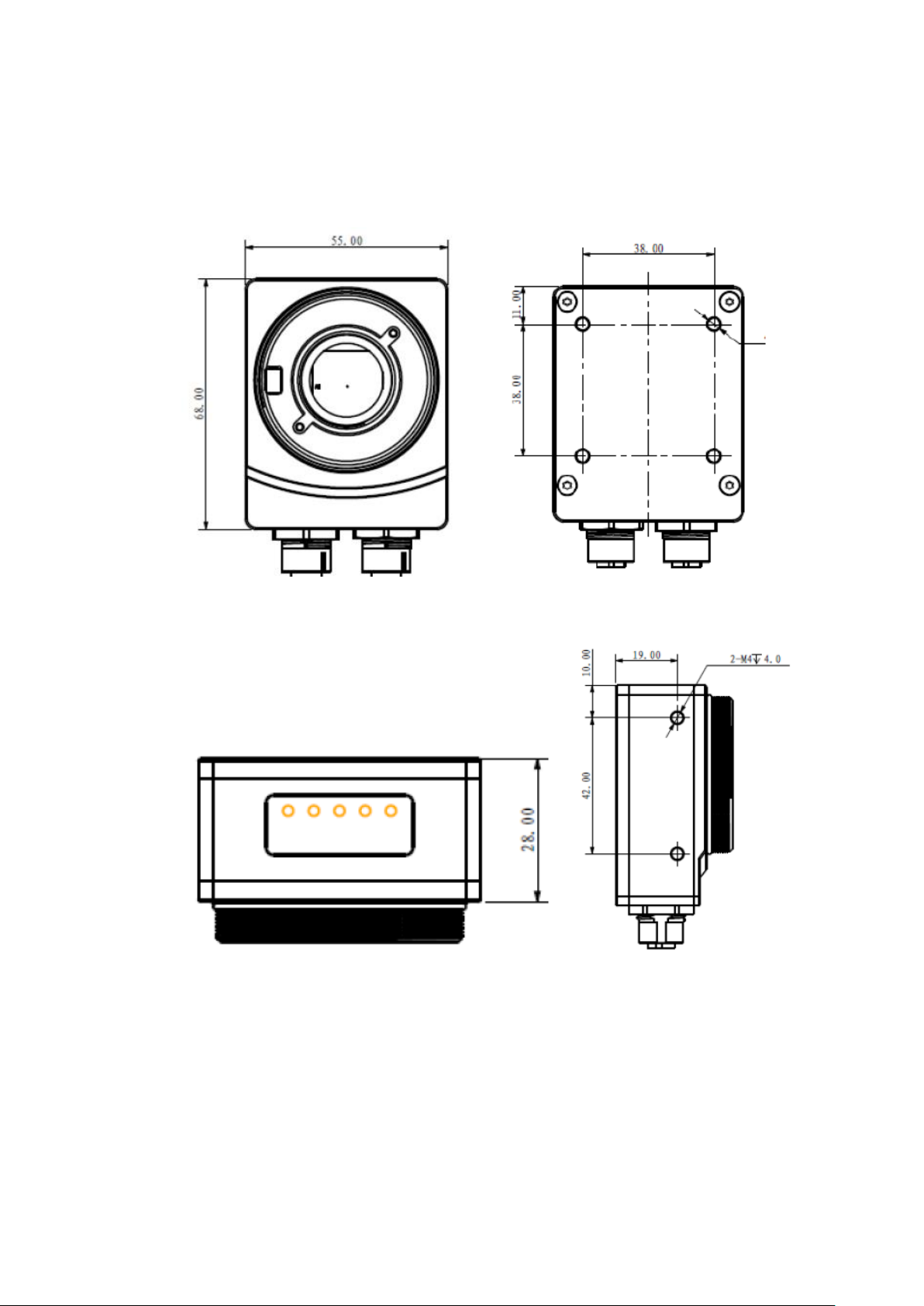
1.4.1 Product Dimension........................................................................................................................ 2
1.4.2 Interface Description..................................................................................................................... 2
8-pin Network Interface.......................................................................................................................... 3
12-pin Power and I/O Interface............................................................................................................. 3
1.5 Electric Specification................................................................................................................................. 4
1.5.1 Electric Specification of Power and Network Interface............................................................ 4
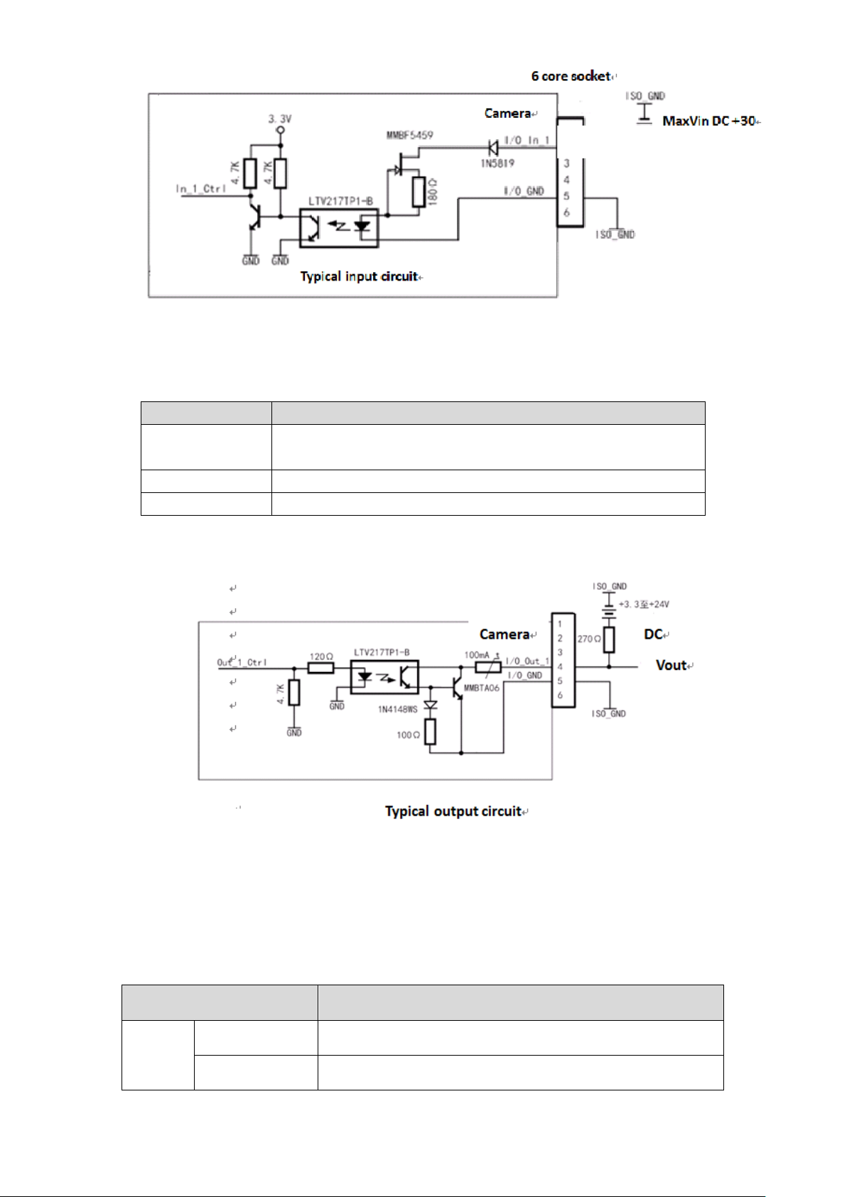
1.5.2 Electric Specification of IO Interface.......................................................................................... 4
1.6 Indicator Light Description....................................................................................................................... 5
1.7 Environmental Requirement.................................................................................................................... 6
2Typical Networking......................................................................................................................................... 7
3Product Installation........................................................................................................................................... 8
3.1 Hardware Installation................................................................................................................................ 8
3.1.1 Camera Installation....................................................................................................................... 8
3.2 App Installation.......................................................................................................................................... 9
4Setting of Smart Camera................................................................................................................................ 12
4.1 Config Wizard.......................................................................................................................................... 12
4.2 Disconnect and Connect Camera ........................................................................................................ 14
4.3 Image Setting .......................................................................................................................................... 16
4.4 Vision Setting........................................................................................................................................... 19
4.5 Communication Setting.......................................................................................................................... 21
4.6 IO Control Setting ................................................................................................................................... 24
4.7 Config Management............................................................................................................................... 26
4.8 Vision Mode Operation........................................................................................................................... 26
4.8.1 Vision Mode................................................................................................................................. 26
4.8.2 Image Display.............................................................................................................................. 27
4.8.3 Result............................................................................................................................................ 27
4.9 Save Images............................................................................................................................................ 28
5Main Functions................................................................................................................................................. 29
5.1 Device Info............................................................................................................................................... 29
5.2 Image Setting .......................................................................................................................................... 30
5.2.1 Exposure...................................................................................................................................... 30
5.2.2 Focus............................................................................................................................................ 31

IV
5.2.3 Trigger........................................................................................................................................... 32
5.2.4 ISP................................................................................................................................................. 33
5.3 Vision Setting........................................................................................................................................... 35
5.3.1 Bar Code...................................................................................................................................... 35
5.3.2 QR Code....................................................................................................................................... 37
5.4 Communication Setting.......................................................................................................................... 39
5.4.1 Transport Layer Control ............................................................................................................. 39
5.4.2 Result Transfer Control.............................................................................................................. 40
5.4.3 Ethernet Transfer Control........................................................................................................... 42
5.5 I/O Control Setting.................................................................................................................................. 44
5.5.1 Input Control Setting................................................................................................................... 44
5.5.2 Output Control Setting................................................................................................................ 45
5.5.3 Beeper.......................................................................................................................................... 46
5.5.4 LED ............................................................................................................................................... 47
5.5.5 Light............................................................................................................................................... 48
5.6 Config Management............................................................................................................................... 48
5.7 Device Params........................................................................................................................................ 49
6FAQ...................................................................................................................................................................... 51
7Cleaning and Maintenance............................................................................................................................ 53

1
1Product Overview
1.1 Product Introduction
This product uses high-performance sensor chip. Max transmission rate of 1Gb/s can satisfy
the requirements of transmission rate in most industrial applications. It can work in various
harsh environments stably with high reliability and cost performance.
1.2 Product Feature
With easy installation and convenient operation,
With GigE port, max transmission distance can be up to 100m.
512MB memory and 512MB non-volatile flash memory.
Support software trigger/external trigger/free run mode.
Abundant I/O interfaces, including RS232, 3-channel opto-isolated inputs and 3-channel
opto-isolated outputs.
Support lens equipped with C and M12 mounts, and optional built-in optical source.
Industrial M12 connector.
Support DC8~26V wide-range power supply; suitable for different industrial DC12/24V
voltage environment.
Abundant algorithm tools for code recognition, template matching and positioning.
Conform to CE, FCC and RoHS certifications.
1.3 Packing List
When unpacking the outer packing box, please check whether the device shows obvious
damages, and confirm whether accessories are consistent with the packing list. For details,
please refer to Table 1-1.
Packing List
1
Smart industrial camera
1
2
M4×10 screw
4
Table 1-1

2
1.4 Product Structure
1.4.1 Product Dimension
Please refer to Figure 1-1 for product dimension.
Figure 1-1 Product Dimension (55mm×68mm×28mm, unit: mm)
1.4.2 Interface Description
At the bottom of the device, there are an 8-pin network interface and a 12-pin power & I/O
interface, as shown in 错误!未找到引用源。.

3
Figure 1-2
8-pin Network Interface
8-pin network interface, which converts M12 to RJ45, is Ethernet transmission interface allowing
10M/100M/1000M bps transmission rate. It is used for camera control and data transmission.
To guarantee transmission quality, it is suggested that shielded twisted pair CAT 6 network cable
should be used, in order to prevent excessive data retransmission and data packet dropout.
12-pin Power and I/O Interface
For pin signal definition of 12-pin power and I/O port, please refer to Table 1-2.
Pin
Color
Signal
Note
1
Yellow
OPT_IN1
Opto-isolated input 1
2
Yellow and white
OPT_IN2
Opto-isolated input 2
3
Brown
OPT_OUT1
Opto-isolated output 1
4
Brown and white
OPT_OUT2
Opto-isolated output 2
5
Purple
RXD RS232
Serial port reception
6
Purple and white
OPT_IN_GND
Opto-isolated input ground
7
Red
Power
Power
8
Black
Power Ground
Power ground
9
Green
OPT_OUT_GND
Opto-isolated output ground
10
Orange
OPT_IN0
Opto-isolated input 0
11
Blue
OPT_OUT0
Opto-isolated output 0
12
Gray
TXD RS232
Serial port transmission
Shielded
Braided
Shielded GND
SGND
(Black sleeve)

4
Table 1-2
1.5 Electric Specification
1.5.1 Electric Specification of Power and Network Interface
Parameter
Note
Camera power
DC +8V~+26V, <1% ripple, supply power via 12-core M12 connector1;
At least 26AWG cable.
EMS standard
Electrostatic discharge (GBT17626.2/IEC61000-4-2)
Contact of metal shell: 6kV
Surge (IEC61000-4-5)
Power interface: 1kV common mode (1.2/50us)
EMC standard
Class B
Table 1-3
1. Power supply shall conform to SELV and LPS specification.
1.5.2 Electric Specification of IO Interface
1.5.2.1 Opto-isolated Input
Input Voltage
Description
DC 26V
It is the limit voltage. The input cannot exceed this limit value;
otherwise the device will be damaged.
DC 0~24V
Safe working range of I/O input.
DC 0~1.4V
It represents logic 0.
DC >1.4V~2.2V
Turn over the input status here. Logic status is indefinite within this
voltage range.
DC >2.2V
It represents logic 1.
Table 1-4
Sink current of isolated I/O input interface is 5mA~15mA.

5
Figure 1-3
1.5.2.2 Opto-isolated Output
Voltage
Description
DC 26V
It is the limit voltage. The input cannot exceed this limit value;
otherwise the device will be damaged.
DC <3.3V
I/O output may have an error.
DC 3.3V~+24V
Safe voltage range of I/O output.
Table 1-5
Maximum 50mA current passes isolated I/O output continuously.
Figure 1-4
1.6 Indicator Light Description
For indicator light description of GigE area scan industrial camera, please refer to Table 1-6.
Indicator Light Status
Description
SYS
On
Normal power-on camera.
Off
Abnormal power-on camera or abnormal indicator light.

6
NET
On
Normal network connection.
Off
Abnormal network connection or abnormal indicator light.
TRIG
On (or
flickering)
Images are captured, including free run mode.
In condition of high frame rate or trigger frequency, it is
approximately normally on.
In condition of low frame rate or trigger frequency, it
flickers.
Off
No image is captured or abnormal indicator light.
USR0
Indicator light for user mode, to be customized.
USR1
Indicator light for user mode, to be customized.
Table 1-6
1.7 Environmental Requirement
Environmental requirement of the camera is as follows:
Temperature and humidity
Environmental temperature shall not exceed 50℃; air-conditioned environment is preferred.
Working case temperature: 0℃~60℃.
Working environmental humidity: 20%~80%, no condensation.
Storage temperature: -30℃~+80℃.
Storage humidity: 20%~80%, no condensation.
The device is installed indoors stably, with sufficient heat dissipation space all around.
Ensure certain air flow.

7
2Typical Networking
The most typical networking mode is point-to-point connection, which needs no other network
medium between the host computer and industrial camera. Please refer to Figure 2-1.
After connection, client installed in PC can detect online camera, add PC and camera to the
same network segment and operate the camera.
Figure 2-1

8
3Product Installation
It mainly consists of hardware installation and App installation.
3.1 Hardware Installation
Before installation, please check whether the device shows obvious damages, and confirm
whether accessories are consistent with the packing list.
3.1.1 Camera Installation
During installation, please consider electrostatic, electromagnetic interference, lightning stroke
and surge, as well as heat dissipation of the camera.
3.1.1.1 Electrostatic, Electromagnetic Interference, Lightning Stroke and
Surge Protection Consideration
Although the camera boasts inside anti-thunder, anti-surge and EMI (electromagnetic
interference) and ESD (electrostatic discharge) protection design, for the sake of safety, these
impacts shall be avoided or reduced with installation environment and installation mode.
The following protection methods are recommended:
Adopt SSTP shielded network cable. As long as it meets use requirement, don’t place
excessively high requirements on flexibility of network cable. To reach good flexibility,
copper wire, shielded aluminum foil thickness, shielding net density and PVC sleeve
performance are reduced.
Network cable shall be as short as possible. In case of too long and redundant network
cable, adopt serpentine wiring, rather than putting it in circles, in order to reduce
electromagnetic interference coupling.
Power control cable shall use shielded cable, and avoid circles. Power cable and network
cable can be parallel but avoid twisting.
Power cable and network cable shall keep away from equipment with large current, high
voltage, or frequent reboot and shutdown operations, such as stepping motor. In particular,
avoid parallel wiring with this type of device, whose strong electromagnetic radiation easily
couples to transmission cable of the camera.
Protective ground wire of all devices shall be connected with protective ground wire at
single point; avoid multi-point grounding, since multi-point grounding easily leads to
voltage difference between devices, and forms a loop that couples electromagnetic
interference.
AC ends on switching power supply for the camera and power supply of PC shall come

9
from the same AC extension socket, so their protective ground wires are connected
together, in order to avoid multi-point grounding. High-power electromechanical device
shall not use the AC power directly.
Add a magnet ring to power control cable of the camera, to absorb electromagnetic
interference signals.
Ensure certain ambient humidity, put on antistatic wrist strap, clothes and shoes during
operation, and thus reduce ESD.
3.1.1.2 Heat Dissipation Consideration
Under the condition of relatively stable ambient condition (temperature, humidity, airflow and
installation position etc.) for about 1 hour~1.5 hours, the camera reaches temperature
equilibrium. That is to say, case temperature won’t rise any more. But please ensure case
temperature doesn’t exceed 50℃under the thermos-stabilization status; because there is 25℃
temperature difference between internal main heat source and the case, internal electronic chip
will not be damaged when the case temperature is below 50℃.
The following methods are recommended to control temperature:
Ambient temperature doesn’t exceed 30℃; air-conditioned environment is preferred.
Install the device on a material with good thermal conductivity, such as metal. Metal area
shall be large enough to dissipate the heat.
Ensure certain airflow, for the purpose of better heat dissipation.
3.2 App Installation
App installation steps are as follows:
Step 1 Open PC.
Step 2 Install MV Viewer client.
Double click the client installation package and operate according to the prompt on the
interface. You can see Figure 3-1 after installation.
If patches have not been installed, please install patches first, and then install MV
Viewer client software.

10
Figure 3-1
Step 3 Double click the client installation package and operate according to the prompt on the
interface to install SVStudio. You can see 错误!未找到引用源。after installation.
Please contact technical support personnel to obtain App installation package.

11
Figure 3-2

12
4Setting of Smart Camera
Please ensure that GigE smart camera and PC are connected correctly.
Install App in PC. Please refer to “3.2 App Installation” for details.
After wiring, App in the PC is able to detect online camera. The camera works normally as long
as the camera IP and local computer IP are in the same network segment. For specific
parameter configurations of smart camera, please operate according to this chapter.
4.1 Config Wizard
Double click desktop shortcut to open App software. The software detects all online
devices automatically, as shown in Figure 4-1.
Figure 4-1

13
After SVStudio is started, config wizard interface is displayed on the left. Press page up and
page down buttons to carry out camera connection, image setting, vision setting and so on.
Camera detection scene is displayed directly in the image play interface at the upper right
corner, while detection result interface at the lower right corner displays receive time, detect
time, status, type and result.
Click , and the interface is shown in Figure 4-2.
Figure 4-2
With toolbar buttons as shown in Figure 4-3, find a config quickly. Table 4-1 describes menu bar
items and functions.
Figure 4-3
Menu
Description
Home
Config
Camera
connection
Connect or disconnect the camera; modify camera IP
configuration.
Image setting
Configure image exposure, trigger and ISP
parameters.
Vision setting
Configure bar codes and QR codes to be measured.
Communication
setting
Configure parameters of transport layer control, result
transport control and Ethernet transport control.
IO control setting
Configure parameters of input, output, buzzer, LED
and optical source.

14
Menu
Description
Config
management
Save parameters that are configured by the user.
Run
Preview mode
Adjust the camera to this mode, click to preview
video, configure image parameter to the best
performance and switch to vision mode.
Under this mode, the camera cannot read codes.
Vision mode
Read the bar codes and QR codes. The camera
mainly works under this mode.
Save images
Choose to save images continuously or not. Choose
directory and image format.
Images can be saved in JPEG, BMP and raw binary
format.
File
Import
Import camera configuration info from the host.
Export
Export camera configuration info to the host.
Help
Config wizard
The camera skips to configuration wizard, so it can be
configured according to the wizard.
Language
Language includes:
Chinese;
English;
Device params
View and modify all configuration parameters of
current device.
User manual
View user manual of current software.
About
View version info of current software.
View
Window
Config
Choose to display configuration window or not.
Image
Choose to display image window or not.
Result
Choose to display result window or not.
Table 4-1
4.2 Disconnect and Connect Camera
After start, camera connection interface discovers cameras in the same network segment and
displays them in “Device List”. If a new smart industrial camera is added, click “Refresh”button
to refresh the device list.
Move the mouse to the device that will be connected, click “Connect”button or double click the
item to connect the camera. Before connection, ensure that the device icon is connectable icon;
otherwise, modify device IP first.
Click to modify IP, and a menu pops up as shown in Figure 4-4. Modify device info by
reference to interface info.

15
Figure 4-4
After it is successfully connected, device icon in the device list becomes “Connected”.
Icons of device list are described as follows:
: Refresh. Click this icon to refresh online device info manually.
: Connectable status of the device.
: Not connectable status of the device. Before use, please configure device IP; ensure that
device IP and local computer IP are in the same network segment.
: Connected status of the device. The software can only connect and operate one camera.
Table of contents
Popular Machine Vision System manuals by other brands

Pulsar
Pulsar DIGIFORCE X950 instructions

Spektrum
Spektrum SPMVR2520 instruction manual

Samsara
Samsara VS2 Installation and guide

Vision & Control
Vision & Control Blue Vision TO88/9.0-155-V-B Instructions for use

Humanware
Humanware Victor Reader Classic + user guide

Pyramid Imaging
Pyramid Imaging HR Series manual