3
8. (Optional, for secured installation) Insert
four M12x115 expansion bolts into the
expansion bolt holes in the floor, and
tighten the expansion bolts.
7. (Optional, for secured installation) Remove
the four rubber plugs from the bottom of the
cabinet (two at the front and two at the rear).
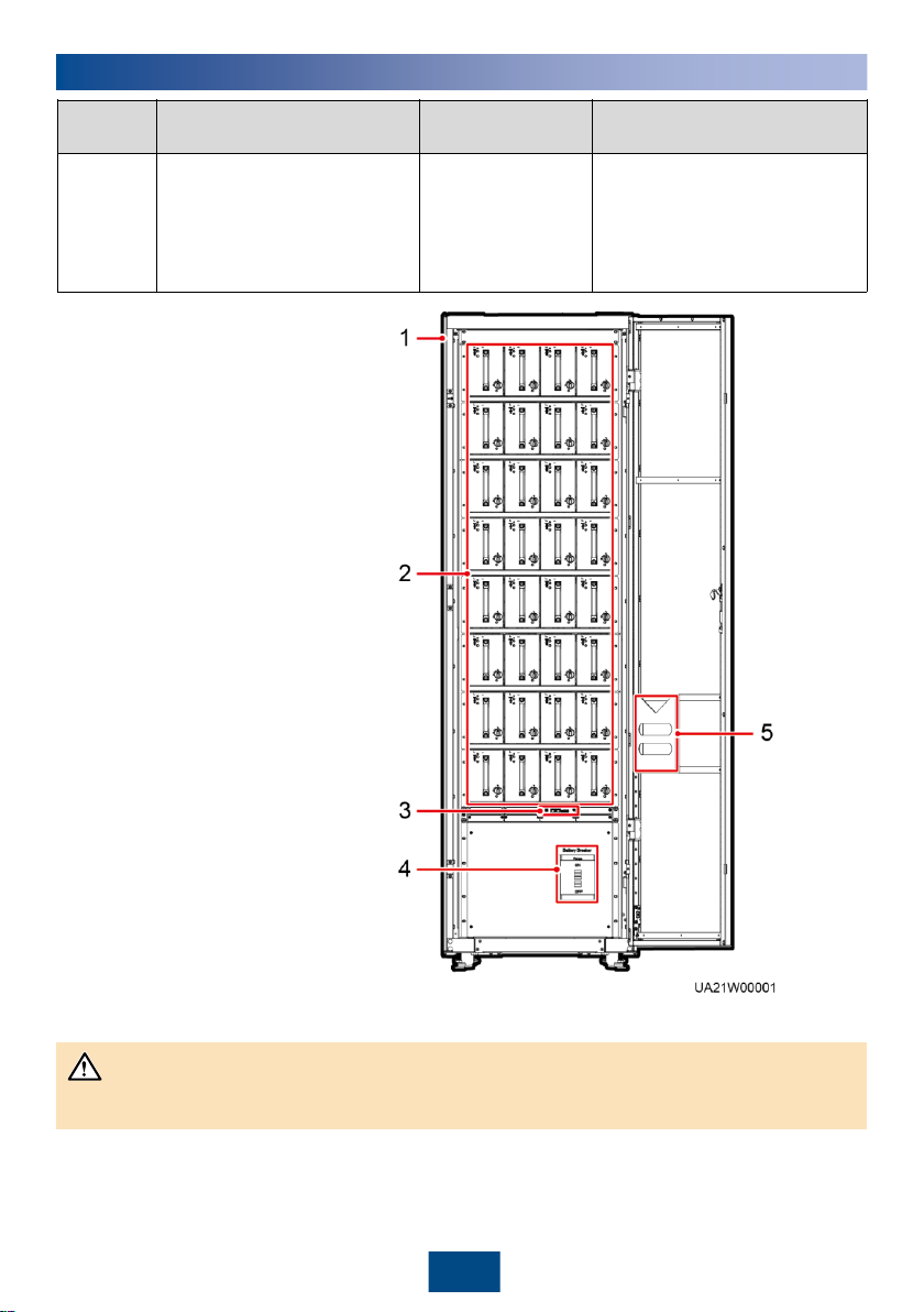
6. (Optional, for secured installation) Remove the rear cover from the cabinet and open the front
door of the cabinet.
To prevent electric shocks,
ensure that battery modules
are not installed before
removing the rear cover from
the cabinet.
9. (Optional, for secured installation) After the cabinet is secured, reinstall the rear cover for the
cabinet.
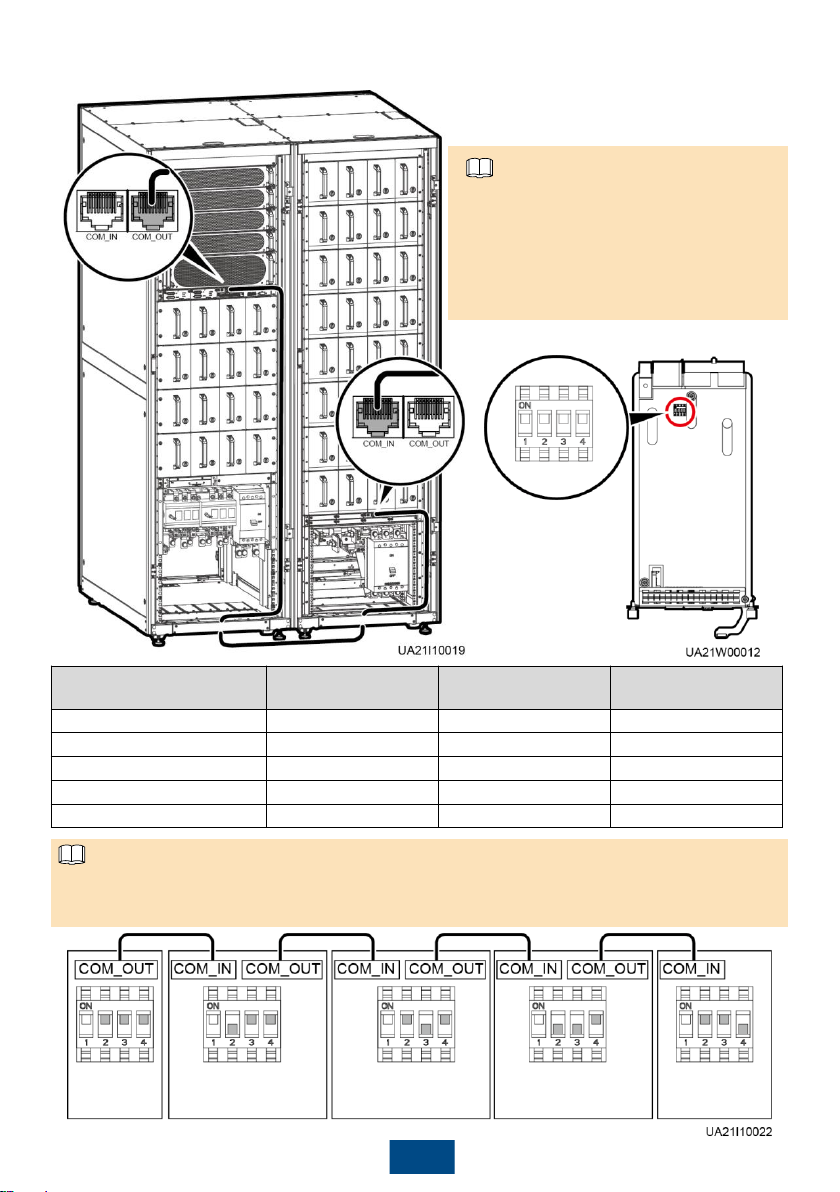
3Installing Cables
1. To prevent electric shocks, ensure that battery modules are not installed before connecting
cables.
2. When you choose to route cables by drilling holes, drill holes on the bottom plate, and paste
grommet strip to the hole edge to protect cables.
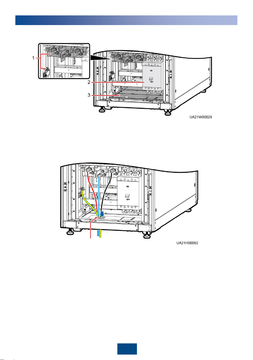
3. The battery +, N, and –cables can be routed only from the bottom. The signal cables can
be routed from the top or bottom. This document describes how to route cables from the
bottom as an example.


 user manual")


