Huayi MS2205 User manual

I
Contents
Safety Requirements ..............................................................................................1
Safety Instructions..................................................................................................1
Safety Sign...............................................................................................................2
General Description ................................................................................................2
Features ...................................................................................................................2
Appearance..............................................................................................................3
Knob Switch Operations.........................................................................................4
Button Switch Operations......................................................................................5
CD Display..............................................................................................................8
Instruction Manual..................................................................................................9
Test Data Storage.................................................................................................17
Read Saved Data ..................................................................................................17
RS232C Data Interface ........................................................................................18
Input Voltage and Current...................................................................................19
Backlight Display...................................................................................................19
Auto Power Off......................................................................................................19
Diagram of Safe Holding......................................................................................20
Power curve diagram ...........................................................................................20
Battery-low Indication..........................................................................................22
Battery Replacement............................................................................................22
General specification............................................................................................23
Technical specification .........................................................................................23
Accessories ............................................................................................................26

1
Safety Requirements
Please carefully read the instruction manual before using the tester, and pay special
attention to “Warning” content. Please follow instructions under “Warning”.
1. Please be very careful when test voltage is higher than AC 30 V, and do keep
in mind that your finger shall not exceed the hand-shielding part of the test
probe.
2. Do not measure voltage which is higher than the allowed input limit.
3. Before use, please check the meter and test probe; do not carry out testing in
case the test probe is naked, tester housing is damaged, or there is no LCD
display, etc..
4. It meets requirements of safety standards only when the meter is used together
with the supplied test probes. In case the test probe is damaged and needs
replacement, it is required to replace it with a test probe of the same model
and identical electrical specifications.
5. Please never carry out any voltage measurement whenever the test probe is
inserted in any current outlet.
6. Please do not expose the meter to strong light, high temperature, or dampness.
Before use, please carefully read this instruction manual.
Especially safety contents!
Safety Instructions
The three-phase clamp-type digital power meter is designed and manufactured in
accordance with international standard, IEC61010-1, and international safety
specification, IEC1010-2-032, and the meter strictly follows the safety standard of
double-insulation AC 600 V CAT III.
Warning

2
Safety Sign
Important safety signs; please refer to instruction manual
High voltage hazard
Earthing
Double insulation (Category-II safety equipment)
Battery low Indicator
General Description
The 3-phase clamp-type digital power meter is a hand-held intelligent harmonic
power tester, with both functions of digital current testing and power testing. The
tester is comprised of three channels including voltage, current, and power as well
as a micro single chip system, and it is equipped with a powerful software for
measurement and data processing functions; it can measure, calculate, and display
voltage, current, active power, power factor, apparent power, passive power,
frequency, harmonic parameters, with stable performance and operation
convenience. The meter is especially suitable for the measurement and examination
of on-site power equipment and power-supplying circuits; with hand-held clamp
structure, small volume, and light weight, it can be easily carried by the user, which
makes it easy and fast for doing measurement. For measurement of
sing-phase/three-phase power, The meter is your ideal choice.
Features
1. The meter can be used for testing power, voltage, current, peak value, phase,
frequency, power factor, phase angle, and reaction factor, etc. of
single-/three-phase circuit; automatic phase sequence testing is possible for
3-phase measurement.
2. True effective value measurement: accurate measurement is possible even

3
with serious distortion in current waveform.
3. Low-consumption high-speed single-chip microprocessor is employed and
sophisticated algorithm is applied, as a result, results can be obtained rapidly
and precisely, and up to 20 harmonics and distortion value thereof can be
measured.
4. It is equipped with a large-size memory for saving up to 100 groups of test
parameters.
5. It is equipped with RS232C communication and recording interface and
dedicated WINDOWS graphics software.
6. Hand-held, clamp-type structure, with light weight, convenient for carry-on.
Appearance
3 PHASE
1PHASE
1PHASE
HARM
HARM
1
2
3
4
5
6
7
8

4
1. Current clamp size: Φ50 mm
2. HOLD button :DATA HOLD button; press down HOLD button, and the last
reading will be held and displayed on the display, and “HOLD” symbol will
be shown; press HOLD button again, and the meter will switch back to
normal measurement mode.
3. Function-switching knob :Rotation knob for selecting different measuring
function
4. Function-selection button: Button for operating the measuring functions
5. Input terminal
Terminal
Function
FunctionFunction
Function
V1
V1V1
V1
Input terminal for measuring the first phase; use yellow test probe for
connection.
COM/V2
COM/V2COM/V2
COM/V2
Input terminal for measuring the 2nd phase; use black test probe for
connection. Common terminal: ground input terminal (earthing) for
all measuring functions; use black test probe for connection.
V3
V3V3
V3
Input terminal for measuring the 3rd phase; use green test probe for
connection.
6. LCD display :4-digit digital display; 7-section LCD for displaying
measurement operation function, test result, and unit sign.
7. Trigger :Press down the trigger, and the clamp will open; release it, and the
clamp will close.
8. RS232C interface: Dedicated optical-electrical interface wire is used for
online communication with PC, as well as for recording data and data trend
curve in PC.
Knob Switch Operations
The function-switching knob is used for powering-on and for switching to any
measurement function in the following table.

5
Knob position description
Sign
Knob position
Functions
OFF Powering-off position For powering-off
KW
(
((
(
1
phase
)
))
)
Active power position For measuring active power, etc.
Φ(1 phase)
Single-phase/phase-angle
Test position
For measuring phase angle, such as cos
Φand sin Φ, etc.
KW/Φ(3
phase)
3-phase apparent power
position
For measuring 3-phase apparent pow
er, etc.
A ~ AC-current harmonics te
st position
For measuring AC-current harmonics
, etc.
V ~ AC-voltage harmonics te
st position
For measuring AC-voltage harmonic
s, etc.
Note:
When the meter is automatically powered off, be sure to switch the knob to
“OFF” position; turn on the meter after 5 seconds.
Button Switch Operations
Button descriptions
SN
Function-selection button
1 MODE Test-mode switching button
2 SET SET button
3 ICurrent test button
4 WATT Power test switching button
5 UVoltage test button
6 READ Data-Reading button
7 RS232 RS232C button
8 CLEAR Clear memory button

6
SN
Function-selection button
9 Backlight button
10
▲
Reverse-search button
11
▼
Forward-search button
12 REC/SAVE Data recording & storage button
13 HOLD Hold button
The following functions can be realized through button operations:
WATT Button
Under test mode, you can measure active power, apparent power, power factor, and
phase angle and display the results on LCD by pressing WATT button.
MODE Button
Under KW-test mode, you can press MODE button to switch the display of active
power and passive power; under A/V~ test mode, you can switch the display
among total harmonic distortion rate F, r, and harmonic percentage.
SET Button
Under test mode, you can press SET
button and then press
▲
and
▼
button to
set the range of current and voltage, and then press this button again to return. This
button serves as CONFIRMATION button during storage and deleting.
U Button
Under test mode, you can press this button to test voltage of the present circuit, and
display the measured voltage of the present circuit on display.
READ Button
Under HOLD mode, you can press this button to display the stored data; press this
button again to return.
I Button
Under test mode, you can press I button to measure current of the present circuit
and display the measured current of the circuit by the clamp on LCD.
RS232 Button

7
Under test mode, you can press RS232 button to transfer the present test result to
PC through a dedicated interface wire supplied for the meter so as to record/print
data and data trend graph.
Before pressing RS232 button for data transferring, the supplied RS232C interface
wire shall be connected to RS232C interface socket of the meter and PC COM port,
before realizing communication functions.
CLEAR Button
Under data-reading mode, you can press CLEAR button and then press SET
button to clear the test data which is stored in the meter under a specified number.
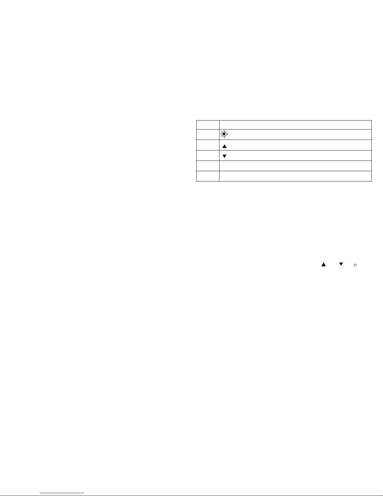
Button
You can press button to turn on or off the backlight. After it is turned on for 20
seconds, the backlight will automatically be turned off.
▲
Button
Under VOLTAGE-RANGE-SETUP mode, you can press
▲
button to change
the voltage test range. During testing harmonics, you can change the times
of harmonics.
When reading the saved data, you can press
▲
button to search backward t
hestored data and show it on LCD. With every press of the button, the sear
chingcursor will move one step backward to the previous data.
▼
Button
Under CURRENT-RANGE-SETUP mode, you can press
▲
button to change
current test range. During testing harmonics, you can change the times of
harmonics.
When reading the saved data, you can press
▼
button to search in the forward
direction the stored data and show it on LCD. With every press of the button, the
searching cursor will move one step forward to the next data.
REC/SAVE Button
Under TEST mode, you can press REC/SAVE button to display the max. /min.
power, current, voltage that is currently measured; under DATA HOLD mode,
press this button to display the stored number; press SET button again to save the

8
held data in the meter. Up to 100 groups of data can be stored in the meter.
HOLD Button
After measurement, press this button to hold this data on LCD; after powering-off,
data will display.
CD Display
LCD symbol
Description
LCD symbol
Description
RS232 Data transfer REC Data recording
APS Auto
powering-off
F Fast
HOLD Data holding S Slow
LAG Phase angle lag LEAD Phase angle lead
Battery power
indication
o Phase angle
(degree)
SIN
Φ
Reversed power
factor
COS
Φ
Power factor
RST 3-phase
Normal phase
AC symbol Reversed phase
Phase lacking
Negative symbol
MIN Minimum value MAX Maximum value
USED Used MEMO Save

9
LCD symbol
Description
LCD symbol
Description
READ Read V Voltage
W Watt
A
Current
VAr Passive power Hz Frequency
VA Apparent power
PEAK Peak value
% Harmonic
percentage High-voltage
warning sign
% THD Total harmonics distortion ratio
H01F Total harmonics distortion ratio F (relative to base wave)
H01r Total harmonics distortion ratio r (relative to real effective
value)
Instruction Manual
AC voltage (V) measurement
HARM
M A S TE C H
TL88-1
UL
M A S TEC H
TL88-1
UL
AC
V

10
Switch
Inputting
terminal V1
Inputting
terminal V2
Inputting
terminal V3
Test object
V ~
V1 socket
COM/ V2 socket
N/A
1-phase
V1 socket
COM/ V2 socket
N/A
2-phase
V1 socket
COM/ V2 socket
V3 socket
3-phase
1. According to the connection mode as above Table , switch the function
switching knob to V~, select corresponding sockets from V1, V2, or V3
terminal, and insert the test wire.
2. Connect the two test probes V1, V2 to the power source or load to be tested.
The meter will automatically test and display the result, and the present
harmonics percentage will be shown on the following line.
3. Under voltage test mode, press SET button to show ”Auto V” and “Auto A”
on LCD, and press
▲
to select a proper voltage range, and then press SET to
return.
4. Press MODE button to show harmonics percentage on LCD, and the total
harmonic distortion ratio F and R will be cyclically displayed. Press
▲/▼
button to display value of each measurement of the harmonic.
5. When input voltage is greater than 50 V, “ ” sign will be shown on LCD,
prompting you to pay attention to safety.

11
AC-current (A) measurement
1. Switch the function knob to A~ position;
2. Pull the trigger to open the clamp, and then clip a wire which is to be tested;
the measured current value will be automatically shown on LCD
3. Press MODE button to show harmonics percentage on LCD, and the total
harmonic distortion ratio F and r will be cyclically displayed.
4. Press
▲/▼
button to display value of each measurement of the harmonic.
5. If current of the wire being tested is greater than 1000 A (RMS), ”OL” symbol
will be displayed instead of current value.
Note:
1. You can select 50/60-Hz FIXED/AUTO frequency test (AUTO). When input
waveform fluctuates, displayed harmonic values can be kept stable if
50/60-Hz FIXED mode is selected.
NEUTRAL
3
2
1

12
2. Under AUTO frequency test mode, FFT calculation is performed only when
base-wave frequency is between 45 and 65 Hz; harmonic analysis is not
performed when base-wave frequency exceeds this range.
Test of single-phase circuit
1. Clip the clamp on the test wire of the power supply or load. If the user needs
to measure a certain phase of the 3-phase circuit, then the clamp should clip
on the wire of the same phase.
2. switch the function switching knob to KW position, select corresponding
input sockets from V1 or V2 terminal and insert the test wire.
3. After it is correctly connected, you can measure single-phase power (active
power, power factor, apparent power, passive power, voltage, current, phase
angle, peak value of voltage and current, and frequency):
4. The meter will carry out automatic measurement and display active power,
and voltage/current value of the load being tested will be displayed on the
bottom line of LCD; press down MODE button, Var value of passive power
will be displayed on LCD; press WATT button to display apparent power and
3 PHASE
1PHASE
1PHASE
HARM
HARM
Power supply side
Load
Yellow
Black

13
power factor (cos Φ); negative power factor signifies that the load being tested
is a load with capacitor characteristics.
5.
The maximum measurement range of active power kW is 600 kW; if this
range is exceeded, “OL” symbol will be displayed beyond this range. If
voltage being tested is greater than 600 V, or current being tested greater than
1000 A, “OL” symbol will be displayed on LCD.
6. The min. input voltage is 50 V and the min. input current is 2A; if active
power value is smaller than this limit, “0.00 kW” will be displayed in stead of
active power value.
7. Press SET button to display AUTO, and press
▲/▼
button to set
measurement range for voltage and current; press SET button to return.
8. Press down I button, current value, current peak value and frequency will be
displayed on bottom line of LCD.
9. Press down U button, voltage value, voltage peak value and frequency will be
displayed on bottom line of LCD.
10. Press REC/SAVE button to show MAX and MIN
11. Passive power is a value not directly measured; equation for kVAr is
kVAr
2
=kVA
2
-kW
2
; its value is calculated by software based on the measured
voltage, current and active power, and displayed on LCD.
cosΦ, sinΦ, and phase angle measurement
1. Switch the function-switch knob to Φ(1 phase) position, and the test wire is
inserted to V1/V2 input terminals.
2. The meter will automatically measure and display power factor, voltage value
and current value.
3. Press WATT button to display phase angle, power factor (cos Φ), and sinΦ;
negative power factor signifies that the load being tested is a load with
capacitor characteristics.
4. Press down Ibutton, current value, current peak value and frequency will be
displayed on bottom line of LCD.

14
5. Press down Ubutton, voltage value, voltage peak value and frequency will be
displayed on bottom line of LCD.
6. Press REC/SAVE button to show MAX and MIN
7. Press SET button to display AUTO, and press
▲/▼
button to set
measurement range for voltage and current; press SET button to return.
8. After measuring, press HOLD button to keep showing the data on LCD, and
press REC/SAVE button to display the saved serial number, and then press
SET button to confirm it and return.
Single-phase three-line circuit
the process for measuring power and power factor for single-phase three-lin
e circuit is the same as that for single-phase two-line circuit, where the blac
k clip is connected to the middle wire, and the red clip and clamp-type sen
sor are simultaneously connected to all test wires.
Measuring power of 3-phase load (for balanced load)
1. In the case of balanced load, process for measuring power and power factor of
3-phase 4-line circuit is the same as that for 3-phase 3-line circuit, and it is not
needed to use the middle line.
2. 3-phase total power parameters are referred to as total active power, total
passive power, total apparent power, and total power factor of 3-phase circuit.
The meter cannot carry out 3-phase energy measurement. In the case of
P
o
w
e
r
s
u
p
p
l
y
s
i
d
e
Red
Black
Load
3 PHASE
1PHASE
1PHASE
HARM
HARM
Black
Red
1PHASE

15
balanced load, measured result is accurate, while error of total power will
increase if power variation is large.
3. switch function-switching knob to kW/Φ(3 phase) position, and connect test
clamp to phase-1 test wire of the load, and then connect V1 terminal / yellow
test probe, V2 terminal / black test probe, and V3 terminal / green test probe
to the live line of phase 1, phase 2, and phase 3, respectively, of the 3-phase
load without connecting the netural line.
4. After the test lines are properly connected, the meter will automatically
perform measurement and display power, voltage, current, and whether a
phase is missing.
5. Press MODE button to display Var value of passive power on LCD.
6. Press WATT button to display apparent power, power factor (cos Φ), phase
angle, and sinΦ; negative power factor signifies that the load being tested is of
capacitor characteristics.
7. Press down I button, and current value, current peak value and frequency will
be displayed on LCD.
8. Press down Ubutton, and voltage value, voltage peak value and frequency
will be displayed on LCD.
9. Press SET button to display AUTO, and press
▲/▼
button to set the
measuring range for voltage and current, and then press SET button to return.
10. After measuring, press HOLD button to keep showing the data on LCD, and
press RES/SAVE button to display the saved serial number, and then press
SET button to confirm it and return.
Phase sequence test
1. the meter will automatically test the phase sequence.
2. The display of signifies normal phase sequence.
3. The display of signifies reversed phase sequence.
4. The display of signifies missing phase.
5. During measurement, press REC/SAVE button to show MAX and MIN and
record the results. Then, press REC/SAVE button to transfer the test result to
PC through infrared communication wire.

16
1PHASE
Power supply side
Load
Red
Yellow
Black
Measurement of power and power
factor of 3-phase 3-line circuit
P
o
w
e
r
s
u
p
p
l
y
s
i
d
e
Red
Black
Load
Black
Red
1PHASE
1PHASE
Another mode for measuring power of
3-phase 3-line circuit

17
Measuring power of 3-phase 4-line load (for imbalanced load)
In the case of imbalanced load, the measuring process is the same as that of
1-phase 2-line system, and the measuring mode is set as 1-phase mode. connect the
black clip to the middle line, and then simultaneously switch the yellow clip and
clamp sensor to corresponding wires; under this mode, power and power factor of
each line can be tested. (To test phase sequence, connect voltage clips to the three
lines one by one, with the middle line not connected)
Test Data Storage
When the meter is under HOLD mode, you can press REC/SAVE button to display
the serial number to be saved and press
▲/▼
button to select serial number, and
then press SET button to confirm saving. Test results are saved in the meter, and up
to 100 groups of data can be saved in the meter.
Before pressing SET button, if you press REC/SAVE button to quit saving, data
will not be saved, and it will return to the previous menu.
Read Saved Data
1. When any data is saved in the meter, you can switch it to READ SAVED
DATA position for data retrieving.
2. Switch function-switching knob to SEARCH position and press HOLD
button to display HOLD.
P
o
w
e
r
s
u
p
p
l
y
s
i
d
e
L
o
a
d
Red
Yellow
Black
Black
Red
Yellow
Yellow
Black
Red
1PHASE
1PHASE
1PHASE
Measurement of power and power factor of 3-phase 4-line circuit

18
3. Press READ button to show the saved serial number and data on LCD.
4. If you need to check the records stored previously or afterwards or harmonic
level, press
▲/▼
button to make selections.
5. when harmonic level data is displayed , press watt button, thenpress
▲/▼
button to select record number.
6. To delete data, just press CLEAR button, and CLR will be displayed; then,
press SET button to confirm it, and data will be deleted. Before pressing SET
button, if you press CLEAR button, data will not be deleted, and it will return
to the previous menu.
RS232C Data Interface
1. Insert RS232C interface wire into the socket on the meter, and rotate interface
wire clock-wise to lock the wire in the power meter; connect the standard
RS232C plug on the other end of the interface wire to PC COM port, and now
real-time data transferring with PC can be realized through the infrared
communication RS232C interface. If you wish to unplug the RS232C
interface wire from the power meter, firstly, rotate the interface-wire plug in
the meter counter-clockwise, then, take it out after the interface wire is
unlocked.
2. If you press RS232 button, the currently measured data can be recorded in
real time under WINDOWS;
3. If you press HOLD button, and then READ button, and then RS232 button,
the saved data can be uploaded to PC.
4. This software can be used for managing real-time data records, plotting, and
printing output, etc..

19
(RS232C connection diagram)
Input Voltage and Current
During power measurement, if input voltage is over 600 V (RMS) or current over
1000 A (RMS), “OL” symbol will be displayed and bar symbol shown in full scale.
When input voltage is over 50 V, “ ” sign will be shown on LCD, prompting
you to pay attention to safety.
Backlight Display
Press , the backlight will be lit up, and it will then be automatically turned
off after about 20 seconds.
Auto Power Off
1. If there is no function change or button press fo 10 minutes ,the meter will
automatically turn power off , When the meter is automatically powered off,
be sure to switch the knob to “OFF” position; turn on the meter after 5
seconds.
2. Holding the button SET&CLEAR down while turning the meter on,Disables
automatic power -off
3. automatically powered off function will be disabled while the meter in
MAX/MIN Record mode and the meter performing communicate with PC
software
RS232-C
INTERFACE
OPTICAL
6 0 0 V
M A X
~
3
R S2 3 2O P T IC A L IN T ER F AC E
计 算 机
PC COM
Table of contents
Other Huayi Measuring Instrument manuals