HUAYUAN SLG-200HF User manual

SLG-200/300/400HF
PLASMA CUTTING MACHINE
MANUAL
INSTRUCTION
(PLEASE READ IT CAREFULLY BEFORE OPERATION)

Safety Depends on You
HUAYUAN arc welding and cutting equipment are designed and built with ample safety consideration. However, proper
installing and operating can ensure your safety.
DO NOT INSTALL, OPERATE OR REPAIR THIS EQUIPMENT CASUALLY WITHOUT READING THIS MANUAL THROUGHOUT.
Special Notes (Very Important):
1. Pay attention to avoiding the machine falling down when it is placed on the gradient ground.
2. It is forbidden to unfreeze the pipeline by the cutter.
3. The shield rank of this series of cutter is IP21S, so working in rain is not suitable.
4.The cutter has external static characteristic with rated duty cycle 100%, which means the machine can work continuously
at the rated cutting current. The machine has the function of thermal protection. When the internal temperature exceeds a
set temperature, thermal protection moves on and the abnormal indicator lamp on the panel turns ON, then there is no
output in cutter. The machine can become normal and work only after the internal temperature drops down and the
abnormal indicator lamp on the panel turns OFF.
5. The electric magnetic compatibility of this plasma cutting power source is A.
Purchase Date:___________________
Serial Number:___________________
Machine Model: ___________________
Purchase Place: ___________________

C a u ti o n s
Arc and arc rays can hurt.
All performing welding workers ought to have health qualification from the authority organization to prevent you and
others from arc radiation and burn. It should be prevented for children to enter into dangerous area as well.
Carefully read the following important items and the welder safety bye-law from the authority organization. Be sure that
qualified professionals perform all installation, maintenance and repair procedures.
1 Electric shock: The welding circuits are not insulated when welding. If you touch the two output
electrodes of the machine with your bare skin at the same time, it will lead to electric shock,
sometimes even fatal dangers. Users need to follow the items below to avoid electric shocks:
If possible, lay some insulating materials, which are dry and large enough, in your working field.
Otherwise, use the automatic or semiautomatic welding machine, DC welding machine as possible as you can.
Components in the automatic and semiautomatic welding machine such as the welding wire reel, feed wheel,
contact tip and welding head are all electric components. .
Always be sure the machine has been connected perfectly to the work piece with the work cables and should be as
close as possible to the working area.
The work piece should be grounded perfectly.
Make sure that the insulating material of the electrode holder, the grounding clamp, the welding cable and the
welding head are not affected by damp, mildewed or spoil, and be replaced momentarily.
Never dip the electrode in water for cooling.
Never touch electric components of two welding machines at the same time, because this voltage is supposed to
be two times of welding voltage while the grounding mode is not clear.
While working high above the ground or other places having the risk of falling, please be sure to wear safety belt to
avoid losing balance caused by electric shock.
2 Arc: Use an arc welding mask to protect your eyes and skin from sparks and the rays of the arc, pay
special attention to the filter glass, which must be conformable to the national standard.
Use clothing made from durable flame-resistant material or sailcloth to protect your skin from
hurting by the arc rays.
Remind other nearby personnel before working lest arc rays hurt them by accident.
3 Fumes and Gases: Welding may produce fumes and gases hazardous to health. Avoid breathing these
fumes and gases. While working in limited room, use enough ventilation and/or exhaust to keep fumes
and gases away from the breathing zone, or use the respirator. Do not weld at the same time when
using of degrease, cleaning or spraying operations. The heat and rays of the arc can react with these
gases to form phosgene, a highly toxic gas,
Some protective gases used in welding might displace the oxygen in the air, and can lead to hurt or even death.
Read and understand the manufacturer’s instructions for this equipment, and validate the health certification of
consumptive materials, make sure they are innocuous.
4 Spatter: Spatter can cause fire or explosion.
Remove fire hazards from the welding area. Remember that spatter from welding can easily go
through small cracks and touch fire hazards. Protect all kinds of lines going though welding area,
including hydraulic lines in the wild.
Where compressed gases are to be used in the field, special precautions should be used to prevent explosion.
When welding stops, make certain that no live part is touching the work piece or the work stage. Accidental
contact can create a fire hazard.
Do not weld containers or lines, which are not proved to be innocuous.
It is very dangerous to heat, cut or weld tanks or containers at entry holes. Does not start work until the proper
steps have been taken to insure that there is no flammable or toxic gas.
Spatter might cause burn. Wear leather gloves, heavy shirt, cuff-less trousers, high shoes and a cap over your hair
to prevent from burning by spatter. Wear the ear shield when performing sideways or face up welding. Always

wear safety glasses with side shields when being in a welding area.
The welding cables should be as close to the welding area as possible, and the short, the better. Avoid welding
cables going through the building framework, lifting chains, AC or DC cables of other welding machines and
appliances. The welding current is strong enough to damage them while having short circuit with them.
5 Cylinder: Damage of it might cause explosion.
Make sure that the gas in the storage cylinder is qualified for welding, and the decompression
flow-meter, the adapter and the pipe are all in good condition.
Make sure that the installation of cylinder is by the wall and bundled tightly by a chain.
Be sure to put the cylinder in the working space with no crash or shake, and far from welding area.
It is forbidden to touch cylinder with the welding clamp or the work cables.
Avoid facing the cylinder while installing the decompression flow-meter or the gasometer.
When not working, please tighten the valve.
6 Power: (For electrically powered welding and cutting equipment) Turn off input power before
installation, maintenance and repair, so that avoid accident.
HUAYUAN welding equipment is Ι class safeguard equipment; please install the equipment in
accordance with the manufacturer’s recommendations by specific persons.
Ground the equipment perfectly in accordance with the manufacturer’s recommendations.
7 Power:(For engine driven welding and cutting equipment)
Work in ventilated place or outdoors.
Do not add fuel near to fire or during engine starting or welding. When not working, add fuel after
engine is cooling down; otherwise, the evaporation of hot fuel would result in dangers. Do not
splash fuel out of the fuel tank, and do not start the engine until complete evaporation of the
outside fuel.
Make sure that all the safeguard equipment, machine cover and devices are all in a good condition.
Be sure that arms, clothes and all the tools do not touch all the moving and rotating components
including V belt, gear and fan etc.
Sometimes having to dismantle some parts of the device during maintenance, but must keep safety awareness
strongly every time.
Do not put your hand close to fans and do not move the brake handle while operating.
Please remove the connection between the engine and the welding equipment to avoid sudden starting during
maintenance.
When engine is hot, it is forbidden to open the airtight cover of the radiator water tank to avoid hurt by the hot
vapor.
8 Electromagnetic: Welding current going though any area can generate electromagnetic, as well as the
welding equipment itself.
Electromagnetic would affect cardiac pacemaker, the cardiac pacemaker users should consult one’s
doctor first.
The effect of electromagnetic to one’s health is not confirmed, so it might have some negative effect to one’s
health.
Welders may use following method to reduce the hazardous of electromagnetic:
a. Bundle the cable connected to the work piece and the welding cable together.
b. Do not en-wind partially or entirely your body with the cable.
c. Do not place yourself between the welding cable and the ground (work piece) cable, if the welding cable is by your
left side, then the ground cable should be by your left side too.
d. The Welding cable and the ground cable are as short as possible.
e. Do not work near to the welding power source.

9 Lift Equipment: carton or wooden boxes package the welding machines supplied by HUAYUAN. There
is no lifting equipment in its wrapper. Users can move it to the prospective area by a fork-lift truck, and
then open the box.
If having rings, the machine can be transited using rings. While HUAYUAN Welding Machine
Manufacture reminds users, there is possible risk to damage the welding machine. It is better to
push the welding machine moving in use of its rollers unless special situations.
Be sure that the appurtenances are all removed off when lifting.
When lifting, make sure that there is no person below the welding machine, and remind people
passing by at any moment.
Do not move the hoist too fast.
10 Noise: HUAYUAN Welding Machine Manufacture reminds users: Noise beyond the limit (over 80
db) can cause injury to vision, heart and audition depending on oneself. Please consult local medical
institution. Use the equipment with doctor’s permission would help to keeping healthy.

CATALOGUE
Summary............................................................................................................................................................ 1
1. Components........................................................................................................................................... 1
2. Connection............................................................................................................................................. 1
3. Features..................................................................................................................................................2
4. Usage......................................................................................................................................................2
5. Symbol Instruction................................................................................................................................. 2
6. Working Environment............................................................................................................................ 3
Technical Parameter...........................................................................................................................................3
1. Power source SLG-200HF、SLG-300HF、SLG-400HF........................................................................... 3
2. Arc initiator QFK-E1................................................................................................................................6
3. Requirements of gas supply...................................................................................................................7
4. Requirement of torch coolant................................................................................................................7
Panel Function....................................................................................................................................................8
1. Power source front panel.......................................................................................................................8
2.Arc initiator panel..................................................................................................................................11
3. Secondary menu.................................................................................................................................. 12
Installation........................................................................................................................................................13
1. Acceptance inspection......................................................................................................................... 13
2. Product defect......................................................................................................................................13
3. Installation requirement...................................................................................................................... 13
4. Noise.....................................................................................................................................................13
5. Ground connection and shield installation..........................................................................................13
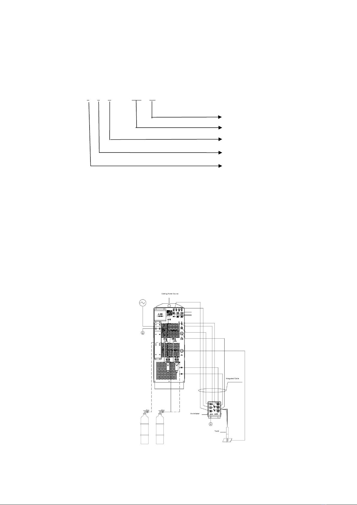
6. Installation drawing..............................................................................................................................14
7. Installation of plasma cutting power source(Part A)..................................................................... 16
8. Installation of arc initiator(5-2 Part B)........................................................................................... 17
9. Torch installation(5-2 Part C)..........................................................................................................18
10. Cable and hose installation(5-2 ○
1~○
18)...................................................................................... 18
11. Filling coolant liquid........................................................................................................................... 22
12. Setting of gas supply.......................................................................................................................... 22
13. Optimize the cutting quality.............................................................................................................. 23
14. Inspection before operate................................................................................................................. 25

15. Cutting parameter table.....................................................................................................................25
Maintenance.................................................................................................................................................... 31
1. Operation process................................................................................................................................31
2.Gas clean............................................................................................................................................... 31
3. Error code and trouble shooting..........................................................................................................32
4. Control panel indicator instruction......................................................................................................35
5. Initial inspection...................................................................................................................................36
6. Air filter cartridge replace....................................................................................................................36
7. Cutting machine cooling system maintenance....................................................................................37
8. Maintenance........................................................................................................................................ 38
Appendix.......................................................................................................................................................... 39
1. Cutting machine spare parts................................................................................................................39
2. Arc initiator spare parts....................................................................................................................... 39
3. Circuit diagram..................................................................................................................................... 40
4. RS485 communication protocol...........................................................................................................44

1
Summary
1. Components
1)
Power source
S L G - □□□ HF
Inverter air plasma cutting power source SLG-200HF、SLG-300HF、SLG-400HF,is a constant current power source. All
outside cable connect terminal same. This power source can communicate with CNC controller through RS-485. The plasma
cutting system can only control by the ON/OFF switch on the machine.
2) Arc initiator
Plasma arc initiator QFK-E1 is used for the HF pulse start, then cause guide arc,when the guide arc reach the workpiece,
it will cause main arc.Another function for the arc initiator is to receive the control signal from power source, to replace
plasma preflow gas and cutting flow gas.The arc initiator must work together with the plasma power source
3)Torch : Torch HYC-400B transfer the current to workpiece through arc to get metal cutting.
2. Connection
Rated cutting current
Cutting
Plasma cutting
Series code
Product code

2
3. Features
1) Rated duty cycle 100%(40℃),suitable for heavy industry。
2) With analogue and digital signal connector, special used for automatic cutting equipment, like CNC and robot.
3) Separate arc initiator and power source, with short torch cable and small interruption for automatic equipment,
short gas circuit,fast reaction, stable gas flow, high arc strike success and good cutting quality
4) Separate adjust plasma gas and shield gas pressure, suitable for many gas cutting procedure, especially suitable for
O2plasma gas/Air shield gas. Compare with normal plasma cutting, this machine can get better carbon steel
cutting quality and efficiency
5) Professional torch cooling system, with import big flow pump and big power heat sink construction, so that torch
work stable and constant
6) Gas pre send/gas delay shut/current up slope time can be set
7) Machine have overheat/gas pressure lack/coolant capacity and flow lack/voltage lack/over voltage and lack phase
protection
8) With torch monitoring function, with alarm warning, can remind consumables replace to improve the torch life
4. Usage
It’s used for cutting carbon steel, alloy steel, nonferrous metals and so on.
It is suitable for pressure vessel, chemical vessel, industry electric power installation, chemical construction, aeroplane
industry, vehicle manufacturing, etc.
5. Symbol Instruction
POWER ON
POWER OFF
PRESS OUT, POWER ONE
PRESS IN, POWER OFF
DANGER
VOLTAGE INPUT
FUSE
CURRENT OUTPUT
OVER HEAT
GAS INPU
PLASMA GAS
SHIELD GAS
COOLANT LEVEL
COOLANT FLOW
COOLANT INPUT
COOLANT OUTPUT

3
WORK CABLE
GROUND CONNECT
NEGATIVE
WARNING!
READ INSTRUCTION MANUAL
CONNECT WITH TORCH ELECTRODE
(CONNECT WITH MACHINE
NEGATIVE POLE)
PILOT ARC(CONNECT WITH
NOZZLE)
TORCH
CUTTING
6. Working Environment
Note:Under following situation, the cutting machine may can;t meet the technology require or
can’t working normal
Under any circumstance, the ambient temperature should higher than the coolant freezing
point, as the freezing coolant will cause cooling system damage, make the copper tube\pump and torch
crack.
The coolant in the water tank must be clean up if the machine not use or stock for a long time
1. Please use the machine in a clear place without any of dust, corrosive gas and flammables and explosives; Do
not use it in open air and rain;
2. Required air relative humidity should ≤90%(at 20℃),40℃≤50%(at 40℃);
3. Environment temperature range should be at-10℃~40℃;
4. The coolant liquid can not be frozen when use;
5. Any metal materials can not be put on or insider the power source;
6. Keep the machine away from the wall of some other closure things at least 50cm, two machines distance at least
50cm.
7. Use it under altitude lower than 1000m.
Technical Parameter
1. Power source SLG-200HF、SLG-300HF、SLG-400HF
1) Basic parameter
ITEM
UNIT
PARAMETER
SLG-200HF
SLG-300HF
SLG-400HF
Rated power supply
V/Hz
3-380/415±15% 50/60
Rated input capacity
kVA
53
72
93
Rated input current
A
80
110
140
Rated output
current/voltage
A/V
200/200
300/200
400/200

4
Rated open circuit voltage
V
360
370
370
Rated duty cycle
-
100%(40℃)
Efficiency
-
93%
93%
94%
Power factor
-
0.79
0.89
0.91
Rated current adjust range
A
40~200
60~300
60~400
Arc voltage output ratio
-
1:1
Arc strike mode
-
Non-contact
Plasma gas
-
Air/O2/N2
Shield gas
-
Air/N2
Gas pressure
MPa
0.5~0.7
Quality cutting thickness
(C.S.)
mm
25
32
40
Insulation grade
-
F
Cooling mode
-
Air cooling
Protection grade
-
IP21S
Note: The cutting thickness data got from our standard parts testing, even it can cut thicker material, but it is suggest
that 80% of the workpiece within the above thickness range. It better to cut from the edge, if really need piercing,
then the piercing thickness must no more than the above thickness
2)Dimension
3-1 SLG-200HF dimension and weight

5
3-2 SLG-300HF dimension and weight
3-3 SLG-400HF dimension and weight

6
3) Characteristics
3-4 SLG-200HF
3-5 SLG-300HF
3-6 SLG-400HF
2. Arc initiator QFK-E1
3-7 QFK-E1 dimension and weight

7
3. Requirements of gas supply
Requirement of gas quality, pressure and flow
Gas
Quality
Pressure
Flow
O2
Purity ≥99.5% (Suggest using liquefied gas)
Clean, dry and oil-free
0.5MPa~0.7MPa
≥70 L/Min
N2
Purity ≥99.9% (Suggest using liquefied gas)
Clean, dry and oil-free
0.5MPa~0.7MPa
≥195L/Min
AIR
Clean, dry and oil-free
0.5MPa~0.7MPa
≥190L/Min
Note:
The Air in above table should accordance with the cutting parameter table, as following:
⑴Solid particle: grade 1, 0.1~0.5μm particle can’t be more than 100pc, 0.5~5.0μm particle can’t be more than 1pc per
1CBM air
⑵Temperature: grade 4, humidity pressure must be less or equal to 3℃
⑶Oil: grade 2, the density of the oil in air can’t be more than 0.1mg/m3
4. Requirement of torch coolant
Before transportation, all coolant in the machine has been take out, customer need full fill proper coolant before
operation
Warnings:
Warning! The cooling liquid is irritant to skin and eyes, if wrongly eat or drink, it hurts even kills.
If skin and eyes contact with the coolant liquid, please wash immediately with lot of clean water, then go to the hospital
to ask for help.
Notice! Do not use the anti-freezing solution as the coolant, it hurt the torch! To protect the
bump and torch cooling system, please do use the special coolant liquid.
The working temperature of the coolant liquid of this system is -12℃~40℃
The coolant box is empty when delivery out. Before fulling the coolant box, please check which coolant is suitable for
your environment. The standard coolant liquid of this cutting system is composed by 69.8% water, 30% propylene glycol
and 0.2% benzotriazole.
If working temperature is not in the range of -12℃~40℃, please check the suggestion of self-control mixed
coolant liquid below. To make the self-control mixed coolant liquid, please do use pure water in case of hurting the
cooling system.
The self-control mixed coolant liquid that used in low temperature (Under -12℃)
Notice! When the working temperature is lower than -12℃, the percentage composition of propylene glycol must
be improved. Or the frozen coolant may break the torch and pipes. Please reference to the below table for suitable
percentage composition of propylene glycol. However, the percentage composition of propylene glycol can not higher
than 50%.

8
The self-control mixed coolant liquid that used in high temperature (over 38℃)
The treated water can only be used as coolant when the environment temperature is higher than 0℃. The treated
water cool the system very well when used in a warm environment.
The treated water is a mixed water with water(which meet the below purity standard) and benzotriazole with
percentage of 300:1.
Water purity
It’s vital to control the CaCO3 content with a low level, to reduce the hurt to the cutting torch.
If use self-control mixed coolant liquid, please make sure the water always accord with the below table standard.
Both the lowest and highest index.
If use water without according with below lowest purity index, there will be too much precipitate on electrode,
which affect the water flow and make the arc not stable.
If use water without according with below highest purity index, there will be problem too. Too high purity
deionized water will leak from cooling system pipe.
Table 3 Related value of water purity
Related value of water purity
Conductivity μS/cm
(25℃)
Electrical resistor
mΩ•cm (25℃)
NaCl content
(ppm)
CaCO3content
(ppm)
Pure water (Just for
reference)
0.055
18.3
0
0
Highest purity
0.5
2
0.206
0.171
Lowest purity
18
0.054
8.5
7.35
Highest purity of drinking
water (Just for reference)
1000
0.001
495
428
Panel Function
1. Power source front panel

9
4-1 SLG-200HF
1) Coolant filter:filter coolant
2) Display knob:to exchange current/coolant flow/coolant temperature display. Press this know 5S without loss can start
the manual pump function.
“Manual pump”function:force to start the cooling system, the display knob automatically change to coolant flow
display.
3) Coolant temperature indicator:unit“℃”。
4) Liquid flow indicator: it lights on when the coolant liquid flow is higher than 1.9L/min;
4-2 SLG-300HF、SLG-400HF

10
5) Current display indicator:unit “A”。
6) Digital meter:display current, coolant flow, coolant temperature, error code and secondary menu
7) Gas pressure indicator:
Indicator always on:gas pressure normal
Indicator on 0.3s then off 0.3s:gas pressure shortage(<0.2MPa),machine can;t work
Indicator on 0.1s then off 0.1s:the machine have problem for pressure shortage before, but already recover to
normal, machine can work
8) Coolant level indicator:indicator always on, the coolant level normal; Indicator on 0.3s then off 0.3s, the coolant level
not enough, machine can;t work
9) Coolant flow indicator:indicator always on, the coolant flow normal; Indicator on 0.3s then off 0.3s, the coolant flow
not enough, machine can;t work
10) Starting indicator: it lights on when the cutting is start;
11) Over-heating indicator:
Indicator off: machine normal
Indicator on 0.3s then off 0.3s, the coolant temperature too high, or the inside parts IGBT over heat, machine
can;t work
Indicator on 0.1s then off 0.1s:the machine have problem for pressure shortage before, but already recover to
normal, machine can work
12) Power abnormal indicator:indicator always off, machine normal; Indicator on 0.3s then off 0.3s, machine lack phase
or over voltage or lack voltage, machine can;t work
13) Current adjusting knot: it adjust the cutting current; under the secondary menu, to adjust the secondary menu
parameter
14) Gas check indicator:turn on the gas check, the indicator on
15) Gas check knob:on/off the gas check function
16) Power switch:SLG-200HF is breaker control on/off, SLG-300HF、SLG-400HF is urgent stop knob, press this knob, power
off, turn the knob clockwise, power on
17) Coolant liquid inlet: Fulfill the coolant liquid;
18) Coolant liquid outlet: discharge the coolant liquid;
19) Plasma gas pressure adjust filter:Adjust the plasma gas(Air or N2) working pressure and filter the water
20) Shield gas pressure adjust filter:Adjust the shield gas(Air or N2) working pressure and filter the water
21) Plasma gas input connector:input plasma gas, it can be Air/ N2or O2according to the cutting requirements. When
input Air/ N2, it should through 19 filter, when input O2, customer need prepare good quality O2gas regulator to
adjust the gas pressure
22) Shield gas input connector:input shield gas, it can be Air or N2according to the cutting requirements
23) Ground connect screw:connect ground cable
24) Three phase input power cable connector:connect three phase input power
25) Control fuse:Control the circuit fuse
26) Solenoid valve power supply fuse
27) HF control fuse

11
28) Arc voltage output fuse holder: Arc voltage output fuse holder of cutting power source;
29) HF power supply connector: connect plasma arc initiator, control the HF power supply
30) Arc voltage output plug: the arc voltage of cutting power source output it 1:1,
31) Solenoid valve control connector: connect plasma arc initiator to control the solenoid valve work
32) CNC connector: connect with the CNC control signal
33) Robot connector: connect with the robot control signal
34) RS485 communication connector:connect with the automatic control equipment which have digital communication
signal
35) Protecting gas output plug: to connect the output gas pipe of protecting gas;
36) Pilot arc cable plug: to connect the striking arc cables;
37) Plasma gas output plug: to connect the output gas pipe of plasma gas;
38) Negative pole cable plug: to connect the negative pole cable;
39) Work-piece cable plug: it connects the work-piece cable (Work-piece cable is also called the ground cable);
40) Water coolant liquid inlet connector: to connect the coolant liquid return pipe;
41) Water coolant liquid outlet connector: to connect the coolant liquid supply pipe
2.Arc initiator panel
1) The plasma torch connector: the torch cable pass through this plug and connect with the corresponding
connectors in the initiator;
2) The grounding screw: to connect the grounding cable.
3) Solenoid valve control connector: connect with the solenoid valve control connector
4) HF power plug: connect with the power source “HF power”
5) Pilot arc cable plug: to connect the striking arc cable;
6) The plasma gas plug: to connect the plasma gas output pipe of the plasma power source;
7) Coolant liquid supply plug: to connect with the coolant liquid supply pipe of the plasma power source;
8) Coolant liquid return plug: to connect with the coolant liquid return pipe of the plasma power source;
9) The negative pole cable plug: to connect the negative pole cable;
10) The protecting gas plug: to connect the protecting gas output pipe of the plasma power source;

12
3. Secondary menu
Press gas check knob for 5s, come into secondary menu model, digital meter show the secondary menu code
Turn the encoder, adjust the secondary menu code(P01~P12), press display knob for confirmation, digital meter
show parameter
Turn encoder, adjust parameter value, press display knob for confirmation, storage the parameter, digital meter show
back to up step menu code
Press gas check knob for 5s, withdraw from secondary menu model,or after 30s without any operation, it will
automatically withdraw from the secondary menu mode
Secondary menu parameter back to factory set: come into the secondary menu mode, press display knob for 5s, all
P01~P12 parameter back to factory set. After that, all indicator on panel on for 1.5s, then off 0.5s, then come to normal,
machine is under operation
Secondary menu code function and parameter table 4-1。
Code
Function
Parameter
Unit
Default
value
Function description
P01
Set gas pre flow
time
0.20~
5.00
S
1.10
Power on the machine, set this time before arc strike
P02
Set gas post flow
time
5~100
S
10
The gas blow time after arc off
P03
Set current up slope
time
0.10~
1.00
S
0.15
After arc strike success, the exact current will up to the
set value
P04
Set cutting time
1~999
Min
999
Set the torch consumables cutting time
After set, the related P06 value will upgrade accordingly
P05
Set penetration
times
1~999
time
999
Set the torch consumables penetration times
After set, the related P07 value will upgrade accordingly
P06
Check left cutting
time
-
Min
-
Check the torch consumables left cutting time
P07
Check left
penetration times
-
time
-
Check the torch consumables penetration times
P08
Set monitoring
control switch
0 or 1
-
0
When cutting time or penetration times reaches set
value, machine alarm:
0:After alarm, machine can still cutting
1:After alarm, machine can’t cutting
P09
Monitoring
parameter reset
0 or 1
-
0
0:Keep the present cutting time and penetration times
calculation
1:The cutting time and penetration times become 0
P10
Set monitoring
alarm function
0 or 1
-
0
0:Shut off the alarm function, not calculate the cutting
time or penetration times
1:Turn on the alarm function, calculate the cutting time
and penetration times, when any of item reach the set
value, machine alarm 085
P11
Set digital
communication
address
1~63
-
1
Digital communication address
P12
Set digital
communication
switch
0 or 1
-
0
0:Shut off the communication function
1:Turn on the communication function

13
Installation
1. Acceptance inspection
Please confirm all the items in your order are got in good condition, if any lost, please contact the supplier.
Please check if all the components are all right, if any physical damages, please contact the supplier.
2. Product defect
Any defect for the machine outside or inside, please contact supplier
3. Installation requirement
Only qualified people can install the machine, any technical problem, please contact supplier
Danger
Power off because any installation, operation or repair
Only qualified technical person can operate the machine
Read carefully of the instruction manual before operate
4. Noise
The machine noise maybe high, please wear the protection device when cut
5. Ground connection and shield installation
1. Ground connect type
⑴Safety or shield connect.The type used for input cable ground connect to avoid shock. It include plasma cutting machine
and others(CNC controller, motor driver)and CNC table
⑵DC power or cutting current ground connect. The type used for the cutting current from torch back to cutting machine
ground connect. It need a cable from cutting machine positive to cutting table ground connect. It need plate install on
the cutting table and well connect with workpiece
⑶RF1 and EMI ground connect and shield. The type used to limit magnetic noise from cutting machine to motor driver
ground connect; also can used for CNC and other control testing circuit noise.
Ground and shield installation must use to avoid the interruption (RFI) and magnetic interruption(EMI) to plasma machine
2、Installation measurements
⑴If no special require, just use 16mm2 cable for EMI ground connect
⑵Cutting table use for public terminal connect, EMI ground connect, one side of the copper rod need connect to the
cutting table. Install a separate frame nearly the drive motor.
⑶Ground connect rod need install within 6m away from the cutting table, which need meet require for the state standard.
Need connect the PE ground cable to the CNC table cable, all the PE cable should be yellow and green.
⑷For shield purpose, well connect the cutting machine CNC cable, communication cable and other parts connector
⑸All the earth connect cable must be copper,aluminium is not allowed
⑹For long distance, the negative and positive cable should together, if the torch conductive cable, work cable and pilot arc
This manual suits for next models
2
Table of contents
Other HUAYUAN Cutter manuals