HUAYUAN LGK-200IGBT User manual

LGK-200IGBT(B)
PLASMA CUTTING MACHINE
MANUAL
INSTRUCTION
(PLEASE READ IT CAREFULLY BEFORE OPERATION)

Safety Depends on You
HUAYUAN arc welding and cutting equipments are designed and built with ample safety consideration. However, proper
installing and operating can ensure your safety.
DO NOT INSTALL, OPERATE OR REPAIR THIS EQUIPMENT CASUALLY WITHOUT READING THIS MANUAL THROUGHOUT.
Special Notes (Very Important):
1. Pay attention to avoiding the machine falling down when it is placed on the gradient ground.
2. It is forbidden to unfreeze the pipeline by the cutter.
3. The shield rank of this series of cutter is IP21S, so working in rain is not suitable.
4.The cutter has external static characteristic with rated duty cycle 100%, which means the machine can work
continuously at the rated cutting current. The machine has the function of thermal protection. When the internal
temperature exceeds a set temperature, thermal protection moves on and the abnormity indicator lamp on the panel turns
ON, then there is no output in cutter. The machine can become normal and work only after the internal temperature drops
down and the abnormity indicator lamp on the panel turns OFF.
5. The EMC grade of this machine is A
Purchase Date:_______________
Serial Number:_______________
Machine Model:______________
Purchase Place:______________

Cautions
Arc and arc rays can hurt.
All performing welding workers ought to have health qualification from the authority organization to prevent you and
others from arc radiation and burn. It should be prevented for children to enter into dangerous area as well.
Be careful reading the following important items and the welder safety byelaw from the authority organization. Be sure
that qualified professionals perform all installation, maintenances and repair procedures.
1 Electric shock: The welding circuits are not insulated when welding. If you touch the two output
electrodes of the machine with your bare skin at the same time, it will lead to electric shock,
sometimes even fatal dangers. Users need to follow the items below to avoid electric shocks:
If possible, lay some insulating materials, which are dry and large enough, in your working field. Otherwise,
use the automatic or semiautomatic welding machine, DC welding machine as possible as you can.
Components in the automatic and semiautomatic welding machine such as the welding wire reel, feed
wheel, contact tip and welding head are all electric components. .
Always be sure the machine has been connected perfectly to the work piece with the work cables and
should be as close as possible to the working area.
The work piece should be grounded perfectly.
Make sure that the insulating material of the electrode holder, the grounding clamp, the welding cable and
the welding head are not affected by damp, mildewed or spoilt, and be replaced momentarily.
Never dip the electrode in water for cooling.
Never touch electric components of two welding machines at the same time, because this voltage is
supposed to be two times of welding voltage while the grounding mode is not clear.
While working high above the ground or other places having the risk of falling, please be sure to wear safety
belt to avoid losing balance caused by electric shock.
2 Arc: Use an arc welding mask to protect your eyes and skin from sparks and the rays of the arc, pay
special attention to the filter glass, which must be conformable to the national standard.
Use clothing made from durable flame-resistant material or sailcloth to protect your skin
from hurting by the arc rays.
Remind other nearby personnel before working lest arc rays hurt them by accident.
3 Fumes and Gases: Welding may produce fumes and gases hazardous to health. Avoid breathing
these fumes and gases. While working in limited room, use enough ventilation and/or exhaust to keep
fumes and gases away from the breathing zone, or use the respirator. Do not weld at the same time
when using of degreasing, cleaning or spraying operations. The heat and rays of the arc can react with these gases to
form phosgene, a highly toxic gas,
Some protective gases used in welding might displace the oxygen in the air, and can lead to hurt or even
death.
Read and understand the manufacturer’s instructions for this equipment, and validate the health
certification of consumptive materials, make sure they are innocuous.
4 Spatter: Spatter can cause fire or explosion.
Remove fire hazards from the welding area. Remember that spatter from welding can
easily go through small cracks and touch fire hazards. Protect all kinds of lines going though
welding area, including hydraulic lines in the wild.
Where compressed gases are to be used in the field, special precautions should be used to prevent
explosion.

When welding stops, make certain that no live part is touching the work piece or the work stage. Accidental
contact can create a fire hazard.
Do not weld containers or lines, which are not proved to be innocuous.
It is very dangerous to heat, cut or weld tanks or containers at entry holes. Does not start work until the
proper steps have been taken to insure that there is no flammable or toxic gas.
Spatter might cause burn. Wear leather gloves, heavy shirt, cuffless trousers, high shoes and a cap over your
hair to prevent from burning by spatter. Wear the ear shield when performing sideways or face up welding.
Always wear safety glasses with side shields when being in a welding area.
The welding cables should be as close to the welding area as possible, and the short, the better. Avoid
welding cables going through the building framework, lifting chains, AC or DC cables of other welding machines
and appliances. The welding current is strong enough to damage them while having short circuit with them.
5 Cylinder: Damage of it might cause explosion.
Make sure that the gas in the storage cylinder is qualified for welding, and the
decompression flow-meter, the adapter and the pipe are all in good condition.
Make sure that the installation of cylinder is by the wall and bundled tightly by a chain.
Be sure to put the cylinder in the working space with no crash or shake, and far from welding area.
It is forbidden to touch cylinder with the welding clamp or the work cables.
Avoid facing the cylinder while installing the decompression flow-meter or the gasometer.
When not working, please tighten the valve.
6 Power: (For electrically powered welding and cutting equipment) Turn off input power before
installation, maintenances and repair, so that avoid accident.
HUAYUAN welding equipment is Ι class safeguard equipment; please install the equipment
in accordance with the manufacturer’s recommendations by specific persons.
Ground the equipment perfectly in accordance with the manufacturer’s recommendations.
7 Power:(For engine driven welding and cutting equipment)
Work in ventilated place or outdoors.
Do not add fuel near to fire or during engine starting or welding. When not working, add fuel
after engine is cooling down; otherwise, the evaporation of hot fuel would result in dangers. Do
not splash fuel out of the fuel tank, and do not start the engine until complete evaporation of the
outside fuel.
Make sure that all the safeguard equipment, machine cover and devices are all in a good
condition. Be sure that arms, clothes and all the tools do not touch all the moving and rotating
components including V belt, gear and fan etc.
Sometimes having to dismantle some parts of the device during maintenance, but must keep safety
awareness strongly every time.
Do not put your hand close to fans and do not move the brake handle while operating.
Please remove the connection between the engine and the welding equipment to avoid sudden starting
during maintenance.
When engine is hot, it is forbidden to open the airtight cover of the radiator water tank to avoid hurt by the
hot vapor.
8 Electromagnetic: Welding current going though any area can generate electromagnetic, as well as the
welding equipment itself.
Electromagnetic would affect cardiac pacemaker, the cardiac pacemaker users should
consult one’s doctor first.
The effect of electromagnetic to one’s health is not confirmed, so it might have some negative effect to

one’s health.
Welders may use following method to reduce the hazardous of electromagnetic:
a. Bundle the cable connected to the work piece and the welding cable together.
b. Do not enwind partially or entirely your body with the cable.
c. Do not place yourself between the welding cable and the ground (work piece) cable, if the welding cable is by your
left side, then the ground cable should be by your left side too.
d. The Welding cable and the ground cable are as short as possible.
e. Do not work near to the welding power source.
9 Lift Equipment: carton or wooden boxes package the welding machines supplied by HUAYUAN.
There is no lifting equipment in its wrapper. Users can move it to the prospective area by a fork-lift
truck, and then open the box.
If having rings, the machine can be transited using rings. While HUAYUAN Welding Machine
Manufacture reminds users, there is possible risk to damage the welding machine. It is better to
push the welding machine moving in use of its rollers unless special situations.
Be sure that the appurtenances are all removed off when lifting.
When lifting, make sure that there is no person below the welding machine, and remind
people passing by at any moment.
Do not move the hoist too fast.
10 Noise: HUAYUAN Welding Machine Manufacture reminds users: Noise beyond the limit (over 80
db) can cause injury to vision, heart and audition depending on oneself. Please consult local medical
institution. Use the equipment with doctor’s permission would help to keeping healthy.

CATALOGUE
Summary.....................................................................................................................................6
Model description................................................................................................................6
Features................................................................................................................................6
Usage...................................................................................................................................6
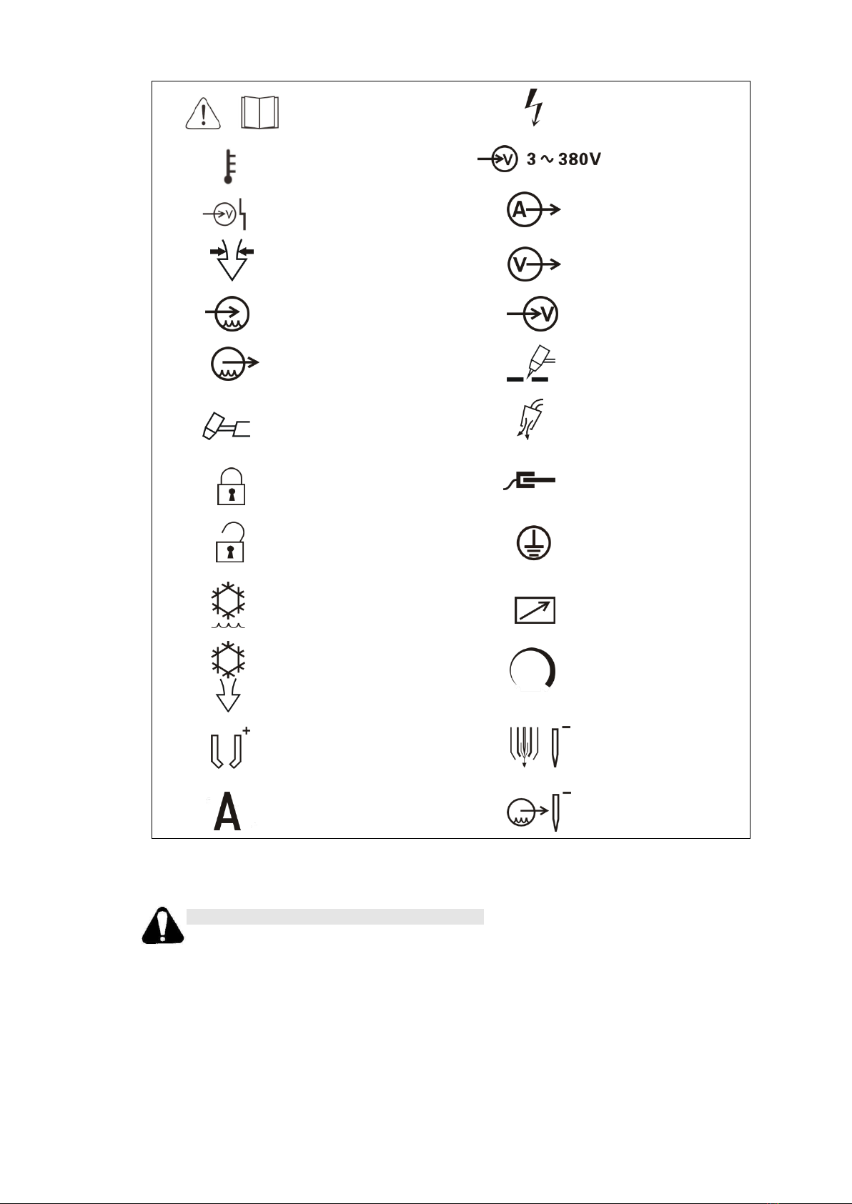
Symbol instructions.............................................................................................................6
Safety and attention ....................................................................................................................7
Working Environment Requirements .........................................................................................8
Environmental condition .....................................................................................................8
Power supply condition.......................................................................................................8
Technical parameters..................................................................................................................8
Main technical parameters...................................................................................................8
Plasma gas condition...........................................................................................................9
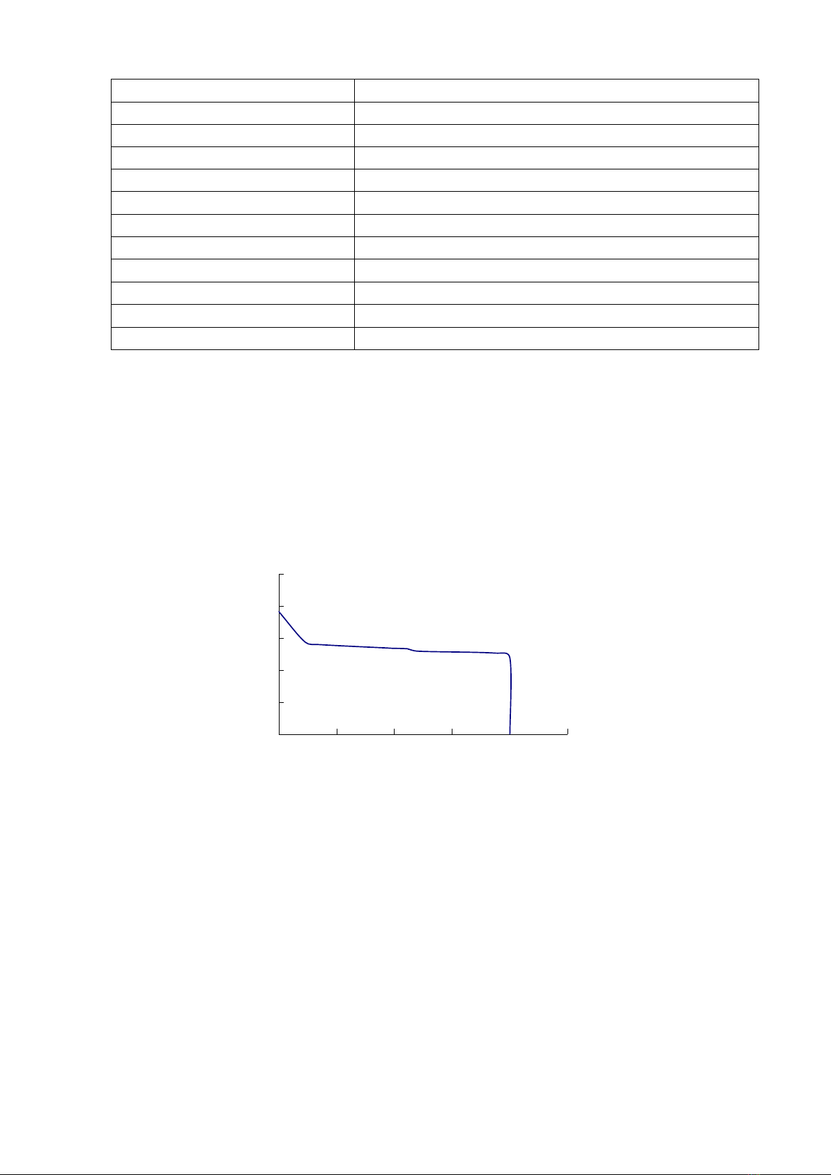
External characteristic curve ...............................................................................................9
System instruction ......................................................................................................................9
Working principles ..............................................................................................................9
Machine working theory....................................................................................................10
Installation and operation .........................................................................................................10
Moving and lifting.............................................................................................................10
Open the packing and check..............................................................................................10
The fix and installation of the plasma power source.........................................................10
The connection of three phase input cable ........................................................................11
Panel and its functions.......................................................................................................13
Protection function introduction........................................................................................14
Operation...........................................................................................................................15
Gouging operation.............................................................................................................16
Cutting operation...............................................................................................................16
Gouging technology instruction ...............................................................................................17
Cutting technology instruction .................................................................................................19
The related main technical parameters..............................................................................19
Eliminate the cutting burr..................................................................................................20
Repair and maintenance............................................................................................................21
Trouble shooting.......................................................................................................................21
Trouble shooting................................................................................................................21
Some main components sheet............................................................................................23
Packing list ...............................................................................................................................23
Attached diagram:main circuit diagram ................................................................................24

Summary
Model description
L G K -□□□ IGBT
IGBT Inverter
Rated cutting current
Air
Cutting
Plasma
Features
It has good characteristics as following:
1) It can be used for cutting and gouging both
2) This cutting machine adopts IGBT inverter technology which has high reliability and efficiency. It is light
weight.
3) Pre-set current function. Step-less adjustable cutting current, suitable for cutting various thickness work-piece.
To ensure cutting quality and save energy, low current is applied to cut thin plate, and high current is
applied to cut thick plate.
4) External and dynamic characteristics cutter are significantly better than leakage-reactance typed cutter. High success
rate in striking arc. Stable cutting current. Good arc stiffness. Clean and smooth incision. Excellent technology
performance.
5) It has the function of ascending current slowly, which can effectively extend the work life of wearing parts
and cutting torch.
6) Quite suitable for CNC automatic cutting and has all signal output which is required by CNC control.
7) The cutting current is very stable and it will not be influenced by grid voltage fluctuation.
8) 100% duty cycle. It can work continuously under max current.
9) Have over/ under voltage and phase missing protection function.
Usage
It is suitable for cutting kinds of metal materials like low carbon steel, alloy steel and non -ferrous metal
and is widely applied in the manufacturing of boiler pressure container, chemical container, industrial power
station construction, metallurgy, aerospace industry, automobiles, building an so on.
Symbol instructions
There are below symbols on this machine.

Read the manual carefully
Dangerous voltage
Over-heat
Input voltage
Power abnormal
Output current
Air pressure
Voltage output
Coolant liquid input
Voltage input
Coolant liquid output
Cutting
Plasma torch
Check gas
Lock
Ground lead
Unlock
Protection ground lead
Water cooling
Remote control
Air cooling
Increase/ Decrease
The nozzle connection of
plasma torch
Plasma gas and torch
electrode
Current
Coolant liquid and torch
electrode
Safety and attention
Please follow the notes for the safety of you and others.
It is forbidden to unfreeze the pipe line by cutting power or other usages except for cutting.
The cutter casing should ground reliably. Please make sure the grounding bolts of power ground reliably in
case of electric shock.
Cutter is the equipment with high voltage. Please wear insulated protective shield when cutting.
When exchanging torch and wearing parts, please turn off the supply power first.
Protective shield should be worn.
In order to avoid any hurt to eyes from ultraviolet radiation and strong light and to skin from spatter, please
wear protective shield according to related rules and regulations of labor protection.

It is forbidden to inhale harmful gases.
The fumes and gases produced during cutting is hazardous to health. Please wear protective shields and
install aerator according to related rules and regulations of labor protection.
Cutting cannot proceed in closed container.
The work-piece just after being cut is at high temperature. Please prevent from scald.
Protective gas cylinder and air compressor must be placed in a fixed position and prevented from collision.
Cutter and cutting place should be far away from flammable materials.
Prevent foreign bodies from entering inside the machine. And protect the cable from sharp materials.
Protect the machine from fall or collision.
In case of fall or collision, it can be used only after professional checking.
In the surface or inside of the cutting work-piece, there should be no flammable and explosive materials or
chemical materials harmful to human.
Installation and repair person must have state-authorized electrician operation certificate.
Cutting operation person should read this manual carefully and know the operation method well.
Working Environment Requirements
Environmental condition
Please use the machine in a clear place without any of dust, corrosive gas and inflammables and explosives; Do
not use it in open air and rain;
Required air relative humidity should ≤90%(at 20℃),40℃≤50%(at 40℃);
Environment temperature range should be at-10℃~40℃;
The coolant liquid cannot be frozen when use;
Any metal materials cannot be put on or insider the power source;
Keep the machine away from the wall of some other closure things at least 30cm, two machines distance at least
30cm.
Use it under altitude lower than 1000m.
Power supply condition
Power supply:3~380V/50Hz;
Voltage fluctuation range <±10%;
Frequency fluctuation range<±1%;
Unbalance rate of three phase voltage <±5%;
When use engine generator: the output power of the generator have to be 2 times higher than the rated power
of the plasma power source, with compensating coil;
Technical parameters
Main technical parameters
Item
Parameter
Rated input voltage
3~380/415V 50/60Hz
Rated input capacity
46.7kVA
Rated output current
200A
Rated output voltage
160V
Rated duty cycle
100%
Non-load voltage
315VDC

0
100
200
300
400
500
0 50 100 150 200 250
Current adjust range
40~200A
Quality cutting thickness(steel)
1~45mm
Max. cutting thickness(steel)
65mm
Plasma gas
Compressed air
Air pressure(gouging)
0.35~0.45Mpa
Air pressure(cutting)
0.45~0.6MPa
Torch cooling mode
Air/water cooling
Arc strike mode
Non-contact
Insulation grade
F
Protection grade
IP21S
Dimension mm(L×W×H)
800×380× 810
Weight
82kg
Plasma gas condition
Gas pressure range:0.5MPa~0.7MPa
Gas supply pipe compression strength:≥1MPa
Gas supply pipe inner dimension:≥Φ8
Gas flow:≥180L/min
Filter the water in the gas, then feed into the plasma
External characteristic curve
System instruction
Working principles
The control circuit of this cutting machine adopts advanced electronic part IGBT as the main inverter switch component.
Three-phase AC power is converted to 20KHz high-frequency DC current after being rectified by three phase rectifier. Then
under the function of IGBT inverter the DC current is inverted to AC high frequency current, which is inverted to DC current
after experiencing voltage reduction in high frequency transformer, current rectifying in fast recovery diode. This DC current
is filtered through reactor, and the output cutting current is obtained. Control circuit can control output current by
controlling driven pulse width. The real time cutting current, which is obtained through current sensor connected to output
terminal in series, is used as negative feedback control signal. After comparing with current adjusting signal, the negative
control signal is sent to PWM adjusting integrated circuit, then a controlled driving pulse is output to control IGBT. Thereby a
constant output current can be maintained, and a steep dropping & constant current external characteristic is obtained.
Striking arc adopts high-frequency striking model. The main circuit refers to appendix figure, and principle diagram of
control circuit is shown as below figure.
(V)
(A)

Machine working theory
Installation and operation
Moving and lifting
Power source should be shut off before moving the cutter;
The cutter bottom should be kept downwards during transportation. It is forbidden to have cutter placed
transversely or upended;
When lifting, it must be lifted vertically;
During the long-distance transportation, it must prevent the cutter from raining and moving back and forth
inside box. Shock absorption foam should be placed around cutter.
Open the packing and check
Check the machine and packing according to the packing list, of there is any damage, please try to contact the
supplier.
The fix and installation of the plasma power source
The mounting hole size of the machine
53 5
29035
φ11 65.5
45
φ8.2
7 5

The connection of three phase input cable
1) The installation have to accord with related standard, and operate by professional persons;
2) Shut off the breaker of power, the connection operation only be allowed after turning off;
3) This machine use 3 phase 380V, 50Hz, user have to prepare relevant distribution box, air breaker and power
cables. The power condition as the below sheet:
Model
The sectional area
of input copper
cable (mm2)
The sectional
area of ground
cable (mm2)
Fuse (A)
Contact capacity
(A)
LGK-200IGBT
≥16
≥16
125
125
4) The connection of power lead
Use eligible cables and sockets to connect it, and must be operated by a qualified electrician.
5) Connection of ground cable
Connect the green-yellow wire of power source cable to the ground, the sectional area must match the
requirements in above form, to ground firmly. Ground connecting method should follow state standard.
1、The connection of compressed air and the operation of pressure regulating filter (The function of pressure
regulating filter please check the below figure)
Hoop
Gas pressure
regulating valve
Inlet pipe
Draining water tip
1) The compressed gas should meet the requirement mentioned in point “Plasma gas conditions”. Connect the gas
pipe with the gas inlet of air filter on the back panel and hoop it tightly. The usage of pressure regulating filter is
as follows. When it is to adjust pressure, lift up air pressure regulating valve, and rotate it. Left rotation aims to
reduce outlet gas pressure, right rotation aims to increase outlet gas pressure. After the gas pressure is adjusted
properly, press down regulating valve.
2) The air filter regulator should be checked periodically. If the water level reaches two-thirds of filter glass, it must
be drained, or this will affect incision quality. The gas supply valve should be closed during water draining, and
Gas Checking function is selected in panel. When the indicated valve of gas pressure meter is zero, water will
drain out from drainage mouth automatically.
2. Connection of cooling water
Connect the copper nozzle marked with “water inlet” on the cutter rear side with water supply pipe, and tighten it.
Connect the copper nozzle marked with “Backwater” with water recycle pipe, and tighten it.
Notes: when use gas cooling torch, the torch selection switch on panel must be set to air-cooled torch position,
and the cooling water cannot be connected with. The cooling water is for cooling torch only, and cutter power
source does not need water cooling.
3. The connection of output terminal
1) The connection of torch
Gouging and cutting use different torch consumables, please choose the correct parts

The selection of torch nozzle
The best current range for different nozzles is different. Please select the nozzle according to below form.
Cutting nozzle:
Nozzle
(mm)
1.0
1.2
1.4
1.6
1.8
2.0
2.2
2.4
2.6
Current(A)
20~
30
30~
40
40~
65
70~
90
80~
100
110~
130
140~
170
180~
210
220~
250
Gouging nozzle:
Nozzle(mm)
2.0
2.5
3.0
Current(A)
70~120
100~140
120~180
Connection of air-cooling torch: first connect the torch cable connector M14 nut with the copper nozzle
signed with Air & Power on the front bottom panel, and screw down the nut; then connect the torch pilot
wire to terminal signed with Pilot on the front panel and screw down the nut. Finally, connect the torch
control pin to the terminal signed with Control Signal on the front panel and screw down the nut.
Special notes: it should not exceed the rated current of torch when use air cooling torch, or it will be
damaged by heat.
Connection of water-cooled torch: first connect the torch cable connector M16 nut with the copper nozzle
marked with Water& Power output on the front panel, and screw down the nut. Connect the backwater
pipe M10 nut of torch with the copper nozzle marked with Backwater on the front panel, and screw down
the nut. Connect the torch gas pipe M14 nut with the copper nozzle marked with Air& Power output and
screw down the nut. Then connect the pilot wire with the terminal marked with Pilot on the front panel,
and screw down the nut. Finally, connect the control plug of torch with the socket marked with Control
Signal, and screw down the plug nut.
The requirements on connection of control plug when customers change different torch from another
factory.
Adopt WS20J4TQ 4-core pin from WEIPU Electrical Appliance Co., Ltd
Requirements on air cooling torch connection:
a) Connect the 1, 2 pin of 4-core pin to switch control wire of cutting torch;
b) Short connect 3, 4 pin of 4-core pin by gummed wire;
c) Striking arc wire connects cold-press joint UT-8;
Requirements on water cooling torch:
a) Connect the 1, 2 pin of 4-core pin to switch control wire of cutting torch;
b) The 3, 4 pin of 4-core pin don`t connect any of wire;
c) Striking arc wire connects cold-press joint UT-8.
2) Connection of cutting ground cable
Connect the fast connector of cutting ground cable with the outlet marked with Cutting Ground cable on the
front panel and screw down it clockwise. The other end of the cutting ground cable is firmly connected to
work-piece.
4. Connection of control signal
The socket model of the connector is : WS20J7TQ, and the function for each wire pin is as following:
1) Connector pin 1 and pin 2 is signal output of success arc striking, it is one group of contact terminal of relay, and
its rated load capability is 3A/250VAC or 3A/30VDC.
2) Connector pin 3 and pin 4 is start control wire of the cutter, its starting method is controlled by operating
selection switch. Usually 2-Step is selected, that is, it starts under short connection, and stops after cutting off.
The two wire is used in parallel with torch control socket pin 1, pin 2 on the front panel.
5. The connection of water cooling machine intelligent communication interface
The socket model of the connector is : WS20J7TQ, and the function for each wire pin is as following:

1) Connector pin 1 and pin 2 is signal output of success arc striking, it is one group of contact terminal of relay, it’s
on closing status when the cutter is working, and it’s on breaking status when the cutter is not working. Its
rated load capability is 0.3A/125VAC or 1A/30VDC;
2) Connector pin 3 and pin 4 is start control wire of the cutter, it is one group of contact terminal of relay, it’s on
closing status when the torch switch is on, and it’s on breaking status when the torch switch is off. Its rated load
capability is 0.3A/125VAC or 1A/30VDC;
3) Connector pin 5 and pin 6 is protection signal that water cooling machine output to plasma cutter, when short
connect the pin 5 and 6, there will be no current and voltage output from the plasma cutter.
Panel and its functions
1) Digital ammeter: Displaying pre-set cutting current when not cutting, displaying real cutting current when
cutting;
2) Cutting current adjusting knob: Adjusting cutting current;
3) Power indicator light: Indicating if the cutter is on power
4) Air pressure indicator light:It is ON when the pressure of compressed air exceeds 0.2Mpa. It is OFF
when the pressure is less than 0.15Mpa;
5) Starting indicator light: When the light ON means the cutting machine has started ;
6) Overheating indicator light: It is ON when the cutter inside temperature is too high (Usually when the cooling fan
is damaged);
7) Power Input fault indicator light: It is ON when power source default phase or it’s power lower than 330VAC;
8) Gas control selection switch: When it’s on “Checking gas”, gas valve opens to test gas flow. When it’s on
“Cutting”, the gas valve opens during cutting automatically;
9) Torch operation mode selection switch: When it turns on 2-Step, the torch switch should be pressed at the
process of cutting, and the cutting stops after loosening the switch. When it turns on 4-Step, press the torch
switch and loosen it, the cutting starts to work, and the stops after pressing the switch again;
10) Cutting ground cable socket: To connect the cutting ground cable;
11) Torch pilot terminal: To connect torch striking wire;
12) The control socket of cutting torch: to connect the control signal wire of the cutting torch;
13) Air & Power output terminal: the current output terminal is also the compressed air output terminal. It is gas
pipe connector to connect water-cooled torch when the water-cooled torch is used, and it is connector to
connect torch gas-cooled cable when air-cooled torch is used;
14) Power switch: To control the ON/OFF of 3-phase power supply of cutter;
15) Power input: connect the 3 phase power. The green/yellow wire is the ground lead, it should be connected with
ground firmly;
16) Arc voltage output: the arc voltage output wire is not connected out of the machine, If it is needed, please open
the cutter top cover, and use two-core rubber wire to connect the wire terminal on printed board LGK7-AP5,
which has four kinds of output signal: 1:1 ,1:20, 1:50 and 1:100; Please connect the wire according to the
requirements, and pay attention to the negative and positive electrode;
17) Control signal connector: To control automatic cutting equipment (there is starting signal and arc striking success
signal);
18) Water pressure indicating light: connect the cooling water supply, when water flow is higher than 0.45L/min, the
indicator will be on;
19) Gas-cooling torch/water-cooling torch selection switch: gas-cooling torch is used only when it switches to gas
cooling, and water-cooling torch is used under water cooling mode selected;
20) Water/Power output connector: the cutting current output terminal is also the water output connector, it is used
to connect the water cooling cable;

21) Torch backwater connector: It is used to connect the water recycle pipe;
22) Water inlet connector: to connect the water outlet pipe of water cooling machine;
23) Backwater connector: to connect the backwater pipe of the water cooling machine;
24) Air pressure regulation filter:For adjusting the working pressure of compressed air and filtering the water in air;
25) The water cooling machine intelligent communication interface: this connector only be used when work with
water cooling machine;
26) Fuse holder of arc voltage signal;
27) Ground protection terminal.
28) Coolant filter: used for filtering the return coolant from the torch
29) Function selection switch: put to Gouging position for metal gouging, put to cutting position for metal cutting
控制讯号
此开关仅作保护用
请另配电源开关!
进水
回水
3~380 V
切割地线
回水水电输出气电输出
引弧控制
A试气
电源指示 气压 切割 过热 供电异常水压
L G K - 2 0 0 I G B T
I NVE RTE R A IR PL ASM A C UTT IN G M ACH INE
逆变 式 空 气等 离子 切 割机
华远焊机
NHU AYUAN WELDER
切割 电流
R
1
2
3 4 5 6
9
10
1112 13
14 1518
20 21
2 2
2 3
弧压输出
16
17
25
2 4
U0=3 15V 160V
2 00 A
40A/96V-200A/160V
U1=380V
100%
3~
f
2
f
1
I2
X
U2
3~5 0 /6 0 H z
防 护等 级:I P 2 1 S 绝缘 等级 :F冷却 方式 :风 冷
GB /T 15 57 9. 1- 20 13
型号:LGK-200 IGBT
制造商:成都华远电器设备有限公司
地 址 : 成 都 双 流 西 南 航 空 港 经 济 开 发 区 空 港 二 路
1299
号
地 址 : 成 都 市 武 侯 科 技 园 武 兴 四 路
5
号
生产厂:成都华远电器设备有限公司
名称:逆变式空气等离子切割机
出厂编号:
I1max =71 A I1eff =7 1A
重量:82kg
(建议间隔时间不超过6个月或300个弧小时)
请 定 期 清 洗 或 更 换 过 滤 器
1、观察到筒体内或过滤网上的杂质较多时,可
通过打开过滤器下部的排污阀,自动清洗排
出杂质。
2、当自动清洗不能排出钳在滤网上的杂质时,
拆下透明筒体取出滤网组件,然后对滤网
进行清洗。
注意:不能损坏滤网,必要时请更换滤网组件。
28
自动水冷割炬
气冷割炬自 锁
非 自锁
切割
气刨
8
19
7
29
Protection function introduction
1) Air pressure protection
When the indicated value of the pressure meter, which is fixed on the back of the cutter, is lower than 0.2
MPa, the protection circuit starts working and the cutter cannot start;
When the indicated value is lower than 0.15 MPa during cutting, the cutting arc will extinguish;
Note: When adjust the air pressure, the panel function must be set to ‘checking gas’!
2) Water pressure protection
When the water supply is lower than 0.45L/min, protection circuit starts working and cutter cannot start;
When the water supply is lower than 0.4L/min during the process, protection circuit starts working and
cutting arc extinguishes automatically;
3) Over-heat protection
When the ambient temperature is too high or the cooling fan is broken, the cutter will be over heated
under the rated current, and heat protection circuit starts working, the cutting arc will extinguish
automatically;
4) Abnormal power supply protection
When 3 phases power supply misses phase, protection circuit starts working and there is no arc striking;
When 3 phrase power supply is lower than 330VAC, protection circuit starts working and there is no arc

striking;
Note: the water and air pressure protection function is for protecting the torch only!
5) Notes of anti-interference (Specially pay attention when work on CNC automatic cutting equipment)
Cover the whole torch cable (from torch holder to output terminal ) of the cutter with shielding layer, the
shielding layer should be metal hose or shielding net pipe made of aluminum or copper, metal materials
which is magnetic conducted cannot be used, the shielding layer don't need to connect with ground;
All the control lines which connected with plasma power source should be shielding wire, the shielding
layer should be connected ground well;
The control system of CNC cutting machine should be away from the cutting table, torch cables and cutting
torch head, especially the cutting torch heard. When striking arc, the high frequency spark arc on the
cutting torch head may produce strong space spreading high frequency disturb signal, which may crash the
control system;
There should be shields on the controller of CNC system, and the shielding layers should be ground
connected well;
All the lines connected with CNC controller and cutting table should be shielding wire (Such as the control
wire of step motor ,limit switch etc.), and the shielding layers should be ground connected well;
The pile of the ground cable should be connected with ground well.
Operation
1) Safety notes
Notes:
Operation strictly accordant with the following steps
Notice
Electric shock may hurt or
even kill man.
Cutting may cause fire or explosion
(Splashes may ignite flammable materials nearby.
Those materials should be 10m away from the
working place.
(Shut off the power during connection
(Do not touch the conducted parts
Fume & dust is harmful.
(Do not breathe in the fume and dust
caused by cutting
(Clean up the oil spot on work piece.
(Keep fresh air in working place
(Fume extraction equipment should be
prepared.
Arc may hurt your eyes and skin.
(Strong arc may hurt your eyes.
(Ultraviolet radiation generated by arc may hurt skin
and eyes. Please wear shielded guard when cutting.
Overheated part may hurt your skin.
(Do not touch the overheated part on
the work piece.
(Do not touch hot cable or torch just by
hands.
Fast moving thing may injure you.
(Do not put your hands or other things into the fan
shield.
(Cover the opened case shell well during cutting
operation.
In case of injury for your skin and eyes, please wear required guards
according to Labor Security and Hygiene rules. Electrode and nozzle should
be replaced only after the cutter is power off.
Operation should proceed according to related Labor and Security
regulations.

2) Turn on the power switch after installation and connection. Then the power indicator lamp is ON; If the gas
pressure is less than 0.25Mpa, the lamp will be OFF, then the gas supply should be checked;
3) Start water supply equipment. The indicator lamp of water pressure on panel is ON when opens water supply
valve.
4) Place the gas control switch to “Check Gas”, adjust the Adjusting knob of air filter regulator to make the output
pressure and flux fit cutting condition. After adjusting, place the knob on “Cutting” position. Select panel
operation method and control switch point. At 2-Step point, the torch switch; should be pressed all the time
during cutting. After loosening, the cutting comes to stop. At 4-Step point, press the torch switch and then
loosen it, and cutting can start. User can make selection according to his operation habit;
5) Checking the panel indicator lamps. The indicator lamps status, under which cutting can be operated, is shown
as following sheet.
Indicator
Power
Cutting
Gas
pressure
Water
pressure
Overheated
Supply
abnormal
Status
ON
OFF
ON
ON
OFF
OFF
Notes: water pressure indicator will be OFF when gas-cooled torch is applied on machine
Gouging operation
1) Set the function selection switch on panel to Gouging position
2) Set the basic distance from nozzle to workpiece 3mm, angle αto 35°
3) Gouging under 2-step
a) Press the torch switch without loose, air come out from the nozzle, start indicator on, HF start, arc pilot
b) Move the arc to workpiece, keep nozzle axle and workpiece angle, move torch with the gouging direction
c) Loose the torch switch, gouging stop, air continue come out from the nozzle for 7S
4) Gouging under 4-step
a) Press the torch switch then loose, air come out from the nozzle, start indicator on, HF start, arc pilot
b) Move the arc to workpiece, keep nozzle axle and workpiece angle, move torch with the gouging direction
c) Press the torch switch, gouging stop, air continue come out from the nozzle for 7S
5) Warning
a) For different gouging size, it need to adjust the nozzle axle and workpiece angle, but should within 30°~
45°,exact method refer to the gouging surface adjust method and gouging parameter table
b) For different gouging size, it need to adjust the nozzle and workpiece distance, exact method refer the gouging
surface adjust method, the distance to small will increase the nozzle damage
c) Normally the electrode life time is shorter than the nozzle during gouging, before operate need check the
electrode and replace it when necessary
Cutting operation
1) Keep the torch nozzle 2mm~ 5mm away from work-piece. The axis line of nozzle should be perpendicular to
work-piece, and starts cutting from the edge of work-piece. When the plate thickness is ≤12mm, a hole can be
drilled on work-piece and then cutting can be started around the hole. The cutting torch should inclined to one
side a little during drilling a hole on work-piece, so that the molten metal can be blown away easily. To drill a
hole by use of plasma arc is not proposed, because this will damage nozzle easily, it is better to drill a hole in arc
striking point first, then strikes arc on the edge of hole. Press down torch switch, compressed gas sprays out from
nozzle, and cutting indicating lamp is ON. After gas pre-flows for 1 to 2 seconds, high frequency is generated, arc
is stroke, and cutting begins by moving torch;
2) When the control switch of operation method on front panel is at 2-Step point, press down the torch switch and
cutting starts after arc striking. After loosening the switch, there is no voltage output, and cutting ends, and

compressed gas stops supply in 15 seconds. When it is at 4-Step point, press down the switch and loosen it, and
cutting starts after arc striking automatically. Press the switch again or press it till the arc is off, then there is no
voltage output, cutting ends, and compressed gas stops supply in 15 seconds.
Gouging technology instruction
1、Basic parameter:
Item
Instruction
Parameter
Angle α
Angle between nozzle axle and workpiece plate
30~45°
Basic distance
From nozzle to workpiece
0.5~10mm
Move speed
Gouging torch move speed
200~2000mm/min
Angle β
Angle between torch and torch move position
0°±5°
2、Gouging surface
3、Method for gouging surface adjustment
According to the exact requirements, the gouging surface parameter can be adjusted:
1) Increase the torch move speed can reduce the gouging width and depth
2) Reduce the torch move speed can increase the gouging width and depth
3) Increase the basic distance can increase the gouging width and reduce the depth
4) Reduce the basic distance can reduce the gouging width and increase the depth
5) Increase the angleαcan reduce the gouging width and increase the depth
6) Reduce the angleαcan increase the gouging width and reduce the depth
7) Increase the current can increase the gouging width and depth
8) Reduce the current can reduce the gouging width and depth
9) ncrease the nozzle size can reduce the gouging depth and increase the width

4、Gouging surface parameter setting
Following are the gouging parameter for low carbon steel for reference
Current
(A)
Nozzle
(mm)
Air pressure
(Mpa)
Air flow
(L/min)
Basic distance
(mm)
Angleα
(°)
Move speed
(mm/min)
Thickness
(mm)
Width
(mm)
180
φ3.0
0.4
140
6
35
750
9.1
13.2
1000
8.1
11.4
1250
6.1
11.6
40
750
9.8
11.5
1000
8.6
9.8
1250
7.0
9.7
160
35
500
8.2
13.1
750
6.6
11.9
1000
5.3
11.2
1250
4.9
9.8
40
750
8.8
10.2
1000
6.8
11.4
1250
5.8
9.8
140
φ2.5
0.4
130
3
35
750
8.0
12.6
1000
6.7
12.0
1250
5.7
10.1
120
35
750
5.7
9.8
1000
4.6
9.2
1250
3.9
8.8
120
φ2.0
0.4
120
3
30
1000
5.8
10.8
1250
4.9
9.3
35
1000
5.0
9.5
1250
4.5
8.4
40
1000
6.3
8.7
1250
5.7
8.1
Customer need adjust the real parameter according to the exact gouging requirements to get best performance
5、Angleβaffect the gouging surface
This angle βvalue be is 0°the best, that means the nozzle center and gouging seam center coincide. The
angle βincrease will cause gouging surface quality not good, and slag will stick on the gouging seam
6、The spatter retro-reflection
The spatter retro-reflection with the torch move direction during gouging, this is caused by the angel αtoo
big, can reduce the angle αto avoid the retro-reflection
7、Electrode ageing
Followed by the electrode ageing, the gouging surface size will reduce slowly. At this time, increase the
gouging current can improve a little, but in order to ensure the gouging surface quality, please replace the ageing
electrode on time.
8、The gas affects the gouging groove surface
Air, N2, Ar/H5 can be used for the plasma gas
1) Air is the cheapest gas which can get acceptable gouging groove surface on carbon steel, stainless steel and

aluminum
2) N2 can lengthen the gouging parts life time, and get acceptable gouging groove surface on carbon steel
and stainless steel
3) Ar/H5 mixed gas can get best metal remove without slag on the gouging surface. It can get clear and
smooth quality on aluminum and stainless steel gouging groove surface
Cutting technology instruction
The related main technical parameters
1) Cutting material and thickness
The selection of cutting technical parameters is based on the cutting material and thickness. If the material is thick,
it should adopt large current and nozzle with big aperture. For different material under the same thickness, the
parameter should also be different.
2) Nozzle selection
The three main dimension of nozzle are the diameter of nozzleφ, the hole pass length ι and the compacted angle α,
they all can affect the cutting. There should be a certain proportion between ι and φ, the value is usually lower than 2,
and it usually takes
, the compact angle usually takes α=30°~60°, and now it usually takes α=30°.
3) Cutting current and arc voltage
The selection of cutting current should be according to the diameter of the nozzle, the relationship between the
two should be as: I(current A)=(70~100)×φ(mm). As the increase of the metal thickness, the influence of arc current
to the cutting speed will become less. But as the increase of current, the burning damage will be worse for the
electrode and the nozzle. So when cutting a thick metal work-piece, usually the increase of cutting speed is made by
increasing arc voltage. The actual arc voltage is decided not only by the gas type but also by the air flux and nozzle
shape. Working voltage increases with the increase of gas flux.
4) Gas flow Q
The arc voltage increases as the increase of air flow, that is, the arc power, the cutting speed, as well as the cutting
capacity and quality is improved accordingly. Because the arc compression level increases, the energy is more
concentrated, the arc beam temperature, the arc spraying speed, as well as the arc current impulsion increases. But
overlarge current may cause the instability of the plasma arc. Usually no change is made to air flow for one torch. But
it can be adjusted a little when the cutting torch or cutting thickness is different.
5) Electrode inner contraction ΔLy
When electrode inner contraction ΔLy is so small that electrode extends into spray hole, electrode is damaged
seriously by air flow impact and the combination function between high temperature gas and electrode. This leads to
the instability of plasma arc, weak compression effect, and weak cutting penetration ability that cutting cannot be
proceeded. If ΔLy is too big, the arc is so unstable that the cutting ability is weakened. The electrode end should be
placed within siphoning zone of gas current under a relative vacuum condition, and it will difficult to damage
electrode by burning, as well as this is beneficial for compression of arc. ΔLyis about 2-4mm.
6) The distance between the nozzle and the work-piece (d)
If the d is too big, the blow power of plasma arc for molten metal decreases, so does the cutting ability, and the
burr on the bottom increases, meanwhile the instability of the arc increases. However, if the d is too small, it increases
the possibility of short circuit between the nozzle and the work-piece. Usually d should be as small as possible on
condition that no short circuit is caused between nozzle and work-piece. The d under normal cutting of air plasma is
usually 2~5mm. The work-piece can also contact with the nozzle during air plasma cutting, that is, the nozzle glide on
the surface of the work-piece. This cutting method is called contact cutting, and the cutting thickness is the half as the
ordinary cutting.
7) Open circuit voltage
Table of contents
Other HUAYUAN Cutter manuals