manuals.online logo
Brands
  1. Home
  2. •
  3. Brands
  4. •
  5. Hubbell
  6. •
  7. Controllers
  8. •
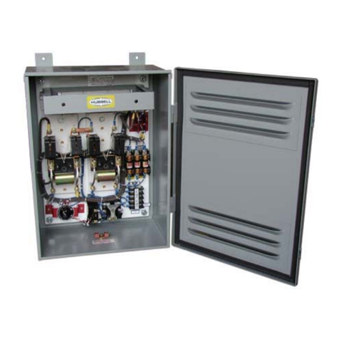
  9. Hubbell HBL1372D User manual

Hubbell HBL1372D User manual

English Français Español
PD2018 (Page 1) PRINTED IN U.S.A. 5/06
Hubbell Incorporated (Delaware)
185 Plains Road
Milford, CT 06460-8897
1-800-323-2792
Installation Instructions Notice de montage Instrucciones de instalación
MANUAL MOTOR CONTROLLERS
WITHOUTOVERLOADPROTECTION
SUITABLEAS MOTOR DISCONNECT
30A, 40A, 50A, 60A, & 85A 600 VAC
COMMANDE MANUELLE DE MOTEUR SANS
PROTECTION DE SURCHARGE
CONVIENT COMME SECTIONNEUR DE MOTEUR
30A, 40A, 60A, et 85A 600 V, CA 30A, 40A, 60A, y 85A V~600
GENERALINFORMATION
1. NOTICE: For installation by a qualified electrician in accordance
with national and local electrical codes and the following instructions.
2. CAUTION:RISKOFELECTRICSHOCK.Disconnectpowerbefore
installing. Never wire energized electrical components.
3. CAUTION:USECOPPERCONDUCTORSONLY.
4. DONOTTINCONDUCTORS.
5. Check that device’s type and rating are suitable for the application.
6. Separate overcurrent protection must be provided in accordance
with National Electrical Code®Article 220 or Canadian Electrical
Code Section B as appropriate.
7. Suitable for use as a motor controller on a circuit capable of
providing not more than 10,000 Symmetrical Amperes, 600 VAC
max., when protected by RK5 class fuses.
8. Suitable for use as a motor disconnect on a circuit capable
of providing not more than 10,000 Symmetrical Amperes, 600
VAC max., when protected by fuses as marked on the
controller.
GENERALWIRINGINSTRUCTIONS
1. Select conductors having 90º C or higher rated insulation having
sufficient ampacity in accordance with the 60º C column (for 30A,
40A and 60A motor controllers ) and 75º C column ( for the 50A
and 85A motor controllers) of National Electrical Code®Table
310-16 or Canadian Electrical Code Table 2.
2. Strip conductors per Table on reverse side.
3. Loosen terminal screws. Connect conductors to proper terminals.
See diagram on switch body, Fig. 1,Fig. 3 and Table (reverse side).
4. TAKECAUTIONTHATTHEREARENO STRAYWIRESTRANDS.
5. Tighten screws per Table on reverse side.
ENCLOSUREINFORMATION
1. The enclosures include a lockout provision for a suitable padlock
lockout device to isolate energy from the connected equipment as
a method of compliance to OSHA Lockout/Tagout regulation 29
CFR Part 1910.147. Min. 3/16" dia. hasp to be used. This Feature
does NOT isolate the power supplied to the enclosure during
internal servicing of the enclosure.
2. Any unused conduit entrances must be sealed with Listed/Certified
closure plugs.
3. Type 1 enclosure may be mounted for top, bottom or back conduit
entrances.
4. Form condensate Drip Loops as shown in Fig. 2 when TOP conduit
entrance is used.
5. Type 3R enclosure may be mounted for bottom or back conduit
entrances for the aluminum sheet enclosure. and top, bottom
or back for metal frame enclosure.
6. Type 3 non-metallic enclosure may be mounted for top and
bottom conduit entrances. For a 3R environment a drainhole
must be drilled for water drainage.
ENCLOSUREINSTALLATIONINSTRUCTIONS
1. Remove cover and mount frame or enclosure using mounting
holes on back of frame or enclosure.
RENSEIGNEMENTSGÉNÉRAUX
1. AVIS - Doit être installé par un électricien qualifié conformément aux
codes de l’électricité nationaux et locaux et selon les directives suivantes.
2. ATTENTION-RISQUEDECHOCÉLECTRIQUE.Débrancherlecircuitavantdeprocéder
au montage. Ne jamais câbler des composants électriques dans un circuit sous
tension.
3. ATTENTION-EMPLOYERUNIQUEMENTDESCONDUCTEURSENCUIVRE.
4. NEPASÉTAMERLESCONDUCTEURS.
5. S’assurer que le type et les caractéristiques nominales de ce dispositif conviennent à
l’application.
6. AVIS - Un dispositif séparé de protection contre les surintensités doit être fourni
conformément à la section B du Code canadien de l’électricité.
7. Convient à l’emploi dans un circuit dont la capacité en court-circuit est inférieure à
10,000 ampères efficaces symétriques à un maximum de 600 V CA, lorsque protégé par
un fusible de classe RK5.
8. Convient comme sectionneur de moteur dans un circuit dont la capacité en
court-circuit est d’au plus 10 000 ampères symétriques, à 600 VCA max.,
lorsque protégé par les fusibles indiqués sur la commande.
DIRECTIVESGÉNÉRALESDECÂBLAGE
1. Choisir des conducteurs dont l’isolant a une résistance thermique de 90ºC ou
plus et de capacité de courant admissible suffisante selon la colonne de 60ºC
(pour commandes de moteurs de 30 A, 40 A et 60 A) et la colonne de 75ºC
(pour les commandes de moteurs de 50 A et 85 A) du Tableau 2 du Code
canadien de l’électricité.
2. Dénuder les conducteurs selon les indications du Tableau au verso,
3. Desserrer les vis de borne. Raccorder les conducteurs aux bornes appropriées.
Consulter la Fig. 1, Fig. 3 et le Tableau (verso).
4. S’ASSURERQUETOUSLESBRINSSONT BIEN INSÉRÉS.
5. Serrer les vis de borne selon les indications du Tableau au verso..
RENSEIGNEMENTSSURLESBOÎTIERS
1. Ce boîtier offre une possibilité de blocage au moyen d’un dispositif à cadenas pour
isoler les appareils qui y sont branchés, conformément aux exigences du règlement
OSHA 29 CFR, section 1910.147 en matière de blocage et d’étiquetage. Utiliser un
moraillon d'un diam. min de 5 mm. Cependant, cette disposition N’ISOLE PAS le boîtier
de sa source d’alimentation pour les fins de maintenance interne de celui-ci.
2. Toute ouverture d’arrivée de conduit inutilisée doit être scellée au moyen d’un obturateur
homologué.
3. Le boîtier de type 1 peut être monté pour des arrivées de conduit par le haut, par le bas
ou par l’arrière.
4. Dans le cas d’une arrivée de conduit par le HAUT, former des boucles d’égouttement tel
qu’illustré à la Fig. 2.
5. Le boîtier de type 3R peut être monté pour des arrivées de conduit par le bas
ou par l’arrière dans le cas d’un boîtier en aluminium et par le haut, le bas ou
l’arrière pour un boîtier en métal coulé.
6. Le boîtier non métallique de type 3 peut être monté pour des arrivées de
conduit par le haut et le bas. Dans un environnement 3R, percer un trou pour
l’écoulement de l’eau.
MÉTHODEDEMONTAGEDESBOÎTIERS
1. Retirer le couvercle et fixer le bâti ou le boîtier au moyen des trous dans l’arrière du bâti
ou du boîtier.
2. Percer des trous ou retirer les débouchures aux endroits nécessaires. Choisir
les raccords d’entrée de conduit ou de câble appropriés et les fixer au bâti ou
au boîtier. Toute ouverture d’arrivée de conduit inutilisée doit être scellée avec
un obturateur et du mastic de calfeutrage.
INFORMACIÓNGENERAL
1. AVISO - Para ser instalado por un electricista calificado, de acuerdo
con los códigos eléctricos nacionales y locales, y siguiendo estas instrucciones.
2. CUIDADO-RIESGODECHOQUEELÉCTRICO.Desconectarlacorrienteantesde
la instalación. No conectar nunca componentes eléctricos en un circuito
energizado.
3. CUIDADO-UTILIZARSOLAMENTECONDUCTORESDECOBRE.
4. NOESTAÑARLOSCONDUCTORES.
5. Asegurarse de que el tipo y las características nominales del dispositivo sean
apropiados para la aplicación.
6. AVISO - Debe proporcionarse un dispositivo protector contra sobrecorriente por
separado, conforme al artículo 220 de la Norma oficial mexicana NOM-001-SEMP.
7. Puede utilizarse en un circuito capaz de suministrar hasta 10 000 amperes efectivos
simétricos a 600 V CA como máximo, cuando protegido por fusibles de clase
RK5.
8. Puede utilizarse como desconectador de motor en un circuito capaz de
suministrar hasta 10 000 amperes efectivos simétricos, a 600 V CA
comomáximo, cuando esté protegido por fusibles como los marcados en
el desconectador.
INSTRUCCIONESGENERALESDECABLEADO
1. Elegir calibres de conductores con una resistencia de aislamiento de
90º C o más y de capacidad de corriente suficiente según la columna de
60º C (para desconectadores de motores de 30A, 40A y 60A) y la columna
de 75º C ( para desconectadores de motores de 50A y 85A) de la tabla
400-5 de la Norma oficial mexicana NOM-001-SEMP.
2. Pelar los conductores como se muestra en la Tabla al dorso.
3. Aflojar los tornillos de los bornes. Conectar los conductores a los bornes
apropiados. Ver la Figura 1, Figura 3 y la Tabla (dorso).
4. ASEGURARSEDEQUENOQUEDENHILOSSUELTOS.
5. La caja de tipo 3R puede montarse para entradas de conducto por debajo
o por detrás si se trata de cajas de aluminio y por arriba, por debajo o por
detrás si se trata de cajas de fundición.
INFORMACIÓNSOBRELACAJA
1. Esta caja ofrece una posibilidad de bloqueo con un dispositivo apropiado de traba
con candado para aislar los equipos conectados a la misma, a fin de dar
cumplimiento a la norma OSHA 29 CFR, parte 1910.147 en materia de bloqueo y
etiquetado. Utilizar un pasador con un diám. min. de 5 mm. Sin embargo, esta
característica NO AISLA la caja de su fuente de alimentación a los fines del
mantenimiento interno de la misma.
2. Toda entrada de conducto que no se utilice debe sellarse con obturadores
homologados.
3. La caja de tipo 1 puede montarse para entradas de conducto por arriba, por
debajo o por detrás.
4. Cuando se use la entrada de conducto por ARRIBA, formar lazos de goteo como
se muestra en la Fig. 2.
5. La caja de tipo 3R puede montarse SOLAMENTE para entradas de conducto por
debajo o por detrás.
6. La caja no metálica de tipo 3 puede montarse para entradas de conducto
por arriba y por debajo. En un entorno 3R debe taladrarse un orificio de
drenaje para purgar el agua.
INSTRUCCIONESDEINSTALACIÓNDELACAJA
1. Quitar la tapa y montar el bastidor o la caja usando los orificios de fijación en el
dorso del bastidor o de la caja.
DESCONECTADOR MANUAL DE MOTOR SIN
MOTOR PROTECCIÓN DE SOBRECARGAPUEDE
USARSE COMO DESCONECTADOR DE
PD2018 (Page 2) PRINTED IN U.S.A. 5/06
Hubbell Incorporated (Delaware)
185 Plains Road
Milford, CT 06460-8897
1-800-323-2792
HUBBELL DE MÉXICO garantiza este producto, de estar libre
de defectos en materiales y mano de obra por un año a partir de
su compra. Hubbell reparará o reemplazará el artículo a su juicio
en un plazo de 60 días. Esta garantía no cubre desgastes por
uso normal o daños ocasionados por accidente, mal uso, abuso
o negligencia. El vendedor no otorga otras garantías y excluye
expresamente daños incidentales o consecuenciales inherentes
a su uso. Esta garantia es válida sólo en México.
HUBBELL DE MÉXlCO, S.A. DE C.V.
Av. Coyoacán # 1051 Tel.:(5)575 - 2022
México, D.F. 03100 FAX: (5)559 - 8626
2. Drill holes or Remove knockouts at desired locations. Select appropriate
conduit/cable entry fittings as required and assemble to frame or enclosure.
Seal all unused outlets with provided plugs using sealing compound.
3. Wire enclosure controller according to General Wiring Instructions.
4. NOTICE: Green Grounding wire in conduit/cable MUST be
connected to GREEN grounding screw or grounding terminal marked GR.
5. Mount controller with toggle in OFF position and positioned as follows:
• Type 1, 3R metal frame and type 3 non-metallic enclosure: toggle pointing
DOWN.
• Type 3R aluminum sheet enclosure: toggle pointing TO THE RIGHT.
6. Secure controller with mounting screws provided.
7. Install cover as follows:
• Type 1 enclosure: secure with cover mounting screws.
• Type 3 non-metallic: use provided gasket. Attach cover to base as follow:
Cover handle must be in “off “ position to match switch toggle in “off”
position. Secure cover with mtg. screws. Type 3R metal frame: use
provided gasket. Secure cover with mtg. screws Type 3R aluminum
enclosure: ensure that controller toggle and RED lever are in the “OFF”
position. See inside label from 3R enclosures.
8. Secure cover with screws. Operate RED lever. (SHOULD
MOVE FREELY).
English
Fig. 2
Drip Loops
Boucles d'égouttement
Lazos de goteo
Français Español
3. Raccorder les conducteurs à la commande manuelle conformément aux
Directives générales de câblage.
4. AVIS - Il est OBLIGATOIRE de raccorder le fil de mise à la terre vert du conduit ou
du câble à la vis VERTE de MALT ou à la borne de MALT identifiée par les lettres
GR.
5. Monter la commande manuelle en s’assurant que la bascule est en position
«OFF» et orientée de la façon suivante :
• Type 1, boîtiers de type 3R métallique et non métallique : la bascule pointant
vers le BAS.
• Boîtier de type 3R en aluminium: la bascule pointant vers la DROITE.
6. Fixer la commande manuelle à l’aide des vis fournies.
7. Fixer le couvercle comme suit :
• Boîtier de type 1 : utiliser les vis de fixation du couvercle.
• Type 3 non-métallique: utiliser le joint fourni. Fixer le couvercle sur la
base comme suit : la bascule du couvercle doit être à «off» et correspondre
à la position de la bascule de la commande soit «off». Fixer le couvercle
avec les vis. Boîtier de type 3R métallique : utiliser le joint fourni. Fixer le
couvercle avec les vis. Boîtier de type 3R en aluminium : s’assurer que la
bascule de la commande manuelle et le levier ROUGE sont en position «OFF».
Consulter l’étiquette à l’intérieur du boîtier 3R.
8. Fixer le couvercle avec les vis. Actionner le levier ROUGE. (IL DEVRAIT SE
DÉPLACER LIBREMENT.)
2. Taladrar orificios o quitar los discos removibles en los sitios que se
desee. Elegir los accesorios apropiados para las entradas de conducto o
de cable que sean necesarios y unirlos al bastidor o a la caja. Sellar todas
las salidas no utilizadas con los tapones provistos, aplicando un
compuesto sellador.
3. Cablear el desconectador de motor según las Instrucciones generales de cableado.
4. AVISO - El hilo verde de conexión a tierra en el conducto o el cable DEBE conectarse
al tornillo VERDE de conexión a tierra o al borne de conexión a tierra marcado GR.
5. Montar el desconectador de motor con la palanca en posición “OFF” y
colocada del modo siguiente: • Caja de tipo 1, caja de fundición de tipo 3R
y caja no metálica de tipo 3: palanca apuntando hacia ABAJO. • Caja de
aluminio de tipo 3R: palanca apuntando hacia LA DERECHA.
6. Fijar el desconectador de motor con los tornillos de fijación provistos.
7. Instalar la tapa del modo siguiente: • Caja de tipo 1: fijarla con los tornillos
de fijación de la tapa. Caja no metálica de tipo 3: usar la junta provista.
Unir la tapa a la base del modo siguiente: La palanca de la tapa debe
estar en posición “off “ para coincidir con la palanca del desconectador en
posición “off”. Fijar la tapa con tornillos de fijación. Caja de fundición de
tipo 3R: usar la junta provista. Fijar la tapa con tornillos de fijación. Caja
de aluminio de tipo 3R: asegurarse de que la palanca del desconectador
de motor y la palanca ROJA estén en la posición “OFF”. Ver la etiqueta
interior en las cajas 3R.
8. Fijar la tapa con tornillos. Accionar la palanca ROJA. (DEBERÍA MOVERSE
LIBREMENTE).
Fig. 3
A = Cat # • Nº de réf. • Núm. de cat.
B = Hole Size • Calibre trou • Calibre agujero
C = Conduit Size • Calibre de conduit • Calibre del conducto
D = "GR Hub Size • Calibre écrou «GR» • Calibre tuerca «GR»
Reference Conduit Information
Information du conduit
Información para conducto
HBL13R22D
HBL13R23D
7/8
22.2mm
1 1/8
28.5mm
RACO
1702/1703 RACO
1242/1243
RACO
1242/1243
RACO
1702/1703
ABC D
Fig. 1
Back Wired
Câblage arrière
Cableado posterior
Side Wired
Câblage latéral
Cableado lateral
Single phase - connect wires
in series for double break.
Monophasé – câbler pour
double coupure en série.
Monofásico – conectar los
cables para doble ruptura en
serie. HBL1372D
HBL1379D HBL1392D
HBL1389D HBL13R22D
HBL13R23D HBL13R92D
HBL13R89D HBL16R92D
HBL16R93D
HBL13R12D
HBL13R13D
CHARGE
CARGA

This manual suits for next models

11

Other Hubbell Controllers manuals

Hubbell Euclid Lifting Magnet Controller 4295 User manual

Hubbell

Hubbell Euclid Lifting Magnet Controller 4295 User manual

Hubbell Reversing-Plugging Control 4010 User manual

Hubbell

Hubbell Reversing-Plugging Control 4010 User manual

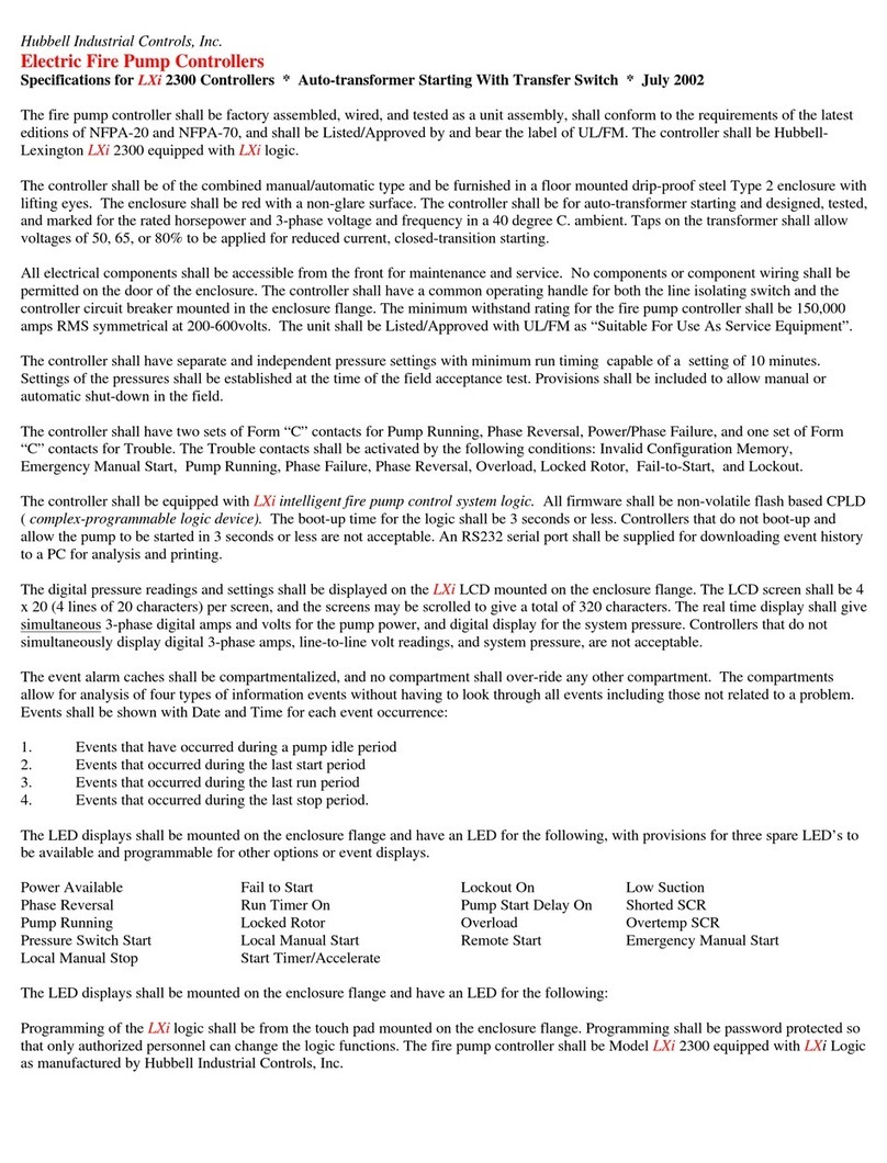
Hubbell LXi-2300 User manual

Hubbell

Hubbell LXi-2300 User manual

Hubbell CHANCE BPRS User manual

Hubbell

Hubbell CHANCE BPRS User manual

Hubbell Electric Fire Pump Controllers LXi 2200 User manual

Hubbell

Hubbell Electric Fire Pump Controllers LXi 2200 User manual

Hubbell Electric Fire Pump Controllers LXi 2900 User manual

Hubbell

Hubbell Electric Fire Pump Controllers LXi 2900 User manual

Hubbell Chance CRS User manual

Hubbell

Hubbell Chance CRS User manual

Hubbell Euclid Lifting Magnet Controller 4291 User manual

Hubbell

Hubbell Euclid Lifting Magnet Controller 4291 User manual

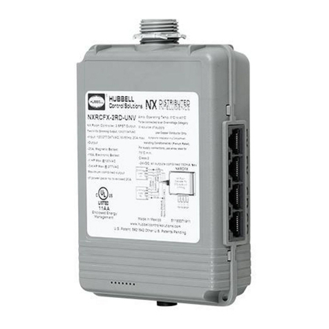
Hubbell NX Distributed Intelligence NXRCFX Series User manual

Hubbell

Hubbell NX Distributed Intelligence NXRCFX Series User manual

Hubbell GAI-Tronics HUBBCOM GSC1100 User manual

Hubbell

Hubbell GAI-Tronics HUBBCOM GSC1100 User manual

Hubbell LXi-1100 User manual

Hubbell

Hubbell LXi-1100 User manual

Hubbell Electric Fire Pump Controllers LXi-1200 User manual

Hubbell

Hubbell Electric Fire Pump Controllers LXi-1200 User manual

Hubbell Diesel Engine Fire Pump Controller LX3000 User manual

Hubbell

Hubbell Diesel Engine Fire Pump Controller LX3000 User manual

Hubbell Electric Fire Pump Controllers LXi 1900 User manual

Hubbell

Hubbell Electric Fire Pump Controllers LXi 1900 User manual

Hubbell Electric Fire Pump Controllers LXi 1800 User manual

Hubbell

Hubbell Electric Fire Pump Controllers LXi 1800 User manual

Hubbell NX Distributed Intelligence Room Controller User manual

Hubbell

Hubbell NX Distributed Intelligence Room Controller User manual

Hubbell Electric Fire Pump Controllers LXi-2700 User manual

Hubbell

Hubbell Electric Fire Pump Controllers LXi-2700 User manual

Hubbell GAI-Tronics HUBBCOM GSC3100 User manual

Hubbell

Hubbell GAI-Tronics HUBBCOM GSC3100 User manual

Hubbell Electric Fire Pump Controllers LXi 2100 User manual

Hubbell

Hubbell Electric Fire Pump Controllers LXi 2100 User manual

Hubbell Silicon Controlled Rectifier 4922c User manual

Hubbell

Hubbell Silicon Controlled Rectifier 4922c User manual

Hubbell CHANCE User manual

Hubbell

Hubbell CHANCE User manual

Hubbell Electric Fire Pump Controllers LXi 1300 User manual

Hubbell

Hubbell Electric Fire Pump Controllers LXi 1300 User manual

Hubbell Electric Fire Pump Controllers LXi 1400 User manual

Hubbell

Hubbell Electric Fire Pump Controllers LXi 1400 User manual

Hubbell Electric Fire Pump Controllers LXi-2400 User manual

Hubbell

Hubbell Electric Fire Pump Controllers LXi-2400 User manual

Popular Controllers manuals by other brands

Hanna Instruments HI 8001 instruction manual

Hanna Instruments

Hanna Instruments HI 8001 instruction manual

Monoprice RVC25-70 Quick install guide

Monoprice

Monoprice RVC25-70 Quick install guide

CARLO GAVAZZI RSBT Series troubleshooting guide

CARLO GAVAZZI

CARLO GAVAZZI RSBT Series troubleshooting guide

E-T-A EtherNetIP ControlPlex CPC12EN quick start guide

E-T-A

E-T-A EtherNetIP ControlPlex CPC12EN quick start guide

Uponor Smatrix Move PRO Installation and operation manual

Uponor

Uponor Smatrix Move PRO Installation and operation manual

Savant SmartControl 3 Quick reference guide

Savant

Savant SmartControl 3 Quick reference guide

Aqualisa Q user guide

Aqualisa

Aqualisa Q user guide

Banner Sure Cross DXM700-B Series instruction manual

Banner

Banner Sure Cross DXM700-B Series instruction manual

YASKAWA iQpump1000 user manual

YASKAWA

YASKAWA iQpump1000 user manual

MULTISPAN PID 2303-3C manual

MULTISPAN

MULTISPAN PID 2303-3C manual

Olsberg OEC II Instruction

Olsberg

Olsberg OEC II Instruction

Maretron MPOWER CLMD16 user manual

Maretron

Maretron MPOWER CLMD16 user manual

Capstone Microturbine C1000 Series installation guide

Capstone

Capstone Microturbine C1000 Series installation guide

LRP SPX Competition StockSpec 80710 user manual

LRP

LRP SPX Competition StockSpec 80710 user manual

GYS GYSPACK AIR manual

GYS

GYS GYSPACK AIR manual

KUSSMAUL 091-84 manual

KUSSMAUL

KUSSMAUL 091-84 manual

Tyco iSTAR eX Installation and configuration guide

Tyco

Tyco iSTAR eX Installation and configuration guide

GESTRA NRR 2-50 Original Installation & Operating Manual

GESTRA

GESTRA NRR 2-50 Original Installation & Operating Manual

manuals.online logo
manuals.online logoBrands
  • About & Mission
  • Contact us
  • Privacy Policy
  • Terms and Conditions

Copyright 2025 Manuals.Online. All Rights Reserved.