E-T-A EtherNetIP ControlPlex CPC12EN User manual

www.e-t-a.de
1
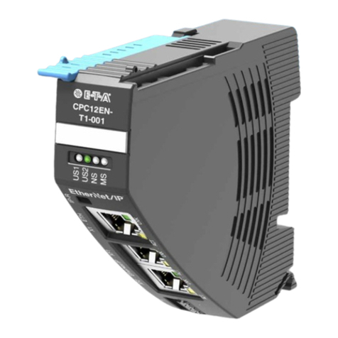
CPC12EN bus controller (ControlPlex®)
2116
7
Description
The customers' demands for a constant quality of the produced
goods while at the same time increasing the quantities, pose great
challenges to the mechanical and plant engineering industry. At
the same time, globalisation is creating worldwide value flows and
production chains. Machines and plants that had still been regionally
organised just a few years ago are now cross-linked worldwide.
These developments extend the requirements of machine and plant
control as well as of the installed components. An ever growing
number of measuring data need to be recorded, analysed, evaluated
and saved. This increases the transparency of the manufacturing
process and thus system availability.
The DC 24 V power distribution is also affected by this development.
The control voltage supplies all essential components of the machine
or system. These include, besides programmable control units,
actuators and sensors. Therefore, the control voltage has a special
importance in the entire production process. Its availability and
stability is crucial for system availability and quality of the produced
goods. The REX system meets these requirements. It consists
of electronic circuit protectors which are connected with each
other via an integral connector sleeve without requiring additional
components. Power supply is via the EM12 supply module which
can supply the circuit protectors with max. 40 A. The new CPC12 bus
controller additionally allows access to all system-relevant data of the
superordinate control systems. This is done via the the EtherNet/IP
interface as well as via an additional Ethernet interface.
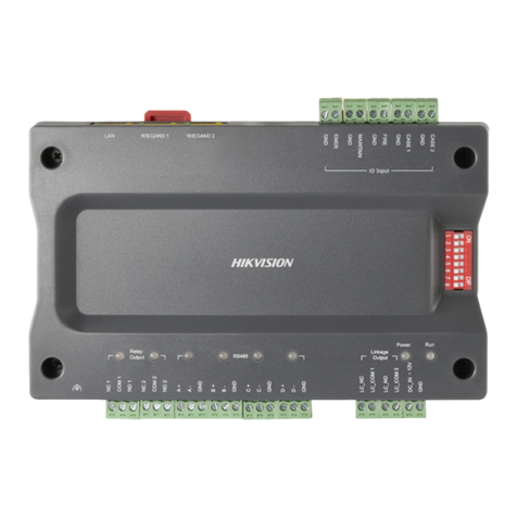
The CPC12 bus controller connects the circuit protectors with the
superordinate control unit. Its internal ELBus®interface realises the
connection with the electronic intelligent circuit protectors of the
REX system. The CPC12 bus controller allows entire access on all
required parameters of the intelligent circuit protectors, their control
unit and the visualisation of the device data.
This is provided at the field bus interfaces for the superordinate
control unit and also at the third RJ45 interface for further connection.
Thus, the system offers a fully parametrisable protection of the DC
24 V circuits and ensures selective overcurrent protection of sensors
and actuators, decentralised peripheral sub-assemblies etc. and their
supply lines.
Features
Your benefits
lControl, diagnosis and monitoring via EtherNet/IP
lFully fledged EtherNet/IP communication interface
lFully fledged Ether communication interface (web server)
lUpdateable via web server
lCombination of supply modules, overcurrent protection and
power distribution
lFor the intelligent circuit protectors of the REX system
lVariable configuration of up to 32 channels with 16 devices
lNo accessories required for connecting the components
lConnection via push-in terminals
lProfitability through extremely reduced wiring time
lReduction of planning, design and installation time
lSimple maintenance, diagnosis and system expansion
lIncreases machine uptime through clear failure detection and
stable power supply
lReduces downtimes through quick error resolution
lSimplifies planning through clear planning sizes
lSaves costs and time through fast and flexible mounting
including integral power distribution solution
CPC12EN
Approvals and certificates Conformity
Approval
authority Standard File certifi-
cate no. Rated voltage
UL UL 2367 E306740 DC 24 V
UL UL 508 Listed
CSA C22.2
No. 14
E492388 DC 24 V
Approvals for EM-accessories: see technical data of accessories.
Downloads
Data sheet/Certificates of conformity/Brochure/CAD data etc. are
available on our web page.
Please observe the separate user manual/installation manual:
CPC12EN-T1
www.e-t-a.de/qr1045/
(With regard to the devices of the REX system...)

www.e-t-a.de
2
CPC12EN bus controller (ControlPlex®)
2116
7
Technical data (Tamb = 25 °C, UB= V)
Visual signalling of RJ45 interfaces
LED LNK
Operating mode Indication of operating mode
Link available green
No link available off
LED ACT
Operating mode Indication of operating mode
Activity available orange blinking
No activity off
General data
Housing material Plastic material
Mounting method Symmetrical rail to EN 60715 - 35 x 7.5
Ambient temperature
(TAMB) -30 °C ...+ 60 °C
(without condensation, cf. EN 60204-1)
Storage temperature -40 °C … +70 °C
Mounting temperature +5 °C … +60 °C
Damp heat 96 hrs / 95% RH RH/40 °C to IEC 60068-
2-78-Cab climate class 3K3 to EN 60721
Altitude 2,000 m above sea level
3,000 m above sea level up to +55 °C
4,000 m above sea level up to +50 °C
Operation pressure 4 bar above atmospheric pressure
Vibration resistance 5 g, test to IEC 60068-2-6 test Fc
Degree of protection IP20
EMC requirements
(EMC Directive, CE
Logo)
Emitted interference: EN 61000-6-3
Noise immunity: EN 61000-6-2
Insulation co-
ordination (IEC 60664)
Overvoltage category II/
pollution degree 3
Instructions for
installation Mounting or actuation of the REX
connector arm must only be effected
at dead-voltage. For start-up the REX
connector arm must be closed.
Technical data (Tamb = 25 °C, UB= V)
Operating voltage UBDC 24 V (18 ... 30 V)
Reverse polarity
protection yes
Quiescent current I0typically 75 mA
Supply via contact lever or additionally
XD1 terminal 0.2 mm2to 1.5 mm2
(push-in) AWG24 – AWG14 str.
Wire stripping length 8 mm
EtherNet/IP interface (XF1, XF2)
RJ45 Connection to Ethernet/IP bus system.
When wiring and connecting to the
Ethernet IP bus system the installation
and wiring regulations of the EtherNet/
IP™ specification have to be observed.
Ethernet interface (X1)
RJ45 Communication interface to web server
IP reset
Momentary switch Reset IP address
(interface X1) by pushing the
momentary switch for min. 3 sec
Dimensions
(H x W x D) 23 x 80 x 98.5 mm
(tolerances to DIN ISO 286 part 1 IT13)
Mass approx. 70 g
System components
EM12-T supply module
Bus controller
Circuit protectors can
be mounted side-by-
side
Types
EM12-T00-000-DC24V-40A
CPC12xx-Tx-xxx
REX12D-T
REX22D-T
Visual operation status indication
by means of multicoloured LED
Operating mode Indication of operating mode
LED US1 LED US2
Supply voltage OK green ---
Firmware update off off
Actuator voltage OK green green
No actuator voltage green red
No device connected
or bus error green orange blinking
Operating mode Indication of operating mode
LED NS (network status)
No IP address off
Valid IP address, no
CIP connection
green blinking
Active CIP connection green
CIP connection time
exceeded
red blinking
Double IP address
detected red
Operating mode Indication of operating mode
LED MS (module status)
Ready to communicate green
Internal configuration green blinking
Critical error recoverable red blinking
Critical error not
recoverable red

www.e-t-a.de
3
CPC12EN bus controller (ControlPlex®)
2116
7
CPC12EN bus controller (ControlPlex®)
Notes
lThe CPC12 bus controller is only intended for use with safety
extra-low voltage (= 24 V DC).
lConnection to a higher or not reliably disconnected voltage can
cause hazardous conditions or damages.
l Only the intended circuit protectors must be used.
l The technical data of the circuit protectors used have to be
observed.
l The entire power distribution system must only be installed by
qualified personnel.
l Only after expert installation must the device be supplied with
power.
l After tripping of the circuit protector and before reset, the cause
of the failure (short circuit or overload) must be remedied.
l The national standards (e.g. for Germany DIN VDE 0100) have
to be observed for installation and selection of feed and return
cables.
lFor convenient adjustment and configuration by means of
projecting software, a master data file (EDS file) will be made
available for downloading on the E-T-A homepage.
lThe CPC12 bus controller is not suitable for controlling safe-
ty-critical or functionally safe applications.
Please observe the separate user instruction manual for the CPC12
bus controller.
Safety Note
Caution:
Electrostatically sensitive sub-assemblies can
be destroyed by voltages far below the human
perception threshold. These voltages already occur
if you touch a component or electrical terminals of a
sub-assembly without being electrostatically discharged. The damage
of a sub-assembly caused by an overvoltage is often not immediately
recognised, but will be noticed only after a longer operating time.
All information and data given on our products are accurate and reliable to the best of our
knowledge, but E-T-A does not accept any responsibility for the use in applications which
are not in accordance with the present specification. E-T-A reserves the right to change
specifications at any time in the interest of improved design and performance. Dimensions
are subject to change without notice. Please enquire for the latest dimensional drawing with
tolerances if required. All dimensions, data, pictures and descriptions are for information
only and are not binding. Amendments, errors and omissions excepted. Part numbers of the
devices may differ from their marking.
EtherNet/IP-communication interface system
Overview of commands:
Writing/reading of device configuration (parameters)
l Current limit value (50 % ... 100 %)
l Rated current (1 A ... 10 A), writing of the rated current is only
possible with device type REX12D-TE and-REX22D-TE.
Reading of static product information
l Product type
l Serial number
l Hardware version
l Software version
Reading of dynamic product information / measuring values
l Status CPC12
l Internal cycle time
l Error memory
l Trip counter
l Reason of last trip
l Device status/ event
l Load voltage: ACTUAL / MIN / MAX / MEDIUM VALUE
l Load current: ACTUAL / MIN / MAX / MEDIUM VALUE
l Supply voltage
l Total current
Control commands
l Switch on/off or reset load output
l Reset trip counter
l Set parameters to factory setting
Ordering information
Series
CPC12 ControlPlex®bus controller
Design: Field bus system
EN EtherNet/IP (connection: 2 x RJ45 female connector)
Mounting method
T Rail mounting
ELBus connections
1 1 connection (right)
product versions
001 Marking
CPC12 EN - T 1 - 001 Ordering example

www.e-t-a.de
4
CPC12EN bus controller (ControlPlex®)
2116
7
Application example: CPC12 sealing
Connector arms can
be locked with
enclosure
Application example: CPC12 distance between
cable duct and connector arm
GERMANY
80 15
60
Mounting position Application example
Terminal selection
GERMANY
X1 – Ethernet interface
XF1 – EtherNet/IP interface
XF2 – EtherNet/IP interface
XD1 + DC24V
XD1 – 0V
XD1 – FE
IP-Reset
LED – LNK
LED – ACT
LED – LNK
LED – ACT
LED – LNK
LED – ACT
XD1 – Supply terminal
LED – US1
LED – US2
LED – NS
LED – MS
Dimensions
CPC12xx-
Tx-xxx
80
23
7.5
98.5
92
Snap-on socket for rail EN 60715-35x7,5
(not included)
Ensure space for plugs and cables!
Label e.g. from
Phoenix Contact
ZBF-21
Connector
arm

www.e-t-a.de
5
CPC12EN bus controller (ControlPlex®)
2116
7
CPC12EN bus controller (ControlPlex®)
Application example
EM12-
T01-001
DC24V
40A
AC
4230-T110
HMI HMI
CPC12EN-
T1-001
US1
US2
NS
MS
EM12-T00
-100-LINE
DC24V
40A
PM12-T01
-00-GND
DC24V
20A
EM12-T00
-000-GND
DC24V
40A
EM12-T00
-300-GND
DC24V
40A
DC24V
REX12D-
TA2-107
DC24V
REX12D-
TA2-107
REX12D-
TA1-107
DC24V
10A 2A
2A 6A
6A
PM12-T01
-00-LOAD
DC24V
20A
M M
4
7
Schaltnetzteil
Power supply
PLC PLC
To next control
cabinet or to
additional supply
To next control
cabinet or to
additional supply

www.e-t-a.de
6
CPC12EN bus controller (ControlPlex®)
2116
7
Application example: CPC12 mounting on or removing from symmetrical rail
Connector arm
can be closed
Push REX
towards rail
Latch on enclosure
downwards
Unlatch with screwdriver,
tilt upwards and remove
(connector arm can be closed)
Mount REX...
side-by-side with EM...
Remove REX... from rail
REX... mount on symmetrical
rail, close connector arm
CPC12 replacement or disassembly
Unlatch with screwdriver
Pull out at right
angles to the rail
Open connector
arm
Open connector
arm
Mounting or actuation of the connector arm must only be effected at
dead-voltage. For start-up, the connector arm must be closed.
Instructions for installation

www.e-t-a.de
7
CPC12EN bus controller (ControlPlex®)
2116
7
CPC12EN bus controller (ControlPlex®)
Accessories: EM12-T00-000-DC24V-40A supply module
98
View X
Contact via connector arm
view X
Entrance Module
EM12-T00-00-DC24V-40A
80
12.4
EM12-
T00-000
DC24V
40 A
OV
OV
LINE +1
LINE +1
GERMANY
LOAD+ 2.1 |(2.2)
LINE+
1
EM12-T
EM12-T00-000-DC24V-40A
EM12-T01-001-DC24V-40A
REX12-T
0 V
LOAD+ 2.1 |(2.2)
LINE+1
EM12-T REX12-T
0 V
13
14
Technical data Schematic diagram
Please observe general data of REX / EM / PM
Operating voltage UBDC 24 V (18 … 30 V)
Operating current IBMax. 40 A
Insulation coordination 0.8 kV / pollution degree 2
Terminals LINE+1
Push-in terminal PT 10
Wire stripping length
0.5 mm2... 10 mm2flexible
AWG24 – AWG8 rigid
18 mm
Terminals 0 V
Push-in terminal PT 2.5
Wire stripping length
0.14 mm2to 2.5 mm2, flexible
0.14 mm2to 4 mm2, rigid
AWG24 – AWG14 str.
8 mm to 10 mm
Dimensions (H x W x D) 12.4 x 80 x 98 mm
Mass approx. 52 g
Approvals UL 2367, File # E306740;
cULus508listed, File # E492388
Other manuals for EtherNetIP ControlPlex CPC12EN
1
This manual suits for next models
1
Table of contents
Other E-T-A Controllers manuals

E-T-A
E-T-A EtherNetIP ControlPlex CPC12EN User manual

E-T-A
E-T-A ControlPlex CPC12 T Series User manual

E-T-A
E-T-A ControlPlex CPC12 T Series User manual

E-T-A
E-T-A EM12D-TMB Series User manual

E-T-A
E-T-A ControlPlex CPC10PB User manual

E-T-A
E-T-A ControlPlex CPC12 User manual

E-T-A
E-T-A ControlPlex CPC12 User manual

E-T-A
E-T-A E-1071-623 User manual

E-T-A
E-T-A Control Plex CPC10PB-T1 User manual

E-T-A
E-T-A ControlPlex CPC20PN User manual