manuals.online logo
Brands
  1. Home
  2. •
  3. Brands
  4. •
  5. Hubbell
  6. •
  7. Controllers
  8. •
  9. Hubbell Load:Logic User manual

Hubbell Load:Logic User manual

PD2794 02/2017 Page 1
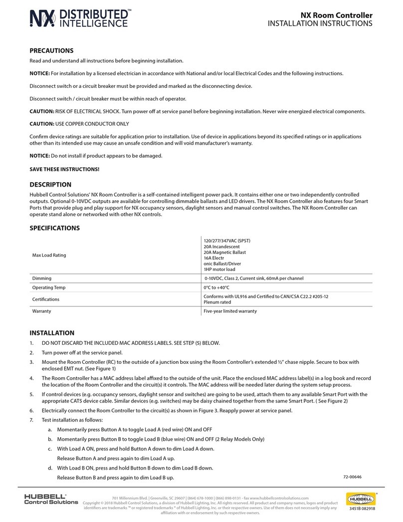
Room Controller
Installation Instructions
Precautions
READ AND FOLLOW ALL SAFETY INSTRUCTIONS.
CAUTION: USE COPPER CONDUCTOR ONLY.
CAUTION - RISK OF ELECTRICAL SHOCK. To prevent electrical shock, turn OFF power at the circuit breaker
before installing or servicing unit. Never wire energized electrical components.
NOTICE: For installation by a licensed electrician in accordance with National and/or local Electrical Codes and the
following instructions.
NOTICE: Do not install if product appears to be damaged.
Be sure to read and understand all instructions before installing or servicing unit
For Indoor use only. Do not use outdoors.
Disconnect switch or a circuit breaker must be provided and marked as the disconnecting device.
The use of accessory equipment not recommended by the manufacturer may cause an unsafe condition.
Confirm device ratings are suitable for application prior to installation. Use of device in applications beyond its specified
ratings or in applications other than its intended use may cause an unsafe condition and will void manufacturer’s
warranty.
All servicing shall be performed by qualified service personnel.
If the equipment is used in a manner not specified by the manufacturer, the protection provided by the equipment
may be impaired.
No user serviceable parts contained inside unit. Refer all service related questions to the factory.
SAVE THESE INSTRUCTIONS!
PD2795 02/2017 Page 1
Room Controller Setup App
Operation Guide
IMPORTANT: This App is designed to assist in the configuration of control parameters for the Hubbell Wiring Device-Kellems
Load:Logic®Room Controller. Once the App has been used to change any setting in a room, manual configuration using the push
buttons and LEDs on the Room Controller will be disabled. All further settings will need to be made using the App. (See Room
Controller Installation Instructions)
START THE APP BY TOUCHING THE NX SCREEN ICON.
When the App starts, you will be prompted to enter a security pin. The default pin is 96@01.
Once started, the App will automatically do a discovery to find all active RCBTM’s (NXBTR)
Bluetooth®interface modules that are in range. After discovery is complete, a list of discovered
RBTM’s will be displayed. Use the signal strength indicators to determine the closest module for
the current room. Modules can also be uniquely identified by the MAC address label on the
module’s housing.
Touch the appropriate module indicator to start a discovery of devices in the room where this
module is installed. Wait for the discovery to complete before making further selections.
When discovery is complete, a listing of the devices found will be displayed. These will include:
1. Room Controllers: Touch to display a list of room controllers found in the room. Touch
one of the room controllers to see a display showing controls for the relay(s) and
dimmer(s), if present, in that room controller. If the room has only one room controller, it
will automatically open when Room Controllers is selected.
The current state of the relays and dimmers will be displayed on the screen. The displays are in
real time.
Use the relay control(s) to change the state of the relay. Use the dimmer control bar to change
the state of the dimmer(s)
Reboot (Top of Screen): Restarts the room controller.
Factory Reset: Sets the room controller and all connected devices back to factory
default settings.
2. Relays: Touch to display a list of relays found in the room. Touch the relay to see a display
of the available relay settings. The current settings will be shown on the display.
Name: Allows the relay to be given a meaningful name. Use the keyboard to enter a
name if desired.
Pri/Sec: Indicates whether this relay is logically a Primary relay or a Secondary relay.
This logic is used with the daylight sensor option to determine the sequence in which
the relay(s) will switch OFF in response to increasing daylight. The Primary relay will
switch first, followed by the Secondary.
Power Up: Select the state this relay will default to upon restoration of power to the
room controller after an outage. The default setting is Last State.
PD2795 02/2017 Page 2
Mode: Indicates how the relay will respond to the occupancy sensor. Occupancy mode is automatic ON. Vacancy mode is
manual ON. This will automatically be set to Vacancy mode for all relays if at least one switch is connected to the room
controller(s).
Occupied: Sets the state of the relay when the room is occupied. Default is ON.
Unoccupied: Sets the state of the relay when the room is unoccupied. Default is OFF.
Groups: A blue background fill in one of the 16 available groups indicates that this relay is selected to be a member of this
group number. A gray background fill indicates that the relay is NOT a member of the group. The relay may be a member
of any or all groups if required.
Relay: Allows manual ON/OFF actuation of the relay in real time.
Make changes as needed. Touch the <Accept> button to save the changes or touch the <Back>
button to exit WITHOUT saving the changes.
3. Dimmers: Touch to display a list of dimmers found in the room. Touch one of the dimmers to
see a display of the dimmer settings:
Name: Allows the dimmer to be given a meaningful name. Use the keyboard to enter a
name if desired.
Power Up: Select the state this dimmer will default to upon restoration after an outage.
<Last State> is the default setting. Touch <Set Level> to enter a specific dim level for
power up. Use the <Level> slider to set the desired level or, touch the box to use the
keyboard to enter the level.
High Trim: Sets the maximum dimming level for this dimmer. The default setting is 100%.
Low Trim: Sets the minimum dimming level for this dimmer. The default setting is 0%
Dim to OFF: If set to <Enabled>, a relay(s) in the same group as the dimmer, will turn
OFF when the dimming level reaches 0%. If set to <Disabled>, a relay(s) in the same
group as the dimmer, will NOT turn OFF when the dimming level reaches 0%.
Mode: Indicates how the dimmer will respond to the occupancy sensor. Vacancy Mode
is Manual ON. Occupancy Mode is Automatic ON.
Occupied Level: Sets the Level of the dimmer when the room is occupied. Default is
Last Level.
Unoccupied Level: Sets the level of the dimmer when the room is unoccupied. Default
is Last Level.
Groups: A blue background fill in one of the 16 available groups indicates that this
dimmer is selected to be a member of this group number. A gray background fill indicates that the dimmer is NOT a
member of the group. The dimmer may be a member of any or all groups if required.
Dimmer: Allows manual actuation of the dimmer in real time.
Make changes as needed. Touch the <Accept> button to save the changes or touch the <Back>
button to exit WITHOUT saving the changes.
PD2795 02/2017 Page 3
4. Switches: Touch to display a list of switches found in the room. Note that each switch display indicates the port number and
switch’s address wheel setting (See RC Switch installation instructions for more details). This is useful for distinguishing
between switches of the same type in the room.
There are a number of different switch types that might be discovered. The setup screens for the various types will differ based on
the function of the switch being selected.
Touch a switch to see the current settings for that switch:
A. Multifunction Switch - # series smart switch:
Name: Allows the switch station to be given a meaningful name. Use the keyboard to
enter a name as desired.
Button: Blue background fill indicates the currently selected button.
Type: Indicates the current button type. The default button type is Toggle. Use the pull
down to display a list of the available button types and select the desired Type from the
list for this button:
Toggle: Touch ON/Touch OFF (default)
ON: Touch for ON only
OFF: Touch for OFF only
Raise: Ramp dimmer up
Lower: Ramp dimmer down
Timed ON: Touch for ON for set time period
Disabled: Button disabled
Groups: A blue background fill in one of the 16 available groups indicates that this switch is selected to be a member of
this group number. A gray background fill indicates that the switch is NOT a member of the group. The switch may be a
member of any or all groups if required.
Make changes as needed. Touch the <Accept> button to save the changes or touch the <Back> button to exit WITHOUT saving
the changes.
B. ON/RAISE/LOWER/OFF (ORLO) and RAISE/LOWER (RL) Switches:
Name: Allows the switch station to be given a meaningful name. Use the keyboard to enter a name as desired.
Raise/Lower Setup: Allows adjustment to the speed at which the dimming level will change as a Raise or Lower button
held down.
Rate: Sets the rate at which level change messages are sent from the switch to the
dimmer. Recommended setting is 300.
% Change: Sets the amount of change that occurs with each message. A setting of 10
will provide about a 5 second transition time from 0% to 100%.
Groups: A blue background fill in one of the 16 available groups indicates that this switch
is selected to be a member of this group number. A gray background fill indicates that the
switch is NOT a member of the group. The switch may be a member of any or all groups
if required.
Make changes as needed. Touch the <Accept> button to save the changes or touch the <Back>
button to exit WITHOUT saving the changes.
PD2795 02/2017 Page 4
C. Scene Switch:
Name: Allows the switch to be given a meaningful name. Use the keyboard to enter a name as desired.
Preset Setup: The buttons are factory configured to control Preset 1 - Preset 4 from top to bottom respectively. Use the
drop down arrow adjacent to a button to choose one of the 16 available presets to be recalled by this button.
Preset Status: Indicates the currently activated preset.
Raise/Lower Setup: Allows adjustment to the speed at which the dimming level will change as a Raise or Lower button
held down.
Rate: Sets the rate at which level change messages are sent from the switch to the dimmer. Recommended setting is
300.
% Change: Sets the amount of change that occurs with each message. A setting of 10 will provide about a 5 second
transition time from 0% to 100% while holding down a Raise or Lower button.
Make changes as needed. Touch the <Accept> button to save the changes or touch the <Back> button to exit WITHOUT saving
the changes.
5. Occupancy Sensors: Note that regardless of the quantity of sensors installed, the App will only indicate a single sensor with a
composite occupancy state for the room.
Name: Allows the sensor to be given a meaningful name. Use the keyboard to enter a name as desired.
Groups: A blue background fill in one of the 16 available groups indicates that this sensor is selected to be a member of
this group number. A gray background fill indicates that the sensor is NOT a member of the group. By default, the
occupancy sensor is set to be a member of all groups.
State: Indicates the Occupied or Unoccupied state of the room as reported by the occupancy sensor at the time the App
screen was accessed. This is read only. Touch the <Refresh> button to re-read the occupancy state of the room.
Make changes as needed. Touch the <Accept> button to save the changes or touch the <Back> button to exit WITHOUT saving
the changes.
6. Daylight Sensor: Touch to display the Photocell set up page. This page allows for the setup of up to 6 zones of daylight
harvesting using a single compatible photocell like the RCDP.
Name: Allows the sensor to be given a meaningful name. Use the keyboard to enter a
name as desired.
Daylight Level: Indicates the current amount of daylight visible to the daylight sensor.
Touch <Refresh> at any time to re -read the daylight level.
Sensor Range: Use the pull down to select the range appropriate to the daylight sensor
model installed. The standard RCDP daylight sensor is factory set to 3 to 300. This is the
nominal default for typical indoor side lighted applications.
Zone #: Use the pull down to select the type of daylight harvesting control to be used for
this zone. The available choices are:
A. None: Daylight harvesting not enabled. This is the default setting for Zones 2-6.
PD2795 02/2017 Page 5
B. ON/OFF Mode: All controlled lighting will turn OFF based on the settings. The controlled lighting will be OFF as long
as there is sufficient daylight to maintain the desired minimum task light level.
Design Level: The target minimum foot candle level at the task work surface.
At Sensor: Indicates the current amount of daylight visible to the daylight sensor. Touch <Get Level> at any time
to refresh the daylight level.
At Task: The amount of light in foot candles as read by a light meter placed at the task surface. Take this reading
with the indoor lighting turned OFF.
Dead Band (%): Provides a band between ON and OFF to prevent unwanted cycling of the load. Typically a
setting of 5% works well.
Make changes as needed. Touch the <Accept> button to save the changes or
touch the <Back> button to exit WITHOUT saving the changes.
C. Step Relay Mode: High, low, OFF switching control based on the
Primary/Secondary setting for the controlled relay(s)
D. Full Dimming Mode: Full range dimming in response to daylight.
Design Level: The target minimum foot candle level to be maintained at the
work surface. Enter the specified foot candle level.
At Sensor: Indicates the current amount of daylight visible to the daylight
sensor. Touch <Get Level> at any time to re read the daylight level.
At Task: The amount of light in foot candles as read by a light meter placed at the task surface. Take this reading
with the electric lighting turned OFF.
NOTE: Make adjustments to the Design Level until the desired foot candle reading is achieved on the light meter
at the task surface.
E. Test Mode: This is the factory default setting for Zone 1. Test mode causes the controlled lighting to react quickly to
bright and dim light such as passing the beam of a flashlight across the daylight sensor.
7. Preset Settings: Touch to display the preset setup page. Use the Preset Select pull down to choose which preset (1 - 16) this
button will affect. Note: the factory default programming, sets Preset 1 to 100%, Preset 2 to 75%, Preset 3 to 50%, and Preset
4 to 25% for all dimmers. NOTE: The “Include” setting determines if this preset will affect the associated dimmer or relay. If the
box is not checked, this preset will NOT change this dimmer or relay when activated.
Fade Time: The fade time for transitions between presets can be set between 1 second and 18 hours. The factory default
fade time is 5 seconds. Use the sliders or type in the box to change the fade time for this preset.
Dimmers: Use the slider or type in the box to set the desired dimmer level for each dimmer.
Relays: Use the controls to set if the relay will be turned ON or OFF when this preset is activated.
After all settings have been selected, touch the <Save> button at the top of the screen. A <Test> button is also provided at the top
of the screen. This button will activate the current preset exactly as if the preset button on the actual switch is touched.
NOTE: Touching the <Test> button immediately after saving a preset will have no affect since the lighting will already be set to the
levels defined for the current preset.
PD2794 02/2017 Page 2
Figure 1
Room Controller mounted
into a 4 x 4 junction box
Figure 2
Room Controller RJ45 ports
to connect control devices
Description
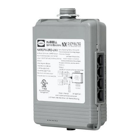
Hubbell Wiring Device-Kellems Load:Logic®Room Controller is a smart device designed to control and manage lighting loads in
a space based on a set of configured parameters. It contains two independently controlled outputs. Optional 0-10VDC outputs
are available for controlling dimmable ballasts and LED drivers. The Load:Logic®Room Controller also features four RJ45 ports
that provide plug and play support for occupancy, daylight sensors and switches for local control. The Load:Logic® Room
Controller can operate in a stand-alone mode or connected with other room controllers.
Installation
1. DO NOT DISCARD THE MAC ADDRESS LABELS INCLUDED WITH THE
PRODUCT. SEE STEP (5) BELOW.
2. The room controller has a MAC address label affixed to the outside of the unit.
Place the enclosed MAC address label(s) in a log book and record the location of
the room controller and the circuit(s) it controls. The MAC address will be needed
later during the system setup process.
3. Turn power OFF at the service panel.
4. Mount the room controller’s enclosure to a ½” knockout opening of an electrical junction box.
Secure it to box tightening the included locknut. (See Figure 1)
5. Connect the control devices (e.g. occupancy sensors, daylight sensor and switches) to
any of the RJ45 ports available using a UTP patch cord. Similar devices (e.g. switches or
occupancy sensors) may be connected together from the same RJ45 port. (See Figure 2)
6. Make the appropriate electrical connections from the room controller to the corresponding
devices as shown in Figure 3.
7. Turn ON the power at the service panel.
8. Test the installation as follows:
a. Momentarily press Button A to toggle Load A (red wire) ON and OFF.
b. Momentarily press Button B to toggle Load B (blue wire) ON and OFF.
c. Turn ON Load A.
d. Press and hold Button A down to decrease the light level on Load A.
e. Release Button A and press again to increase the light level on Load A.
f. Turn OFF Load A.
g. Turn ON Load B
h. Press and hold Button B down to decrease the light level on Load B.
i. Release Button B and press again to increase the light level on Load B.
j. Turn OFF Load B.
PD2794 02/2017 Page 3
Understanding Low Voltage Load Capacity
The room controller is capable of providing a source of 24VDC to power the connected low voltage devices such as switches,
sensors and wireless transmitters. The room controller’s current capacity is 250 mA. Since the control components require
different amounts of current to operate properly, the following table will help to determine how many low voltage devices can be
connected to a single room controller regardless of the RJ45 port in which the device is connected. If two or more room
controllers are connected together, the capacity is determined for each room controller based on the control devices that are
actually connected into that specific room controller. The maximum capacity per room controller is 30 Loads. Below is the
correlation in regards of current requirements per low voltage device.
Switches, Daylight Photocell, and PIR Occupancy Sensor = 1 Load
PIR only Occupancy sensor with RP option = 2 Loads
Dual Technology and Ultrasonic Occupancy sensor = 3 Loads
Dual Technology and Ultrasonic Occupancy sensor with RP option = 4 Loads
NOTE: Only one daylight sensor can be connected in each room/zone
Self-Configuration
The room controller’s sequence of operation will automatically reconfigure as devices are connected as described in the
following sections. Note that self-configuration will automatically be disabled once the room has been manually configured. See
Manual Configuration section.
Occupancy Sensors
The room controller is compatible with any Hubbell Wiring Device-Kellems low voltage occupancy sensor. An RJ45 wiring
adapter (sold separately) is required to make the sensor compatible with the connection to a RJ-45 port in the room controller.
See Figure 3 and HBLRJ45A10 installation instructions. This adapter is color coded to match the flying leads on the sensors.
An occupancy sensor connected to a room controller will be recognized after the first time it cycles occupancy.
When ONLY an occupancy sensor is connected to the room controller, the room controller will set its operation mode to Auto
ON / Auto OFF. Once a smart switch is connected to the room controller, the operation mode will automatically switch to
Manual ON / Auto OFF (vacancy mode). To change one or more load(s) to Auto ON operation see Manual Configuration
section below.
Figure 3
PD2794 02/2017 Page 4
Smart Switches
These devices will automatically configure themselves to control the available loads within 5 seconds after being connected to
the room controller. For best results, do not press any buttons for 5 seconds after connecting a switch to the room controller.
The buttons on the following switch catalog numbers are configured as toggle ON/OFF operation mode by default: RCS1x,
RCS2x, RCS2x, RCS4x, and RCS6x. These switches will self configure to sequentially control the loads. For example, an
RCS1x will control Load A and Load B simultaneously because it only has one button, an RCS2x will control loads A and B,
independently because it has 2 buttons.
The relationship between the buttons and the loads can be configured. See Manual Configuration below. NOTE: If the zone
has more loads than buttons, the last button in the sequence will automatically control the all remaining loads simultaneously.
This insures that no load is left uncontrolled during the self-configuration process.
Switches with specific functions like catalog numbers RCSNFx and RCSTOx, RCSRLx, RCSSCx, RCSNRLFx will self-
configure by default to their respective descriptions. For example; RCSRLx is a Raise/Lower dimmer. Its default operation will
be to change ALL the light levels of connected light fixtures. The relationship between the switch functions and the loads being
controlled can be modified. See Manual Configuration below.
Daylight Sensor
The daylight sensor will self-configure to control Load A when connected to a room controller. The photocell operation can be
verified by observing Load A lighting while alternately covering the photocell (Load A light will be ON and bright if dimming
enabled) or exposing the photocell to bright light (Load A light will be OFF or dimmed if so enabled). The relationship between
the daylight sensor and the load(s) can be changed. See Manual Configuration below.
Figure 4
Manual Configuration
The process of manual configuration allows for the adjustment of certain functions by using the A and B pushbuttons and LED
indicators on the room controller’s enclosure. The functions that can be adjusted are:
1. Assign loads to buttons and switches.
2. Configure loads for Manual ON (vacancy mode) or Auto ON operation mode.
3. Configure loads to respond to the photocell.
4. Calibrate the photocell.
PD2794 02/2017 Page 5
How to Enter Manual Configuration Mode from the Room Controller
To enter manual configuration mode, follow these steps:
1. Simultaneously press and hold the A and B pushbuttons on the room controller until the A and B LED’s start to blink
alternately.
2. Release the A and B pushbuttons. The room controller is now in manual configuration mode. The light fixtures on the
circuit connected to Load A will be ON and all other loads will be OFF.
Note: While in configuration mode no more than one load will ever be ON and the A and B buttons on the room controller will
NOT be able to control the loads.
Hint: If both loads (A and B) are ON or pressing the A or B button switches a load, the room controller is NOT in
configuration mode. Repeat the previous steps to enter manual configuration mode.
Exit Manual Configuration Mode from the Room Controller
To exit manual configuration mode, simultaneously press and immediately release buttons A and B. The room controller will
resume normal operation.
Enter Manual Configuration Mode from a Switch
1. Remove the faceplate from any of the switches in the room and locate the rectangular opening in the plastic bezel
marked “SVC PIN”. Use a small round object such as a straightened paper clip to press the recessed configuration
button for 5 seconds.
2. Observe that the button is located slightly offset from the bezel opening. The LED marked “SVC” will blink while the
configuration button is being pressed.
3. Release the configuration button and note that one load turns ON and all other loads turn OFF indicating that the room
is in manual configuration mode.
Exit Manual Configuration Mode from a Switch
1. Press the configuration button for five seconds. The LED marked “SVC” will blink while the configuration button is
being pressed.
2. Release the configuration button. The loads in the room will restore to the levels they were prior to entering manual
configuration mode.
Assigning a Lighting Load to Buttons in a Switch
As described in the Smart Switches section, all switches assume a default operation of the loads when they are connected to
the room controller’s RJ45 port. The assignment of the loads to the buttons can easily be changed as follows:
Switches with LED indicators:
1. Enter in Manual Configuration Mode from the Switch described above. Load A will be ON. While
load A is ON, each button that controls that load will have a lighted LED.
2. To deny the control function of the load from the button, press the switch button to turn OFF the
button’s LED.
3. To assign control of the load to another button, press the switch’s button to light ON the LED the
button to be paired.
4. Repeat this process for all buttons.
5. To advance to the next load, press and release button A on the room controller. Load A will turn OFF and the next
load will turn ON.
PD2794 02/2017 Page 6
Assign a Load
Deny a Load
6. Repeat the assignment process above for each load.
Switches WITHOUT LED indicators, (RCSOOx, RCSNRLFx, RCSRLx, etc.):
1. Press the ON button or the Raise button to assign control of the load.
2. Press the OFF button or the Lower button to deny control of the load.
3. Tap the recessed configuration button to advance to the next load as necessary.
After all loads are assigned, exit manual configuration mode. Test the button operation and repeat the above if
necessary.
Configure Loads for Auto ON or Manual ON (Vacancy Mode) Operation
1. Enter Manual Configuration Mode from the Room Controller (see section above).
2. While load A is ON, the B LED indicator light on the room controller will identify the current operation mode for the load.
a. If LED B is OFF, the load will operate in manual on (vacancy) mode.
b. If LED B is ON, the load will operate in auto ON mode when the motion sensor detects occupancy.
3. Press and release button B on the room controller to change the operation mode for the current load.
4. To advance to the next load, press and release button A on the room controller.
5. Repeat the above for all loads.
6. When finished, exit manual configuration mode.
Hint: a load set to Manual ON (vacancy) mode must be controlled by an RCSx smart switch, otherwise the load will
never turn ON.
Photocell Configuration Mode
1. Set the room controller to manual configuration mode. See Manual Configuration Mode from the Room Controller
section on page 5.
2. Simultaneously press and hold buttons A and B for three seconds until LED A begins to blink rapidly. This indicates the
room controller has transitioned from load configuration mode into photocell configuration mode.
3. While in photocell configuration mode, only one load will be ON. If the selected load has dimming capability, the light
will cycle between minimum to maximum light levels to identify itself during the selection process.
4. Press and release button B on the room controller. LED B will blink in a pattern to indicate the performance level for
daylight harvesting. The blink patterns are as follows:
a. Double blink/pause indicates normal baseline performance (default setting).
b. Triple blink/pause indicates more aggressive performance, lights will dim more.
c. Single blink/pause indicates less aggressive performance, lights will dim less.
d. No blinking indicates that the selected load will not participate in daylight harvesting.
5. Press and release button B on the room controller to cycle through the performance choices for the selected load. The
“more aggressive” selection will cause the light level to be reduced more during daylight harvesting. The “less
aggressive” selection will cause the light level to be reduced less.
Hint: As a default, if the room controller is equipped with dimming capability (LLC2RD), the photocell will operate in
continuous dimming daylight harvesting mode. If the room controller does not have dimming capability (LLR2R), the
photocell will operate in switching (ON/OFF) daylight harvesting mode based on a default set point of 150 foot-candles.
6. Press and release button A on the room controller save your selection and to advance to the next load.
PD2794 02/2017 Page 7
7. Repeat the above to set the performance for all loads to be controlled by the photocell.
8. Proceed to auto calibration of the photocell.
Hint: The above process can be used to set up multi-zone daylight harvesting in applications where more than one row
of lights are to be controlled. Select a more aggressive performance for the row closest to the windows and a less
aggressive performance for the row away from the windows. As an example, of this process it is possible to set up a
room with three zones of daylight harvesting using the triple blink setting for the row by the window, the double blink
setting for the row in the center, and the single blink setting for the row away from the window.
Auto-Calibrating the Photocell
The photocell must be calibrated before it will perform proper daylight harvesting operation. Be sure to complete the load
assignment process above before proceeding with auto calibration of the photocell.
1. Place the room controller in photocell configuration mode. See Photocell Configuration Mode on page 6.
2. Simultaneously press and hold buttons A and B for three seconds until both LED A and B begin to blink rapidly
indicating the auto calibration process has started.
3. Release buttons A and B. The lights will cycle OFF and ON during the calibration process.
4. When calibration is complete, the room controller will automatically exit configuration mode and return to normal
operation. Daylight harvesting will now be active based on the settings made during configuration.
Reset the Room Controller to Factory Default Settings
To erase all manual configurations and restore the room controller to its factory default settings, perform the following steps:
1. Simultaneously press and hold buttons A and B on the room controller. After a few seconds, LED’s A and B will begin
blink alternately.
2. Continue to hold buttons A and B until the blink pattern changes to a double blink pattern.
3. Release buttons A and B. When the blinking stops, all lighting loads will turn ON indicating the room controller has
been reset to factory default settings.
Hint: If the installation has more than one room controller connected together in the room, the reset process done on
any one of the room controllers will reset ALL of the room controllers.
Reset Factory Defaults Using a Switch
1. Remove the faceplate from any wall switch and locate the rectangular opening in the plastic bezel marked “SVC PIN”.
2. Use a thin object such as a straightened paper clip to press the recessed configuration button for at least 10 seconds.
Observe that the button is located slightly offset from the opening in the bezel.
3. The LED marked “SVC” will blink while the configuration button is being pressed.
4. Release the configuration button and note that all loads in the room turn on indicating that the room has been reset to
factory default settings.

Other Hubbell Controllers manuals

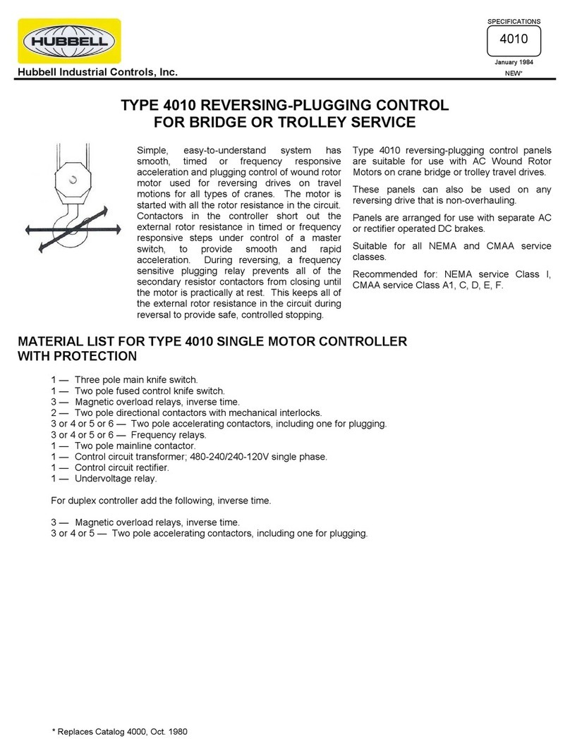
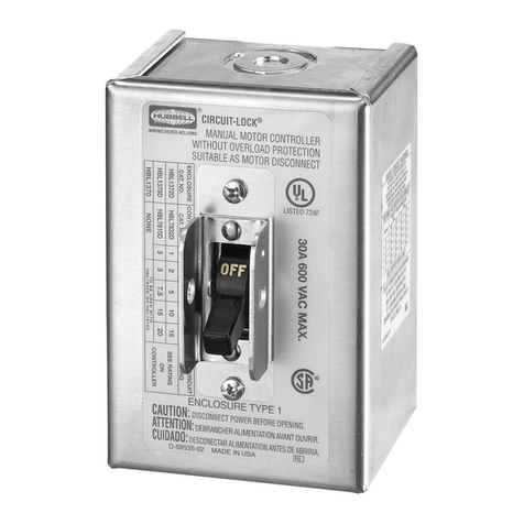
Hubbell Reversing-Plugging Control 4010 User manual

Hubbell

Hubbell Reversing-Plugging Control 4010 User manual

Hubbell T1000 Operating instructions

Hubbell

Hubbell T1000 Operating instructions

Hubbell Fire Pump Controller LX-1500 User manual

Hubbell

Hubbell Fire Pump Controller LX-1500 User manual

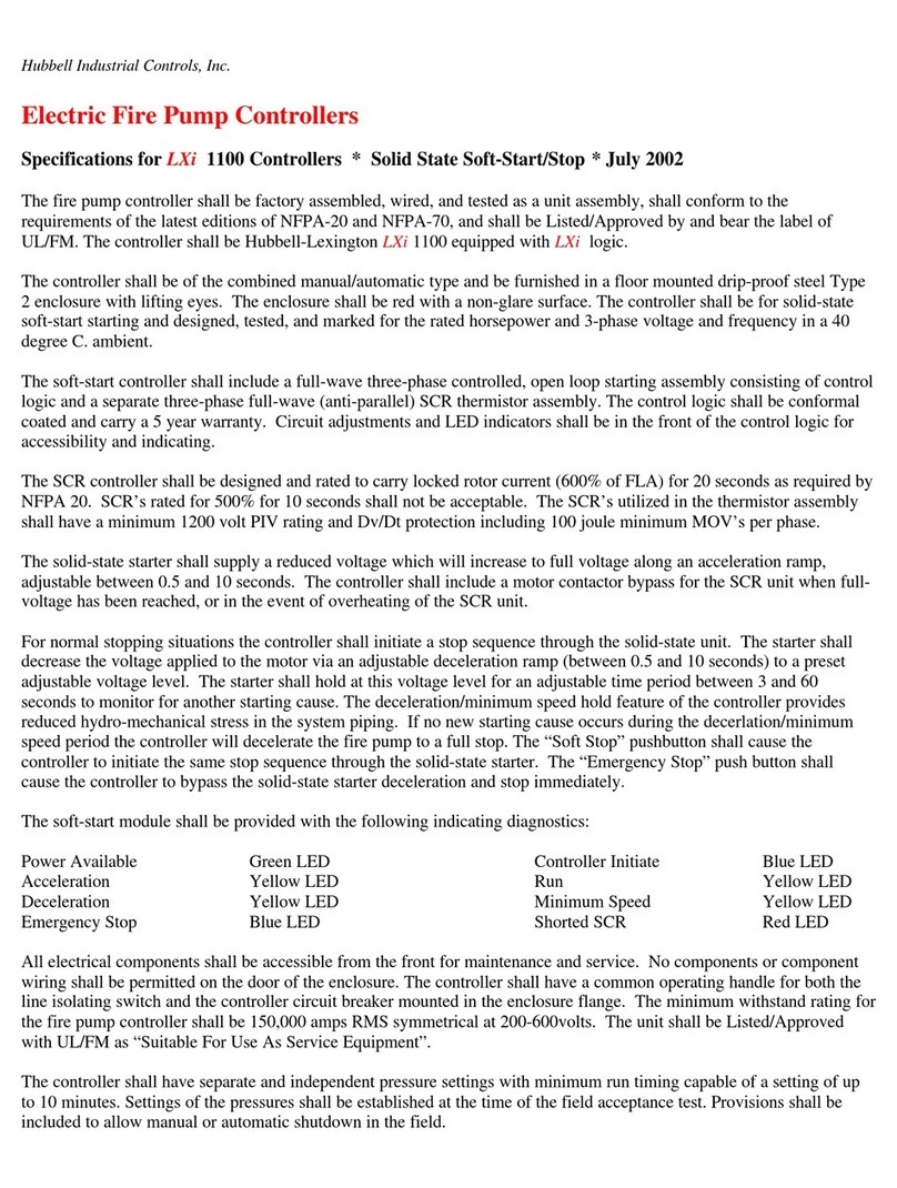
Hubbell Electric Fire Pump Controllers LXi 2900 User manual

Hubbell

Hubbell Electric Fire Pump Controllers LXi 2900 User manual

Hubbell NX Distributed Intelligence NXRCFX Series User manual

Hubbell

Hubbell NX Distributed Intelligence NXRCFX Series User manual

Hubbell GAI-Tronics HUBBCOM GSC3100 User manual

Hubbell

Hubbell GAI-Tronics HUBBCOM GSC3100 User manual

Hubbell Chance CRS User manual

Hubbell

Hubbell Chance CRS User manual

Hubbell Electric Fire Pump Controllers LXi 1300 User manual

Hubbell

Hubbell Electric Fire Pump Controllers LXi 1300 User manual

Hubbell Electric Fire Pump Controllers LXi-1200 User manual

Hubbell

Hubbell Electric Fire Pump Controllers LXi-1200 User manual

Hubbell NX Distributed Intelligence Room Controller User manual

Hubbell

Hubbell NX Distributed Intelligence Room Controller User manual

Hubbell LXi-1100 User manual

Hubbell

Hubbell LXi-1100 User manual

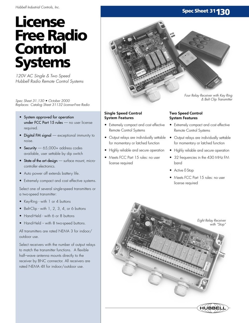
Hubbell 31.130 User manual

Hubbell

Hubbell 31.130 User manual

Hubbell Euclid Lifting Magnet Controller 4296 User manual

Hubbell

Hubbell Euclid Lifting Magnet Controller 4296 User manual

Hubbell GAI-TRONICS E3 User manual

Hubbell

Hubbell GAI-TRONICS E3 User manual

Hubbell Electric Fire Pump Controllers LXi 1900 User manual

Hubbell

Hubbell Electric Fire Pump Controllers LXi 1900 User manual

Hubbell Euclid Lifting Magnet Controller 4295 User manual

Hubbell

Hubbell Euclid Lifting Magnet Controller 4295 User manual

Hubbell Electric Fire Pump Controllers LXi 2100 User manual

Hubbell

Hubbell Electric Fire Pump Controllers LXi 2100 User manual

Hubbell GAI-Tronics HUBBCOM GSC1100 User manual

Hubbell

Hubbell GAI-Tronics HUBBCOM GSC1100 User manual

Hubbell Electric Fire Pump Controllers LXi 2200 User manual

Hubbell

Hubbell Electric Fire Pump Controllers LXi 2200 User manual

Hubbell Electric Fire Pump Controllers LXi 1400 User manual

Hubbell

Hubbell Electric Fire Pump Controllers LXi 1400 User manual

Hubbell Electric Fire Pump Controllers LXi 1700 User manual

Hubbell

Hubbell Electric Fire Pump Controllers LXi 1700 User manual

Hubbell Electric Fire Pump Controllers LXi-2700 User manual

Hubbell

Hubbell Electric Fire Pump Controllers LXi-2700 User manual

Hubbell HBL1372D User manual

Hubbell

Hubbell HBL1372D User manual

Hubbell Euclid Lifting Magnet Controller 4291 User manual

Hubbell

Hubbell Euclid Lifting Magnet Controller 4291 User manual

Popular Controllers manuals by other brands

esera ECO 503 quick guide

esera

esera ECO 503 quick guide

Carel uAM user manual

Carel

Carel uAM user manual

ABB ABB-Welcome manual

ABB

ABB ABB-Welcome manual

LAE electronic AC1-5A series Instructions for use

LAE electronic

LAE electronic AC1-5A series Instructions for use

Resol DeltaTherm HC MAX Manual for the specialised craftsman

Resol

Resol DeltaTherm HC MAX Manual for the specialised craftsman

Danfoss DMS 300 operating instructions

Danfoss

Danfoss DMS 300 operating instructions

Supmeter BST100-B11 Operation manual

Supmeter

Supmeter BST100-B11 Operation manual

LS XGT Series manual

LS

LS XGT Series manual

Teracom TCW112-WD user manual

Teracom

Teracom TCW112-WD user manual

Siemens 3RA2220 Original operating instructions

Siemens

Siemens 3RA2220 Original operating instructions

KMC Controls CSC-2000 Series installation guide

KMC Controls

KMC Controls CSC-2000 Series installation guide

Spirax Sarco LC1350 Installation and maintenance instructions

Spirax Sarco

Spirax Sarco LC1350 Installation and maintenance instructions

Hansen FROST MASTER Installation

Hansen

Hansen FROST MASTER Installation

Rosemount 3095 product manual

Rosemount

Rosemount 3095 product manual

Eaton CEAG CG-Controller operating instructions

Eaton

Eaton CEAG CG-Controller operating instructions

ATI Technologies 9150-PCFC-12 product manual

ATI Technologies

ATI Technologies 9150-PCFC-12 product manual

Regin RVAZ2-24A Instruction

Regin

Regin RVAZ2-24A Instruction

ivact iVQ-E manual

ivact

ivact iVQ-E manual

manuals.online logo
manuals.online logoBrands
  • About & Mission
  • Contact us
  • Privacy Policy
  • Terms and Conditions

Copyright 2025 Manuals.Online. All Rights Reserved.