manuals.online logo
Brands
  1. Home
  2. •
  3. Brands
  4. •
  5. ComAp
  6. •
  7. Controllers
  8. •
  9. ComAp InteliNano NT MRS User manual

ComAp InteliNano NT MRS User manual

ComAp,a.s.
Kundratka 2359/17
180 00, Praha 8
Czech Republic
InteliNano-NT MRS, SW version 1.5, ©ComAp –September 2013 1
InteliNano-NT-MRS-1.5-Fast User Guide.pdf
CAN INTERFACE
GENERATOR VOLTAGE
MEASUREMENT
T16 = Neutral
T17 = Phase 1
T18 = Phase 2
T19 = Phase 3
USB interface
L
COM
H
INTPUT TERMINALS
T10 = COM for analog inputs
T11 = binary input
T12 = binary input
T13 = binary/analog input –Low Fuel Level
T14 = binary/analog input –Coolan Temperature
T15 = binary/analog input –Oil Pressure
OUTPUT TERMINALS
T04 = binary output –Starter (6A)
T05 = binary output - Fuel Solenoid (6A)
T06 = binary output (500 mA)
T07 = binary input/output (500 mA)
POWER SUPPLY, D+
T01 = BATT -
T02 = D+
T03 = BATT +
G
ECU
DIESEL / GASOLINE ENGINE GENERATOR
LOAD
Fuel Solenoid
Battery
Sarter
Fuel Level Analog
Coolant Temperature Analog
Oil Pressure Analog
D+
-+
Alarm
Ready To Load
Fuel Solenoid
Starter
COM
Remote Start And Load
Emergency Stop
CAN
L COM H
USB
Battery +
Battery -
D +
PC
L1
L2
L3
N
InteliNano NT

MRS Fast User Guide
Typical wiring diagram
Accessing the setup mode
Ensure the engine is stopped and the controller is in Manual mode (green LED above button Auto is turned off).
If you have not configured the custom initialization (init) screen then press and hold Stop button, then briefly press ▲button and then Auto .
If you have already created your own init screen then press and hold Stop button and then briefly press ▲, the custom init screen will appear, keep holding the Stop
button. Then press ▼to switch LCD to default init screen, and then press Auto.
To move up and down in the setup menu use ▲and ▼buttons. Press Start button to select or Stop button for exit.
Basic settings
Input settings
Engine parameters and protections
ECU setting
Generator protections
Info
Output settings
Outputs and inputs
Output
code
Output source
Type
Terminal assignment
O00
Not Used
binary
T04, T05, T06, T07
O01
Starter
binary
T04
O02
Fuel Solenoid
binary
T04, T05, T06, T07
O03
Stop Solenoid
binary
T04, T05, T06, T07
O04
Alarm
binary
T04, T05, T06, T07
O07
Ready To Load
binary
T04, T05, T06, T07
O08
Prestart
binary
T04, T05, T06, T07
O09
ECU Power Relay
binary
T04, T05, T06, T07
O10
Choke
binary
T04, T05, T06, T07
O11
Glow Plugs
binary
T04, T05, T06, T07
Normally Open Contact –output
Normally Open Contact - input
button
Normally Closed Contact –output
Normally Closed Contact –input
button
User curves
I21
I23
I25
VDO Level %
VDO 5 Bar
VDO 40-120 °C
Datcon Level %
VDO 10 Bar
VDO 50-150 °C
Datcon 5 Bar
Datcon High °C
Datcon 7 Bar
Datcon Low °C
Datcon 10 Bar
Not selected
Not selected
Not selected
Input
code
Input source
Type
Terminal assignment
I00
Not Used
binary
T07, T11, T12, T13, T14, T15
I01
Emergency Stop
binary
T07, T11, T12, T13, T14, T15
I02
Remote Start/Stop
binary
T11
I03
Remote Start And Load
binary
T11
I04
Access Lock
binary
T07, T11, T12, T13, T14, T15
I07
GCB Feedback
binary
T07, T11, T12, T13, T14, T15
I10
External Warning 1
binary
T07, T11, T12, T13, T14, T15
I11
External Warning 2
binary
T07, T11, T12, T13, T14, T15
I12
External Warning 3
binary
T07, T11, T12, T13, T14, T15
I13
External Shutdown 1
binary
T07, T11, T12, T13,T14, T15
I14
External Shutdown 2
binary
T07, T11, T12, T13, T14, T15
I15
External Shutdown 3
binary
T07, T11, T12, T13, T14, T15
I20
Low Fuel Level
binary
T07, T11, T12, T13, T14, T15
I21
Fuel Level Analog
analog
T13, T14, T15
I22
Low Oil Pressure
binary
T07, T11, T12, T13, T14, T15
I23
Oil Pressure Analog
analog
T13, T14, T15
I24
High Coolant Temperature
binary
T07, T11, T12, T13, T14, T15
I25
Coolant Temperature Analog
analog
T13, T14, T15
I29
Fuel Level SD
Binary
T07, T11, T12, T13, T14, T15
Dimensions
Case dimensions: 118mm x108mm x 40mm
Panel Cutout: 96mm x 96mm
WARNING!
If D+ is not used, connect this terminal to battery positive!
ComAp,a.s.
Kundratka 2359/17
180 00, Praha 8
Czech Republic
InteliNano-NT MRS, SW version 1.5, ©ComAp –September 2013 2
InteliNano-NT-MRS-1.5-Fast User Guide.pdf
Setpoints
Use ▲and ▼buttons to move or change value. Start button to select setpoint or confirm changes and Stop button to go back.
Basic settings
Setpoint
code
Setpoint name
B01
Nominal Voltage Ph-N
80 –480 V
B02
Nominal Voltage Ph-Ph
80 –600 V
B03
Nominal Frequency
50 Hz (1), 60 Hz (2)
B04
Connection Type
Mono Phase (1), SplitPhase (2),
3Ph3Wire (3), 3Ph4Wire (4)
B05
Units Format
Metric unit format (1), US unit
format (2)
B07
Zero Power Mode Delay
0-360 min
B08
Light Tower Mode
Disable (1), Enable (2)
B09
Nominal RPM
100-4000
Engine parameters and protections
Setpoint
code
Setpoint name
E01
Prestart Time
0-600 s
E02
Maximum Cranking Time
0-60 s
E03
Cooling Time
0-3600 s
E04
Oil Pressure Shutdown
0-10 Bar
E05
Coolant Temperature Shutdown
0 -150 °C
E15
Fuel Level Shutdown
0 –20%
E06
Battery Undervoltage
8 –40 V
E07
Warning Maintenance
0 –10000 h
E08
Oil Pressure Starter Disengagement
Disable (1), Enable (2)
E09
Choke Time
0 –3600 s
E10
Minimal Stabilization Time
1 –300 s
Generator protections
Setpoint
code
Setpoint name
G01
Generator Overvoltage Shutdown
G02 –200 %
G02
Generator Undervoltage Shutdown
0 - G01 %
G03
Generator Overfrequency Shutdown
G04 –130 %
G04
Generator Underfrequency Shutdown
0 –G03 %
To apply all changes return to the main setup menu and restart the controller by pressing the Stop button.
Alarms and Events
Events
Manual Start
Remote Start
Manual Stop
Remote Stop
Auto On
Auto Off
Power On
Island Operation
Warnings
Warning Maintenance
Low Battery
Low Fuel Level
External Warning 1
External Warning 2
External Warning 3
ECU Communication Error
Shutdowns
Emergency Stop
Overspeed
Underspeed
Low Oil Pressure
High Coolant temperature
External Shutdown 1
External Shutdown 2
External Shutdown 3
GCB Fail
Generator Overvoltage
Generator Undervoltage
Generator Overfrequency
Generator Underfrequency
Generator CCW Rotation
Start Fail
Stop Fail
Battery Flat
Fuel Level SD
ECU
For ECU configuration use PC software NanoEdit. For more details see InteliNano AMF Reference Guide.
Technical data
Power supply range
6-36 VDC
Power supply drop-out immunity
100 ms
Power consumption
35 –295 mA
Zero Power Mode consumption
52 - 344 µA
Operating temperature
-20... 70 °C
Operating humidity
95% non-condensing (IEC/EN 60068-2-30)
Protection degree (front panel)
IP65 with GASKET 4x405 only
IP50 without gasket
Storage temperature
-30... 80 °C
Binary outputs (up to 4)
Low current outputs (2)
500 mA
High current output (2)
6 A (long term) / 10 A (short term)
Total output current
10 A (long term) / 16 A (short term)
Binary inputs (up to 6)
Input resistance
1,5 kΏ
Closed contact voltage
<2 V
Open contact voltage
>3,5 V
Analog inputs (up to 3)
Galvanic insulation
Not insulated
Electrical range
0 - 2500 kΏ
Resolution
0,1 Ώ
Precision
2 % ± 3 Ώ
Charging alternator preexcitation circuit
Excitation current
100 mA
Charging fail threshold
80 %
Generator/Mains measurements
Measurement input
3ph generator voltage
Measurement type
True RMS
Voltage range
480 V Ph-Ph (277 V Ph-N)
Max. measured voltage
340 V Ph-N
Voltage accuracy
1%
Frequency range
40 –70 Hz
Frequency accuracy
1 %

Other manuals for InteliNano NT MRS

1

Other ComAp Controllers manuals

ComAp InteliCompact NT Manual

ComAp

ComAp InteliCompact NT Manual

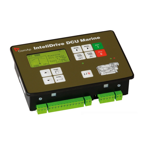
ComAp InteliDrive DCU Marine User manual

ComAp

ComAp InteliDrive DCU Marine User manual

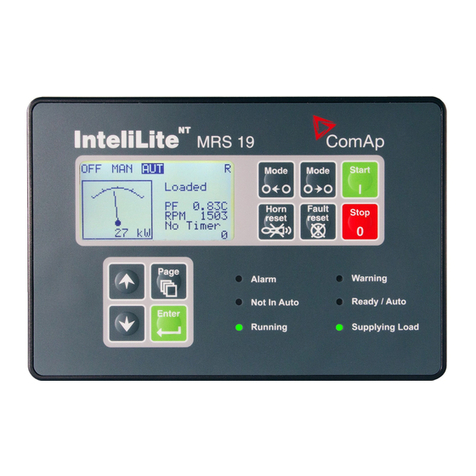
ComAp InteliLite MRS16 User manual

ComAp

ComAp InteliLite MRS16 User manual

ComAp IG-NT User manual

ComAp

ComAp IG-NT User manual

ComAp ECON-4 Instruction manual

ComAp

ComAp ECON-4 Instruction manual

ComAp InteliATS NT PWR User manual

ComAp

ComAp InteliATS NT PWR User manual

ComAp InteliDrive DCU Industrial User manual

ComAp

ComAp InteliDrive DCU Industrial User manual

ComAp InteliMains 210 BTB User manual

ComAp

ComAp InteliMains 210 BTB User manual

ComAp IG-NT User manual

ComAp

ComAp IG-NT User manual

ComAp InteliATS NT STD User manual

ComAp

ComAp InteliATS NT STD User manual

ComAp IG-NT GC User manual

ComAp

ComAp IG-NT GC User manual

ComAp InteliLite 4 MRS16 Manual

ComAp

ComAp InteliLite 4 MRS16 Manual

ComAp InteliSys SPI Use and maintenance manual

ComAp

ComAp InteliSys SPI Use and maintenance manual

ComAp InteliLite 4 AMF 20 User manual

ComAp

ComAp InteliLite 4 AMF 20 User manual

ComAp InteliDrive Mobile User manual

ComAp

ComAp InteliDrive Mobile User manual

ComAp IGS-NT Series User manual

ComAp

ComAp IGS-NT Series User manual

ComAp IG-NT GC User manual

ComAp

ComAp IG-NT GC User manual

ComAp IG-NT GC User manual

ComAp

ComAp IG-NT GC User manual

ComAp InteliDrive FLX LITE User manual

ComAp

ComAp InteliDrive FLX LITE User manual

ComAp IG-NT User manual

ComAp

ComAp IG-NT User manual

ComAp InteliNano NT Plus User manual

ComAp

ComAp InteliNano NT Plus User manual

ComAp L151006001 User manual

ComAp

ComAp L151006001 User manual

ComAp IM-NT-BB User manual

ComAp

ComAp IM-NT-BB User manual

ComAp InteliNano NT Plus User manual

ComAp

ComAp InteliNano NT Plus User manual

Popular Controllers manuals by other brands

Samson Type 5824 Mounting and operating instructions

Samson

Samson Type 5824 Mounting and operating instructions

Tiltamax Nucleus Nano WLC-T04 user guide

Tiltamax

Tiltamax Nucleus Nano WLC-T04 user guide

Allen-Bradley 20F installation instructions

Allen-Bradley

Allen-Bradley 20F installation instructions

Timpex ECO 100+ user manual

Timpex

Timpex ECO 100+ user manual

RIFT Actuators RIFT 200 Installation, operation & maintenance instructions

RIFT Actuators

RIFT Actuators RIFT 200 Installation, operation & maintenance instructions

Forch 5439 1700 manual

Forch

Forch 5439 1700 manual

futuredesion LIMIT L41 user manual

futuredesion

futuredesion LIMIT L41 user manual

Omron SYSMAC CPM2A Operation manual

Omron

Omron SYSMAC CPM2A Operation manual

Siemens REA23M Operating	 instruction

Siemens

Siemens REA23M Operating instruction

Linak HB100 quick guide

Linak

Linak HB100 quick guide

Chemtrol 255 instruction manual

Chemtrol

Chemtrol 255 instruction manual

Emerson Fisher 67C instruction manual

Emerson

Emerson Fisher 67C instruction manual

Beka LED BKL-DMXRGBW user manual

Beka LED

Beka LED BKL-DMXRGBW user manual

Munters Green Field installation manual

Munters

Munters Green Field installation manual

MoistMaster E35 BT Quick start guides

MoistMaster

MoistMaster E35 BT Quick start guides

SDC 101-DE installation instructions

SDC

SDC 101-DE installation instructions

YASKAWA J1000 CIMR-JC series quick start guide

YASKAWA

YASKAWA J1000 CIMR-JC series quick start guide

YOKOGAWA UTAdvanced UT32A technical information

YOKOGAWA

YOKOGAWA UTAdvanced UT32A technical information

manuals.online logo
manuals.online logoBrands
  • About & Mission
  • Contact us
  • Privacy Policy
  • Terms and Conditions

Copyright 2025 Manuals.Online. All Rights Reserved.