Pub. 42004-141C
Model 703-002 and 7335-002 Multi-Party 24 V DC Amplifier Enclosures Page: 2of 9
f:\standard ioms - drafts\instr. manuals (42004)\42004-141c\42004-141c.doc
01/03
In 24-volt systems, plan on several branch lines from the dc source with no more than six stations per
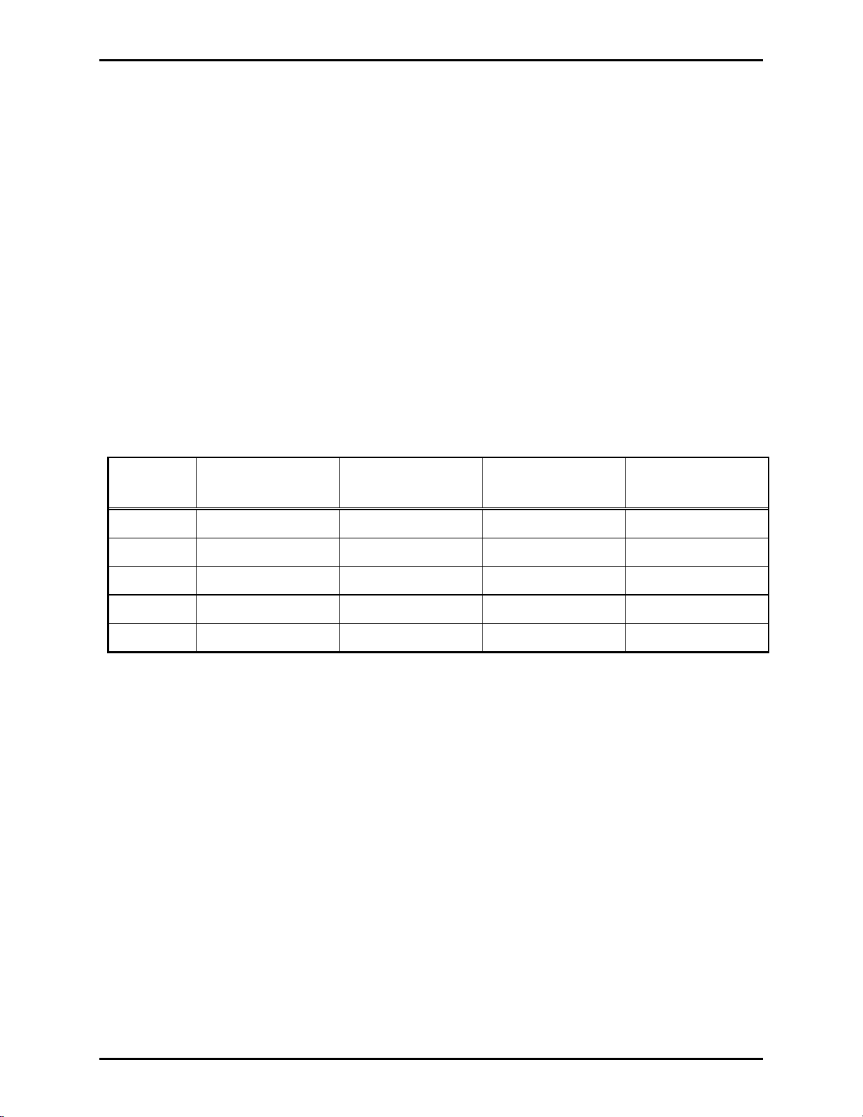
branch. One branch could span up to 4,000 feet for a single station. The Maximum Cable Distance Table
lists the limits. Where two or more stations are listed, the assumption is that they are evenly spaced along
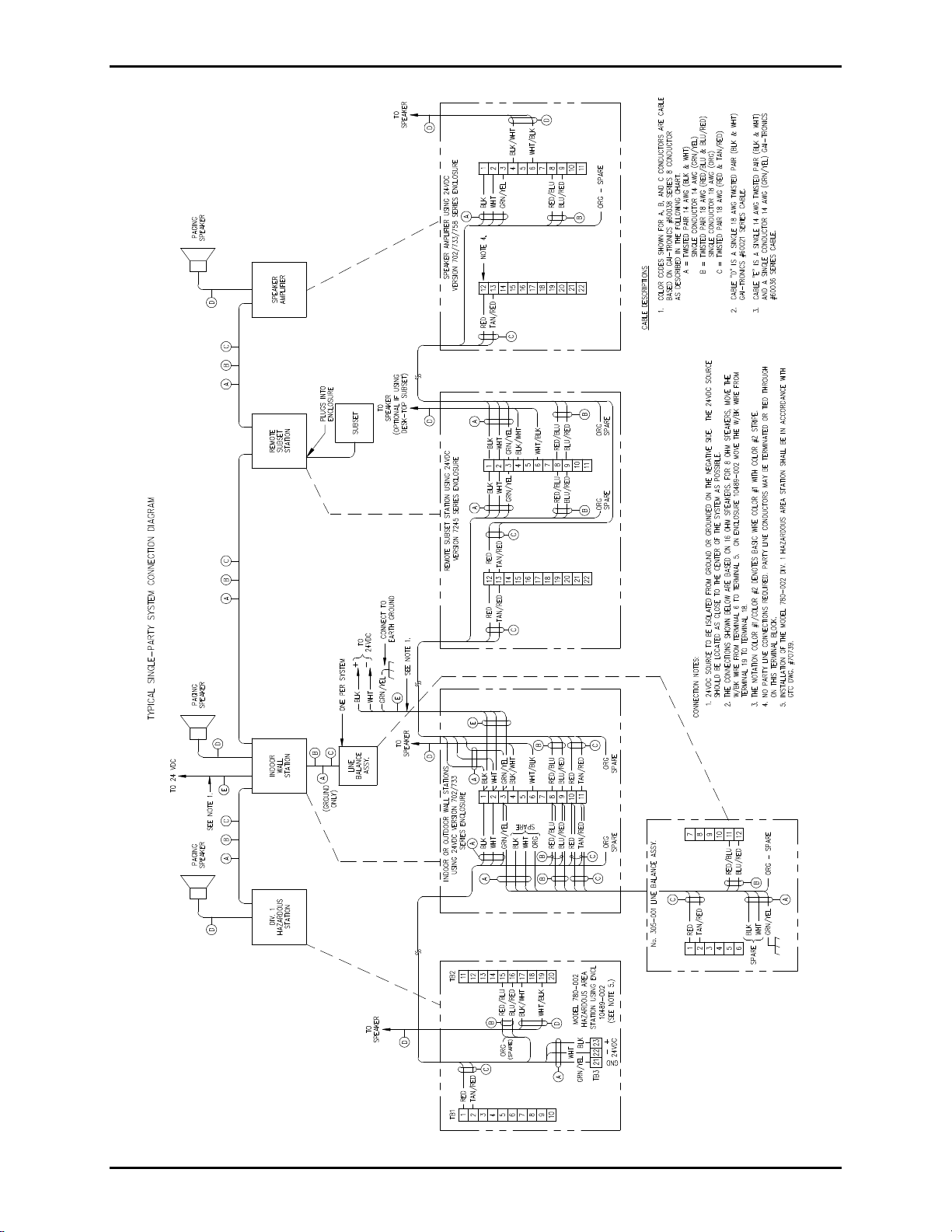
the cable. The figures at the end of this manual show the 24 V dc system layout and provide guidance in
placing add-on stations.
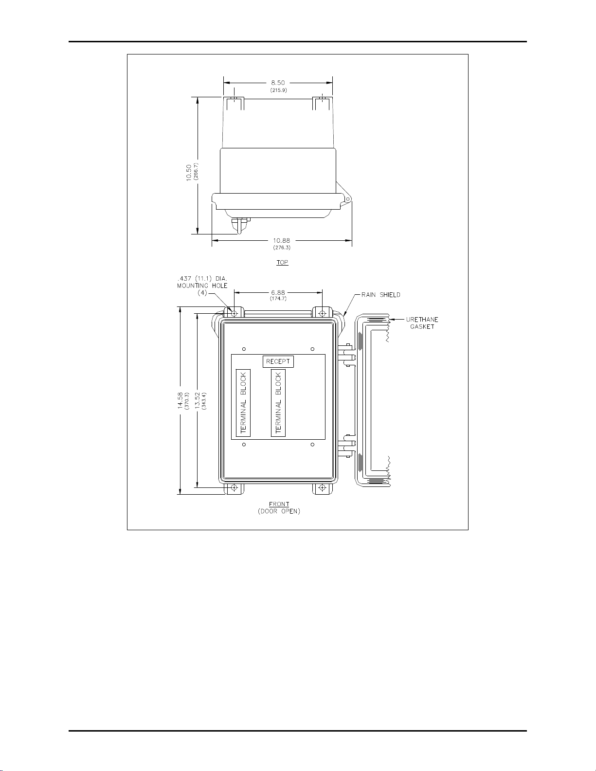
Enclosure Placement
All GAI-Tronics Page/Party®units are wired in parallel. Good system layout design minimizes the cable
required for each installation. GAI-Tronics multi-conductor cable, designed especially for this application,
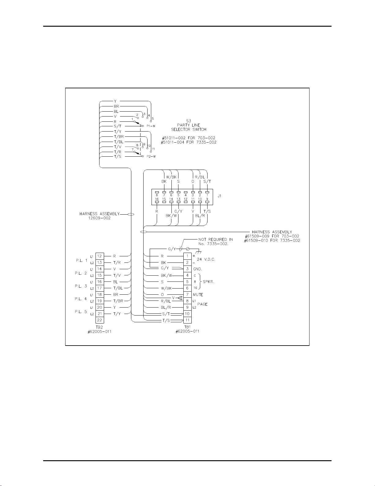
is recommended. The number, size, and color-coding of conductors are listed in the accompanying system
connection diagrams.
When installing Page/Party®equipment, the system layout and power cable length are important
considerations. Consult the Maximum Cable Distance table for typical cable lengths. The cable distance
between stations as well as total cable distance must be considered. Cable distance is more strictly
regulated in 24 V dc systems because of the amount of resistance these cables encounter—the longer the
cable distance, the greater the resistance and IR losses (voltage drop) encountered.
Maximum Cable Distance in Feet*
Number
of Units 14 AWG
Total/Between 12 AWG
Total/Between 10 AWG
Total/Between 8 AWG
Total/Between
14,000/4,000 6,400/6,400 10,000/10,000 16,000/16,000
22,800/1,400 4,480/2,240 7,000/3,500 11,200/5,600
32,000/660 3,200/1,060 5,000/1,667 8,000/2,667
61,200/200 1,920/320 3,000/500 4,800/800
9800/90 1,280/142 2,000/222 3,200/356
*based on GTC-supplied cable.
The Maximum Cable Distance table is based on speech signals. With continuous tone signals, each station
will be driven to 12 watts and the distances should be reduced by half, or ideally to a fourth, to minimize
distortion. The current drain is 1.1 amps when the amplifier is producing a 12-watt sine wave output.
Speech signals do not have the energy content of a continuous tone, and therefore, do not require as much
average current.
Each amplifier contains two fuses on the PCBA in the 24 V dc input to protect and isolate the handset and
speaker amplifier circuitry in the event of a failure. Power line wiring to each amplifier or group of
amplifiers should have a fuse or circuit-breaker to protect against wiring failures. If cable with 14 AWG
power line conductors is used, a 15-amp fuse or circuit breaker should be installed for each branch line at
the point it connects to the battery. Fuse or circuit breaker rating is determined by the size cable used in the
branch. Consult the National Electrical Code (NFPA70) or Canadian Standards Association (CSA 22.1)
for the maximum allowable capacity of the wire used.


 user manual")