Installation Instructions Directives de montage Instrucciones de instalación
PD2217
Wiring Device-Kellems
Hubbell Incorporated (Delaware)
185 Plains Road
Milford, CT 06461-2420
(203) 882-4800
English Français Español
(Page 1) 05/08 PRINTED IN U.S.A.
GENERAL INFORMATION
CAUTION: Nonmetallic flange/cover are not intended to be used in high traffic
installations and are not intended to support furniture.
CAUTION:RISKOFELECTRICALSHOCK.Disconnectpowerbeforeinstalling.
Never wire energized electrical components.
NOTICE: For Installation by a qualified electrician in accordance with national
and/or local electrical codes.
NOTICE:INSUREDATA/COMMUNICATIONSARESEPARATEDFROMPOWER
APPLICATIONS.
NOTICE: Check that the device’s type and rating are suitable for the application.
Install devices to manufacturers instructions.
INSTALLATION INSTRUCTION
1. PriortoinstallingtheRaisedAccessFloorBox(A),an9”x7”[229mmx178mm]
(+1/16”–0”)openingmustbecutinraisedfloorpanel.Theoveralldepthofbox
is 5.22” [133mm].
2. The Raised Access Floor Box will accept up to four power devices (B) or a
combinationofpowerandlowvoltagedevicesinitsfourcompartmentsprovided.
For use with NEMA5-15R and 5-20R Single, Duplex or Style Line (Standard
and Isolated Ground) devices.
3. Field Wired Boxes – Cat No. HBLAFB101GNT, HBLAFB101BK
Thepowercompartmentsoftheseboxesaretobefieldwired.UseonlyULListed
receptacles. Remove the appropriate knockout (C) from the back bracket (D)
andattachtheconduit connector.Wiredevicesin accordance withthenational
andlocalelectricalcodesandattachthebackbracket(D)tothebox(A).Mount
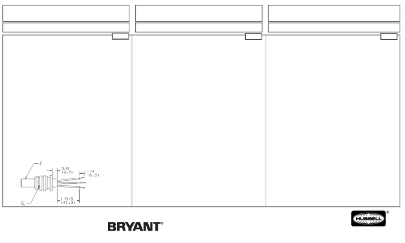
devices (B) to the die cast device mounting bracket (F) and install device face
plates (E).
4. Thediecastdevicemountingbracket(F)canbeseparatedfrombox(A)toallow
faceplates (E) to be easily installed.
5. Prewired Boxes
a) Determine the correct orientation of theAFB, and insert theAFB into the
access floor.
b) TemporarilyremovingtheAFB from the access floor,androtating the two
Jack Screws (G), may accomplish additional adjustments for extremely
thick or thin floor tiles.
6. After ensuring that theAFB is correctly located and adjusted:
a) Temporarily remove the AFB from the access floor, and fully make the
ExtenderCableconnection(ifequippedwithamulti-polemodularconnector)
in accordance with Connection Installation Instructions, PD2188.
b) IftheAFBisprovidedwithstrippedwireleadsontheExtenderCable,wire
into the intended location per national and local electrical codes.
7. Apply a ¼ inch (6.3 mm) thick continuous bead of electrical grade type RTV
silicone compound completely around the perimeter on the underside of the
Trim Ring.
RENSEIGNEMENTSGÉNÉRAUX
ATTENTION-Lesrebordsetlescouverclesnonmétalliquesnesontpasprévuspour
les endroits à circulation intense ni pour supporter des meubles.
ATTENTION - RISQUE DE CHOC ÉLECTRIQUE. Débrancher le circuit avant
de procéder au montage. Ne jamais câbler des composants électriques dans un
circuit sous tension.
AVIS - Doit être installé par un électricien qualifié selon les codes en vigueur.
AVIS - S’ASSURERQUELESCIRCUITSDEDONNÉESETDECOMMUNICATIONS
SONT SÉPARÉS DES CIRCUITS D’ALIMENTATION ÉLECTRIQUE.
AVIS - S’assurer que le type et les caractéristiques nominales de ce dispositif
conviennent à l’application. Installer les dispositifs selon les directives du
fabricant.
MONTAGE
1. Avant d’installer la boîte de faux-plancher (A), une ouverture de 22,9 cm x 17,8 cm
(+1,5 mm - 0) doit être pratiquée dans le panneau du faux-plancher. La profondeur
horstoutdela boîte estde13,3cm.
2. La boîte de faux-plancher peut accommoder jusqu’à quatre dispositifs d’énergie (B)
ou unecombinaison dedispositifs d’alimentationetde basse tensiondans lesquatre
compartiments fournis. Convient aux dispositifs NEMA5-15R et 5-20R simples,
doubles ou Style Line (MALT standard et isolée).
3. Boîtes câblées sur le terrain –Nºde réf.HBLAFB101GNT,HBLAFB101BK.
Lescompartimentsd’alimentationdoiventêtrecâbléssurleterrain.Utiliseruniquement
despriseshomologuéesUL/CSA.Enleverlesdébouchuresappropriées(C)delaparoi
arrièredelaboîte(D)etfixerlesraccordsdeconduit.Câblerlesdispositifsselonlescodes
d’électricitéenvigueuretfixerlaparoiarrière(D)àlaboîte(A).Monterlesdispositifs(B)
àl’accessoirede fixation moulédesdispositifs(F)et installerlesplaques(E).
4. L’accessoiredefixationmoulédesdispositifs(F)peutêtreséparédelaboîte(A)pour
permettred’installerfacilementles plaques (E).
5. Boîtes précâblées
a) Déterminer l’orientation appropriée de la boîte puis l’insérer dans le faux-
plancher.
b) Retirer temporairement la boîte du faux-plancher et tourner les deux vis de
levage(G)pourunajustementcomplémentairedanslecasd’unrevêtement
de sol extrêmement épais ou mince.
6. Une fois la boîte correctement positionnée et ajustée :
a) Retirer temporairement la boîte du faux-plancher et effectuer la connexion
du câble de prolongation (si doté d’un connecteur modulaire multipolaire)
conformément aux directives du PD2188.
b) Lorsque la boîte comprend des fils dénudés à l’extrémité du câble de
prolongation, les raccorder aux endroits appropriés selon les codes
d’électricité nationaux et locaux.
7. Appliquer un cordon continu de 6 mm de pâte à calfeutrer à la silicone de type
RTV pour applications électriques sur tout le périmètre intérieur du rebord.
INFORMACIÓNGENERAL
¡CUIDADO! : El reborde/tapa no metálicos no están previstos para usarse en
instalaciones con elevado tránsito ni para soportar mobiliario.
¡CUIDADO!:RIESGO DECHOQUEELÉCTRICO. Desconectarlacorriente antes
de instalar. No conectar nunca componentes eléctricos en un circuito energizado.
AVISO : Para ser instalada por un electricista competente de conformidad con los
códigos nacionales y/o locales.
AVISO : ASEGURARSE DE QUE LAS APLICACIONES PARA DATOS/
COMUNICACIONES ESTÉN SEPARADAS DE LOS CABLES DE ENERGÍA.
AVISO:Asegurarsedequeeltipoylascaracterísticasnominalesdeldispositivosean
apropiados para la aplicación. Instalar los dispositivos siguiendo las instrucciones
de los fabricantes.
INSTRUCCIONESDEINSTALACIÓN
1. Antes de instalar la caja de sobrepiso (A), debe recortarse una abertura de 22,9 cm x
17,8cm(+1,5mm– 0)enel sobrepiso.Laprofundidadtotaldelacajaes de13,3cm.
2. La caja de sobrepiso admitirá hasta cuatro dispositivos de alimentación (B) o
una combinación de dispositivos de alimentación y de baja tensión en los cuatro
compartimentosprovistos.ParautilizarconlosdispositivosNEMA5-15Ry5-20Rsimple,
dobleoStyleLine(puesta atierraestándar yaislada).
3. Cajas con cableado de campo – Núm. de Cat. HBLAFB101GNT,
HBLAFB101BK
Loscompartimentosdealimentacióndeestascajasdebenposeercableadodecampo.
UsarsólotomacorrienteshomologadosporUL.Retirareldiscoremovible(C) apropiado
delsoporteposterior(D)yacoplarelconector deconducto.Cablearlosdispositivos de
conformidadconloscódigoseléctricosnacionalylocalesyunirelsoporteposterior(D)a
lacaja(A).Fijarlosdispositivos(B)alsoportedefijacióndedispositivosdehierrofundido
(F)einstalarlasplacas frontalesdelos dispositivos(E).
4. Elsoportedefijacióndedispositivosdehierrofundido(F)puedeserseparadodelacaja
(A)parapermitir instalarfácilmente lasplacasfrontales(E).
5. Cajas precableadas
A. Determinarlaorientacióncorrecta de lacajaeinsertarla en elaccesoenelpiso.
b. Pueden lograrse ajustes adicionales para pisos de baldosa extremadamente
gruesos o delgados retirando transitoriamente la caja del acceso en el piso y
haciendogirarlosdoscriquesdetornillo(G).
6. Después de asegurarse de que la caja está correctamente colocada y ajustada:
a) Retirar transitoriamente la caja del acceso en el piso y hacer la conexión
completa del cable de extensión (si equipado con un conector modular
multipolos) según las Instrucciones de instalación de conexiones, PD2188.
b) Cuando la tapa tiene conductores desnudos al extremo del cable de
extensión, conectarlos en lugares apropiados de acuerdo con los códigos
eléctricos nacionales y locales.
7. Aplicar un cordón continuo de compuesto de silicona de tipo RTV para uso
eléctrico de 6 mm de espesor completamente alrededor del perímetro por la
parte inferior del reborde.
RaisedAccess Floor Box Boîte de faux-plancher Caja de sobrepiso
