Wiring Device-Kellems
Hubbell Incorporated (Delaware)
Shelton CT. 06484
1-800-288-6000
www.hubbell-wiring.com
®
English Français Español
Installation Instructions Directives de montage Instrucciones de instalación
CU300A, AU, M UNIVERSAL
VOLTAGE POWER PACK BLOC D'ALIMENTATION
UNIVERSEL CU300A, AU, M FUENTE DE ALIMENTACIÓN
UNIVERSAL CU300A, AU, M
SPECIFICATIONS
• InputVoltage:100to277VAC,50/60Hz
• Output Voltage: 24VDC, 150mA (Class 2), short circuit
protected
• RelayContactRatings:20A,120VACIncandescent,20A,
120or277VACBallast,1HP,120or277VACMotorLoad
• Mountsinsideoroutsidejunctionbox,orinsideuorescent
ballastcavity
• Powersupto4sensors
• Plenumrated
PRE-INSTALLATION
• CAUTION: RISK OF ELECTRICAL SHOCK. Disconnect
power before installing. Never wire energized electrical
components.
• CAUTION: UseCopperConductorsOnly.
• NOTICE: Readand understand all instructions before
beginninginstallation.
• NOTICE: For installation by a qualified electrician in
accordancewithNationaland/orlocalcodes.
• NOTICE: Forindooruseonly.
• NOTICE: Conrmthatthedeviceratingsaresuitablefor
theapplication.
• NOTICE: Donot install if any damage to product is
noticed.
INSTALLATION
1.Turnpoweroffattheservicepanel.
2.Use 6x32 pan head screws or ½ “ conduit locknut to
secure unit if mounting inside junction box or in lighting
xtureballastcavity.ALowVoltageNippleAdapter(sold
separately)is available for installing unit between two
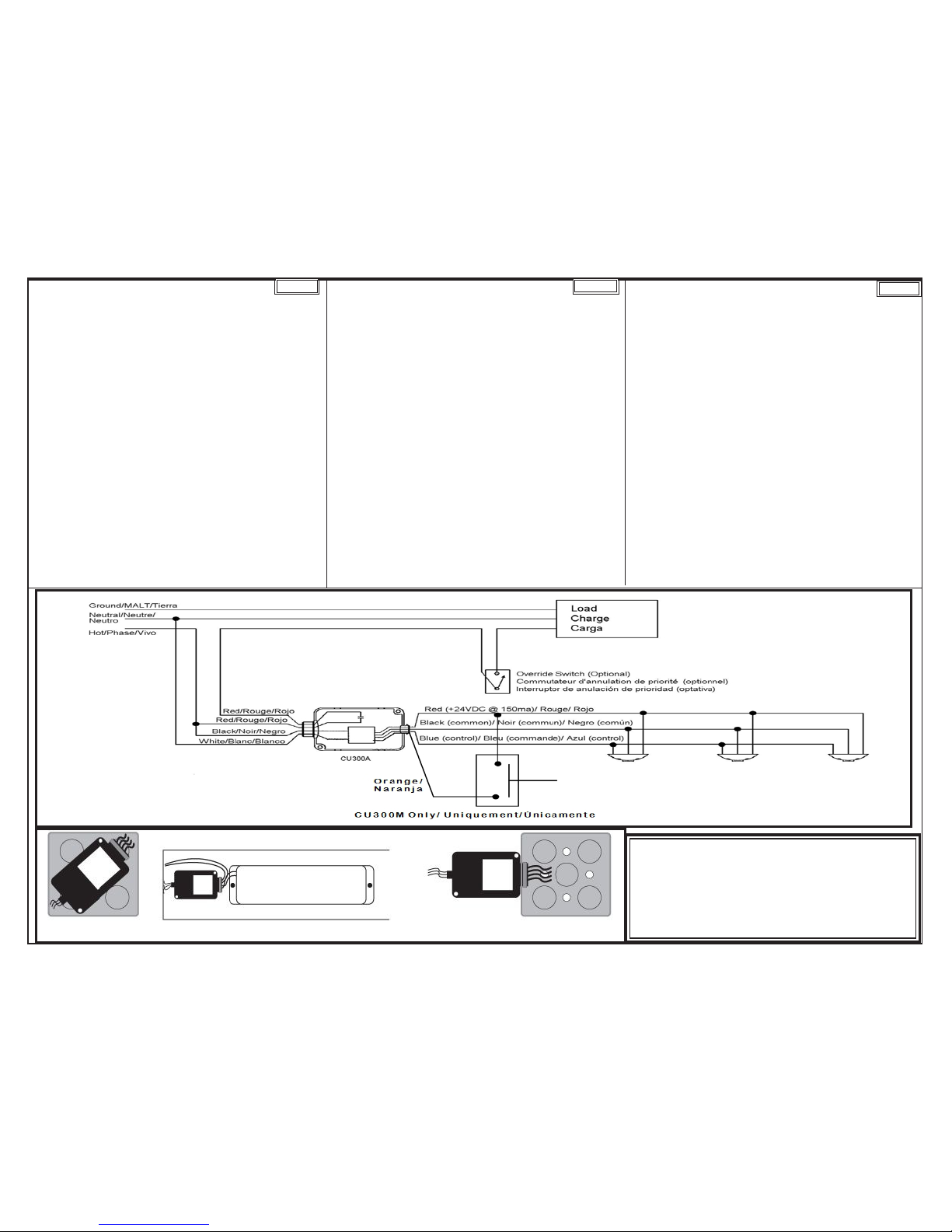
junctionboxknockouts.SeeMounting Diagram.
3.Connect the unit to the circuit as shown in the Wiring
Diagram.
4.Turnpoweronattheservicepanel.
SPÉCIFICATIONS
• Tensiond'entrée:100à267Vca,50/60Hz
• Tensiondesortie:24Vcc,150mA(classe2),protégécontre
lescourts-circuits
• Valeursnominalesdescontactsdurelais:20A,120Vca
incandescent, 20A, 120 ou 277 Vca uorescent, 1 HP,
chargedemoteurde120ou277Vca
• Montageàl'intérieurouàl'extérieurd'uneboîtededérivation
ouàl'intérieurdelacavitéd'unballastd'unuorescent
• Alimentejusqu'à4capteurs
• Homologuépourplénum
AVANT LE MONTAGE
• ATTENTION-RISQUEDECHOCÉLECTRIQUE.Débrancher
lecircuitavantdeprocéderaumontage.Nejamaiscâblerdes
composantsélectriquesdansuncircuitsoustension.
• ATTENTION-Employeruniquementdesconducteursen
cuivre.
• AVIS- Lireetcomprendrelesdirectivesdemontageavant
d'entreprendrelestravaux.
• AVIS- Doitêtreinstalléparunélectricienqualiéconformément
auxcodesdel'électriciténationauxetlocaux.
• AVIS–Pourusageàl'intérieurseulement.
• AVIS- S'assurerquelescaractéristiquesnominalesdece
dispositifconviennentàl'application.
• AVIS - Nepasmonterl’appareilsi l’onydécèledes
dommagesapparents.
INSTALLATION
1.Couperl'alimentationauniveauducoffretdebranchement.
2.Utiliserdesvis6x32àtêtecylindriqueouunécroudeblocage
pourconduitde13mmpourxerl'unitéàl'intérieurd'une
boîtededérivationoudanslacavitéduballastd'unluminaire.
Unmanchonadaptateurbassetension(venduséparément)
permet d'installer l'unité entre les débouchures de deux
boîtesdedérivation.ConsulterleSchéma de montage.
3.Raccorderl'unitéaucircuitconformémentauSchéma de
câblage.
4.Remettre le circuit sous tension à partir du coffret de
branchement.
ESPECIFICACIONES
• Voltajedeentrada:100a277V~,50/60Hz
• Voltajedesalida:V=24,150mA(clase2),protegidacontra
cortocircuitos
• Característicasnominalesdeloscontactosderelé:20A,
120V~incandescente,20A,120V~o277V~uorescente,
1HP,cargademotorde120V~o277V~
• Montajeadentrooafueradeunacajadederivación,oen
lacavidaddeunareactanciadeuorescente
• Alimentahasta4sensores
• Homologadaparaplenos
ANTES DE LA INSTALACIÓN
• ¡CUIDADO!-RIESGODE CHOQUE ELÉCTRICO.
Desconectarlacorrienteantesdelainstalación.Noconectar
nuncacomponenteseléctricosenuncircuitoenergizado.
• ¡CUIDADO! -Utilizarsolamenteconductoresdecobre.
• AVISO - Leer y comprender las instrucciones antes de
instalar.
• AVISO- Paraserinstaladaporunelectricistacalicado,de
acuerdoconloscódigoseléctricosnacionalesylocales.
• AVISO- Exclusivamenteparausoeninteriores.
• AVISO- Asegurarsedequelascaracterísticasnominales
deldispositivoseanapropiadasparalaaplicación.
• AVISO - No instalar si se observa cualquier daño en el
producto.
INSTALACIÓN
1.Cortarlaalimentacióndeenergíaeneltablerodeservicio.
2.Usartornillos6x32decabezachaneadaocontratuercade
conductode13mmparajarlaunidad,sisemontadentro
delacajadederivaciónoenlacavidaddereactanciadeun
artefactodeiluminación.Unaboquillaadaptadoradebaja
tensión(quesevendeaparte)permiteinstalarlaunidad
entredospiezasamoviblesdelacajadederivación.Ver
Diagrama de montaje.
3.Conectar la unidad al circuito como se muestra en el
Diagrama de cableado.
4.Alimentardenuevolaenergíaeneltablerodeservicio.
PD2281 (Page1) 10/11 PRINTEDINUSA