Hubbell Anderson PW115V-HD User manual

Manual M-800 Rev. 6/09Manual M-800 Rev. 6/09
SERVICE AND OPERATION MANUAL
PW115/230V-HD HYDRAULIC POWER PUMP
ELECTRIC
TWO-STAGE HYDRAULIC PUMP
NOTE: Read and carefully follow these instructions. Most problems with
new equipment are caused by improper operation or installation.
To help avoid personal injury:
Hydraulic Hose
• Beforeoperatingthepump,allhoseconnectionsmustbetightened
withthepropertools.Donotovertighten.Connectionsshouldonlybe
tightenedsecurelyandleak-free.Overtighteningcancausepremature
threadfailureorhighpressurettingstosplitatpressureslowerthan
theirratedcapacities.
• Shouldahydraulichoseeverrupture,burst,orneedtobedisconnected,
immediatelyshutoffthepumpandshiftthecontrolvalvetwicetorelease
allpressure.Neverattempttograspaleakinghoseunderpressurewith
yourhands.Theforceofescapinghydraulicuidcouldcauseserious
injury.
• Donotsubjectthehosetopotentialhazardsuchasre,sharpsurfaces,
extremeheatorcold,orheavyimpact.Donotallowthehosetokink,
twist,curl,orbendsotightlythattheoilowwithinthehoseisblocked
orreduced.Periodicallyinspectthehoseforwear,becauseanyofthese
conditionscandamagethehoseandresultinpersonalinjury.
• Donotusethehosetomoveattachedequipment.Stresscandamage
thehoseandcausepersonalinjury.
• Hosematerialandcouplersealsmustbecompatiblewiththehydraulic
uidused.Hosesalsomustnotcomeincontactwithcorrosivematerials
suchascreosote-impregnatedobjectsandsomepaints.Consultthe
manufacturerbeforepaintingahose.Neverpaintthecouplers.Hose
deteriorationduetocorrosivematerialscanresultinpersonalinjury.
WARNING
!
Page 1 of 16Page 16 of 16
HMIS(US): HealthHazard 1
FireHazard 1
Reactivity 0
PersonalProtection 8
NFPA(USA): HealthHazard 1
FireHazard 1
Reactivity 0
SpecicHazard none
Rating 0 Insignicant
1 Slight
2 Moderate
3 High
4 Extreme
Section 16. Other Informations
Preparedby: SPXFluidPower
588511thStreet
Rockford,IL61109,USA
Phone:815-874-5556
Fax:815-874-7886
Dateofpreparation:November,2007
Theinformationpresentedhereinhasbeen
compiledfromsourceconsideredtobedepend-
ableandaccuratetothebestofSPXFluidPower
knowledge;however,SPXFluidPowermakes
nowarrantywhatsoever,expressedorimplied,
ofMerchantabilityorFitnessfortheParticular
Purpose,regardingtheaccuracyofsuchdataor
theresultstobeobtainedfromtheuserthereof.
SPXFluidPowerassumesnoresponsibilityforthe
injurytorecipientortothethirdpersonsorforany
damagetoanypropertyandrecipientassumesall
suchrisks.
Rev.2
Material Safety Data Sheet
Material Safety Data Sheet Page 3
AW Hydraulic Oil ISO 46
SAFETY PRECAUTIONS
HUBBELL®
Power Systems

Manual M-800 Rev. 6/09Manual M-800 Rev. 6/09
Pump
• DonotexceedthePSIhydraulicpressureratingnotedonthepump
nameplateortamperwiththeinternalhighpressurereliefvalve.
Creatingpressurebeyondratedcapacitiescanresultinpersonalinjury.
• Beforereplenishingtheoillevel,retractthesystemtopreventoverlling
thepumpreservoir.Anoverllcancausepersonalinjuryduetoexcess
reservoirpressurecreatedwhencylindersareretracted.
Cylinder
• Donotexceedratedcapacitiesofthecylinders.Excesspressurecan
resultinpersonalinjury.
• Donotsetpoorly-balancedoroff-centerloadsonacylinder.Theload
cantipandcausepersonalinjury.
Power Supply (Electric)
• IMPORTANT:Inordertomeetcertain
electricalsafetyrequirements,pumpsin
thisserieswiredfor115VoltAC60Hz
arerequiredtocontaina20AMPplug
asshowntotheright.Plugunitintothe
appropriate20AMPelectricalfemale
receptacle.Donotmodifythepump
powercordorpluginanyway-doingso
willVOIDtheproductwarrantyonany
electricalcomponents.
• Donotuseanungrounded(two-prong)extensioncordwiththisunit.
• Avoidanyconditionsthatcouldcreateanelectricalhazard.
• Anyelectricalworkmustbedonebyaqualiedelectrician.
• Ifthepowercordisdamagedorwiringisexposed,replaceorrepair
immediately.
• Disconnectthepowersupplybeforeremovingthemotorcontrolbox
coverorperformingrepairsormaintenance.
• Pumpmustbepluggedintocorrespondingvoltagepowersource.
• Branchcircuitmustbesizedproperlyforproperoperationofpump.For
bestperformance,plugpumpintoacircuitratedequaltoorgreaterthan
themaximumampratingorpump.
• Ifbranchcircuitbreakerorfuseopenscontinuously,donotattemptto
increasethepowerlinecapacitybyreplacingafuseorbreakerwith
anotherofhighervalue.Overheatingofthepowerlineandpossibilityof
arewillresult.
WARNING (cont’d)
!
Page 2 of 16 Page 15 of 16
Section 8. Exposure Control / Personal Protec-
tion
EngineeringControls:Fornormalapplication,
specialventilationisnotnecessary.Ifuser’s
operationsgeneratevaporsormists,useventila-
tiontokeepcontaminantsbelowexposurelimits.
Make-upairshouldalwaysbesuppliedtobalance
airremovedbyexhaust.Haveeyewashstationand
safety-showerclosetoworkstation.
PersonalProtection:
Eyes:Eyeprotectionshouldbedeterminedbased
onconditionsofuse.Ifproductisusedinapplica-
tionwheresplashingmayoccur,theuseofsafety
gogglesand/orafaceshieldshouldbeconsidered.
HandsandBody:Wearappropriatechemically
protectiveglovesandwearappropriateclothingto
preventskincontact.
Respiratory:NIOSHapprovedrespiratorsshould
beusedwhenairbornecontaminationisabove
exposurelimits.
Feet:Wearappropriatefootweartopreventproduct
fromcomingincontactwithfeetandskin.
Section 9. Physical and Chemical Properties
Appearance,PhysicalState:Clear,Blue,Viscous
Liquid
Odor:Mildpetroleum
Viscosity:41.4-50.6cSt@40degC
FlashPoint:>=200deg.C(392deg.F)
Vaporpressure:Negligibleatambienttemperature
andpressure
SpecicGravity:0.875kg/L@20deg.C(68deg.
F)
Watersolubility:Insolubleinwater
pH:Notapplicable
Section 10. Stability and Reactivity
Stability:Stableundernormalhandlingandstorage
condition
HazardousPolymerization:Willnotoccuratnormal
workingconditions.
IncompatibleSubstances/ConditionstoAvoid:
Reactivewithoxidizingagentsandacids.
DecompositionProducts:Combustioncanyield
carbon,nitrogen,sulfur,phosphorus,andzinc
oxides.
Section 11. Toxicological Information
Routesofentry:Skinandeyecontact,inhalation,
ingestion.
AcuteLethality:Basedontoxicityofcomponents.
Acuteoraltoxicity(LD50):>2000mg/kgrat.
ChronicorOtherToxicEffects.
DermaRoute:Prolongedorrepeatedcontactmay
causeskinirritationcharacterizedbydermatitisor
oilacne.
InhalationRoute:Negligiblebreathinghazardat
normaltemperature.Elevatedtemperaturesorme-
chanicalactionmayformvapors,mistsorfumes.
Material Safety Data Sheet
Material Safety Data Sheet Page 2
AW Hydraulic Oil ISO 46
Inhalationofoilmistsorvaporsfromhotoilmay
causeirritationoftheupperrespiratorytrack.
OralRoute:Lowtoxicity.
EyeIrritation/Inammation:Repeatedor
prolongedcontactmaycauseirritationbutnot
permanentdamage.
Immunotoxicity:Notavailable.
SkinSensitization:Notexpectedtobeskinsen-
sitizer.
RespiratoryTractSensitization:Notexpectedtobe
respiratorytractsensitizers.
Carcinogenicity:Thisproductisnotknowntocon-
tainanychemicalsatreportablequantitiesthatare
listedascarcinogensbyNTP,IARC,OSHA.
OtherConsiderations:Noadditionalremark.
Section 12. Ecological Information
EnvironmentalFate:Notavailable.
Persistence/BioaccumulationPotential:Not
available.
BOD5andCOD:Notavailable.
ProductofBiodegradation:Notavailable.
AdditionalRemarks:Noadditionalremarks.
Section 13. Disposal Considerations
WasteDisposal:Spent/usedwasteoilmaymeet
therequirementsofahazardouswaste.Con-
sultyourlocalorregionalauthorities.Preferred
wastemanagementprioritiesare:(1)recycleor
reprocess,(2)incineratewithenergyrecovery,(3)
disposalatlicensedwastedisposalfacility.Ensure
thatdisposalorreprocessingisincompliance
withgovernmentrequirementsandlocaldisposal
regulations.
Section 14. Transport Information
TDGClassication:NotcontrolledunderTDG
(Canada).
DOTShippingDescription:Notclassiedas
hazardous.
SpecialProvisionsforTransport:Notapplicable
Section 15. Regulatory Information
Thisproductisacceptableforuseunderthe
provisionsofWHMIS-CPR.Allcomponentsofthis
formulationarelistedontheCEPA-DSL.(Domestic
SubstancesList).
Allcomponentsofthisformulationarelistedonthe
USEPA-TSCAInventory.
Thisproducthasbeenclassiedinaccordance
withthehazardcriteriaoftheControlledProducts
Regulations(CPR)andtheMSDScontainsallof
theinformationrequiredbytheCPR.
Thisproductisnotknowntocontainanychemicals
atreportablequantitiesthatarelistedontheSARA
313and40CFR372.
ThisproductisnotcontrolledundertheHCS.

Manual M-800 Rev. 6/09Manual M-800 Rev. 6/09 Page 3 of 16
OPERATING PROCEDURE
Filling the Reservoir
NOTE: The pump has been shipped without oil in the reservoir. A high-
quality, approved hydraulic oil has been shipped with the pump in a
separate container. If additional oil is required, use an approved hydraulic
oil only.
1. Cleantheareaaroundthellercaptoremovealldustandgrit.Anydirtordust
intheoilcandamagethepolishedsurfacesandprecision-tcomponentsof
thispump.
2. Retractallcyclinder(s)totheirreturnposition.
3. Removethellercapandinsertacleanfunnelwithalter.Fillthereservoir
withahigh-quality,approvedhydraulicoiltowithin1”ofthecoverplate.
Replacethellercap.
4. Cyclethepump(withthecylinder(s)attached)severaltimes.Retractthe
cylinder(s)andchecktheoillevelinthepumpreservoir.
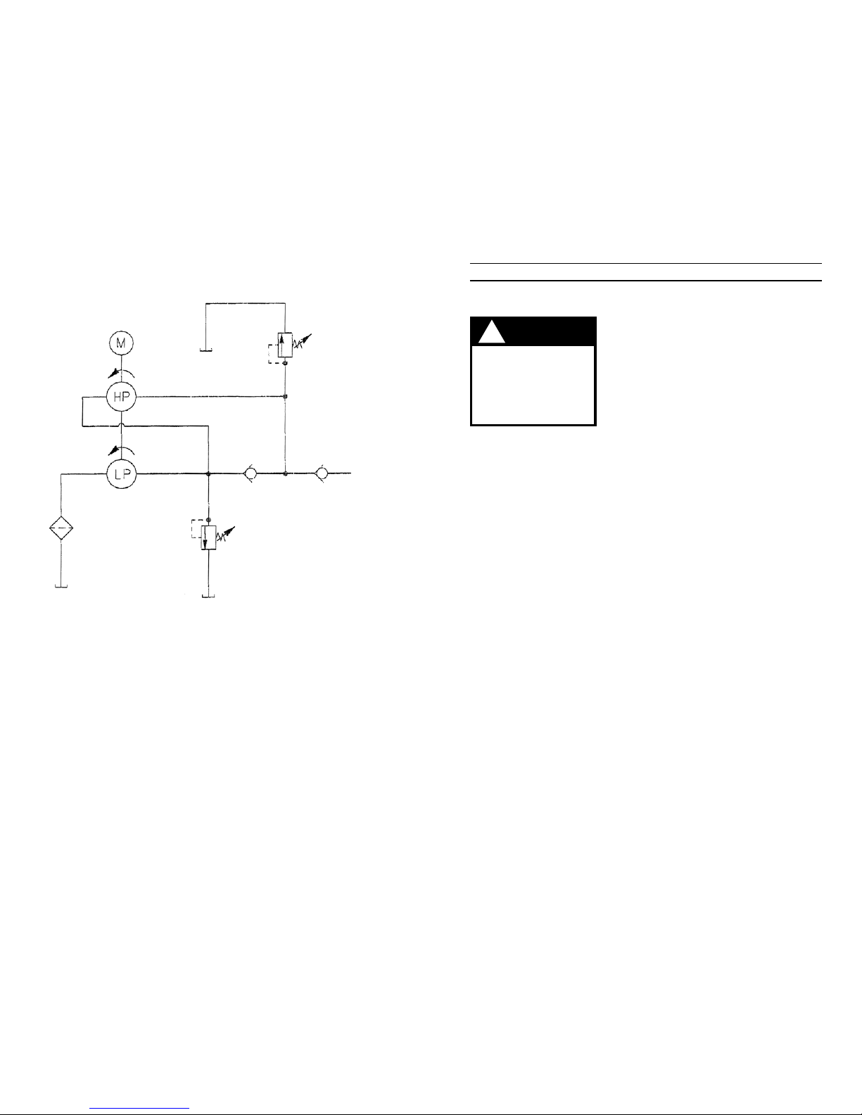
Electrical Hook-up and Operation
To help avoid personal injury:
• Allelectricalworkmustbedonebyaqualiedelectrician.
• Disconnectthepowersupplybeforeremovingmotorcasingcoveror
performingrepairsormaintenance.
• Allvoltagesmustbewiredforcounterclockwiserotationwhenviewed
fromtheleadendofthemotor.
• Changingthevoltageonthisunitisaninvolved,andifproperly
performed,hazardousprocedure.Consultthemanufacturerforspecic
informationbeforeattemptinganyrewiring.
WARNING
!
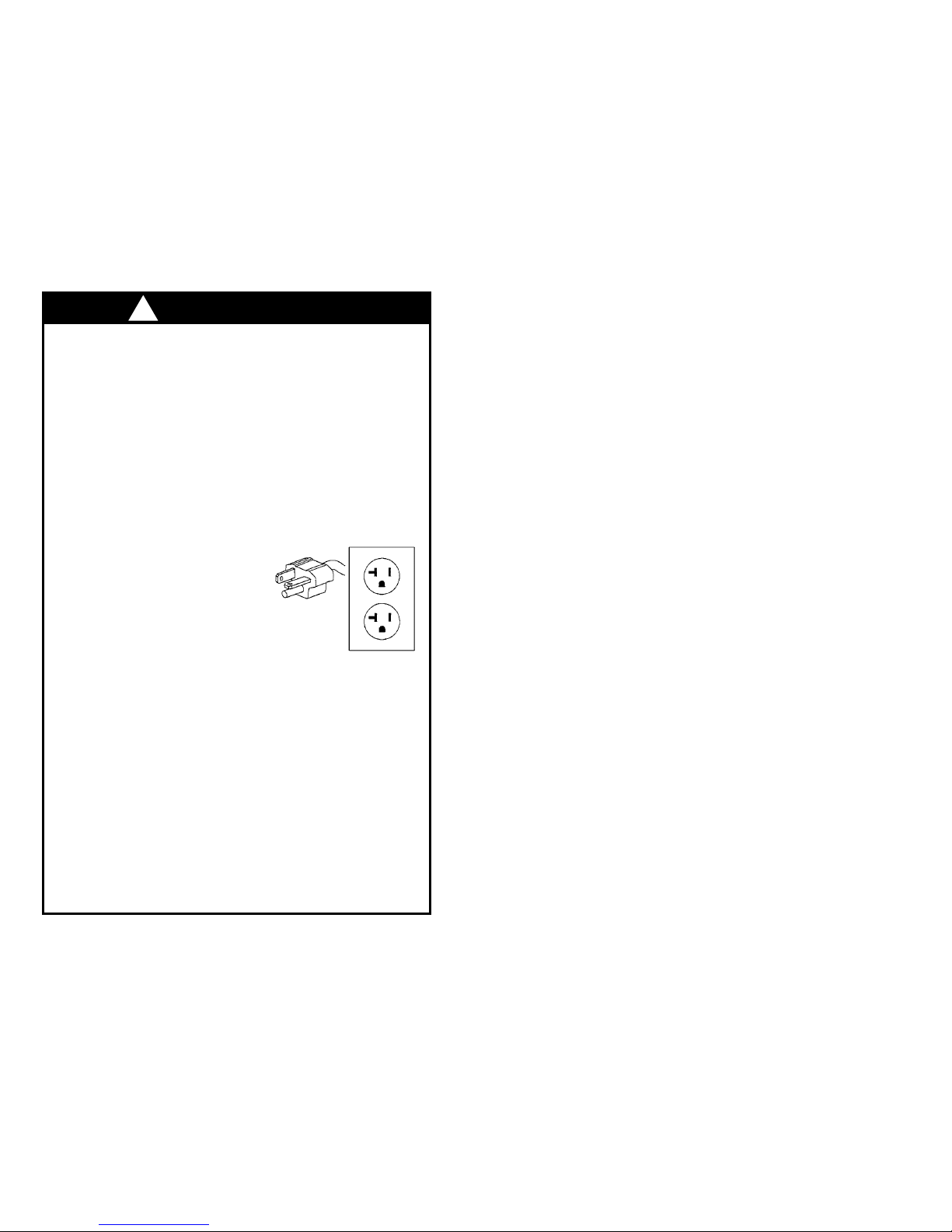
1. Theelectricmotorisasinglephase,60cycleandcanbewiredat115or230
volts.
Page 14 of 16
Material Safety Data Sheet
Section 1. Chemical Product and Company
Identifcation.
ProductName:AW Hydraulic Oil ISO 46
Code/PartNumber:9636,9637,9638,9616,
11360,9647
Manufacturer: SPXFluidPower
588511thStreet
Rockford,IL61109,USA
Phone:815-874-5556
CHEMTREC 24 Hr. Emergency Number:
800-424-9300
MaterialUse: Theproductdesignedforusein
heavydutyHydraulicuid
applications.
ValidatedonJanuary,2007
Section 2. Composition and Information on
Ingredients.
Name:Hydrotreatedorseverelyrenedbaseoil
andproprietaryadditivesCAS#:Mixture
%(V/V):100
ExposureLimits:
TLV-TWA(8hr):5mg/cubicm(oilmist)
STLE:10mg/cubicm(oilmist)
ManufacturerRecommendation:Notapplicable
OtherExposureLimits:Consultlocal,state,
provincialorterritorialauthoritiesforacceptable
exposurelimits.
Section 3. Hazardous Identification.
Potentialhealtheffects:Notirritatingtoslightirrita-
tiontoskinandeyeswithnopermanentdamage.
Relativelynon-toxicviaingestion.Thisproducthas
alowvaporpressureandisnotexpectedtopres-
entaninhalationexposureatambientconditions.
Athightemperaturesormechanicalactionsmay
producevaporsormists.Inhalationmaycauseir-
ritationofthebreathingpassages.Seesection11.
Section 4. First Aid Measures
Eye contact:Immediatelyusheyeswithrunning
waterforatleast15minutes,keepingeyelids
open.Seekmedicalattention.
Skin Contact:Removecontaminatedclothing–
launderbeforereuse.Washcontaminatedskin
withrunningwaterandnon-abrasivesoap.Get
medicalattentionifirritationdevelopsorifproduct
isinjectedunderpressureintoorundertheskin.
Inhalation:Removetofreshair.Getmedicalat-
tentionifbreathingdifcultypersists.Ifvictimisnot
breathing,performarticialrespiration.
Ingestion:DONOTinducevomiting.Seekmedi-
calattention.
Section 5. Fire-Fighting Measures
Flammability:Maybecombustiveathightempera-
ture.
Flashpoint:>=200degC(392degF)(COC)
FlammableLimits:Notavailable
Auto-IgnitionTemperature:Notavailable
FireHazardinPresenceofVariousSubstances:
Lowrehazard.Thismaterialmustbeheated
beforeignitionwilloccur.
ExplosionHazardsinPresenceofVariousSub-
stances:Donotcut,weld,drillorpressurizeempty
container.Containersmayexplodeinheatofre.
ProductsofCombustion:variousoxidesofcarbon,
nitrogen,sulfur,smokeandirritatingvaporsfrom
incompletecombustion.
FireFightingMediaInstructions:NAERG96,Guide
171,Substances(lowtomoderatehazard).Iftank,
railcarortankisinvolvedinre,ISOLATEfor800
meters(0.5mile)inalldirections.Shutofffuelto
reifitispossibletodowithouthazard.ifitisnot
possible,withdrawfromareaandletreburnout
undercontrolledconditions.Withdrawimmediately
incaseofrisingsoundfromventingsafetydevice
oranydiscolorationoftankduetore.Coolcon-
tainingvesselswithwatersprayinordertoprevent
pressurebuild-up,autoignitionorexplosion.
SmallFire:useDRYchemicals,foam,waterspray
orCO2.
LargeFire:usewaterspray,fogorfoam.Forsmall
outdoorres,portablereextinguishersmaybe
used.Forallindoorresandsignicantoutdoor
resself-containedbreathingapparatusisre-
quired.Respiratoryandeyeprotectionarerequired
forreghtingpersonnel.
Section 6. Accidental Release Measures
MaterialReleaseorSpill:NAERG96,Guide171,
Substances(lowtomoderatehazard).ELIMINATE
ALLIGNITIONSOURCES.Avoidcontact.Stop
leakifwithoutrisk.Containspill.Absorbwithinert
absorbents.Placeusedabsorbentinclosedmetal
containersforlaterdisposalorburnabsorbentin
suitablecombustionchamber.DONOTFLUSH
TOSEWERS,STREAMSOROTHERBODIESOF
WATER.Checkwithapplicablejurisdictionforspe-
cicdisposalrequirementsofspilledmaterialsand
emptycontainers.Notifytheappropriateauthorities
immediately.
Section 7. Handling and Storage
Handling:Avoidinhalationandskincontact
especiallywhenhandlingusedoil.Keepawayfrom
sourcesofignition.Donotreuseemptycontain-
erswithoutcommercialreconditioning.Practice
goodpersonalhygiene.Washhandsafterhandling
oilandbeforeeating.Launderworkclothesfre-
quently.Discardsaturatedleathergoods.
Storage:Storeintightlyclosedcontainersincool,
dry,isolated,well-ventilatedarea,andawayfrom
incompatibles.
Material Safety Data Sheet Page 1
AW Hydraulic Oil ISO 46

Manual M-800 Rev. 6/09Manual M-800 Rev. 6/09
Pump Operation
Whenoperatingthepumpforthersttime:
1. Allvalveandhoseconnectionsshouldbesecure,andthereservoirshouldbe
lledtotheproperlevel.Connectthepowersupply.
2. Activatethepump,andadvancethecylinder(s)bypushingtheUPbutton
ontheremotecontrolswitch.ThemotorshutsoffwhentheUPbuttonis
released,andsystempressureisheld.PresstheDOWNbuttonorshiftthe
manualvalvetoallowthecylinder(s)toretract.
3. Refertothesectiontitled“BleedingAirfromtheSystem.”
4. Checktheoillevelinthereservoirandaddoilifnecessary.Thereservoiroil
levelshouldbewithin1”ofthepumpcoverplate.
PRESSURE REGULATING CONTROL ADJUSTMENTS
(NOTE: These options are not on all pump models.)
Adjusting the Pressure Regulating Valve
Thepressureregulatingvalvecanbeadjustedtobypassoilatagivenpressure
whilethepumpcontinuestorun.
IMPORTANT:
• Foreasyadjustmentofthepressureregulatingvalve,alwaysadjustthe
pressure by increasing it to a desired pressure setting.The pressure
range for this unit is from 1,000 PSI to 10,000 PSI.
1. Loosenthelocknutonthepressureregulatingvalve,andturntheadjusting
screwafewturnscounterclockwise(CCW)todecreasethepressuresetting
toalowerthandesiredpressure.
2. Connectthepumpcompletely.PlacethemotorcontrolswitchintheRun
positionandpushtheStartbutton.
3. Slowlyturntheadjustingscrewinaclockwise(CW)directiontogradually
increasethepressuresetting.Whenthedesiredpressuresettingisreached,
locktheadjustingscrewintopositionbytighteningthelocknut.
Page 4 of 16
OPERATING INSTRUCTIONS
Hydraulic Connections
1. Cleanalltheareasaroundtheoilportsofthepumpandcylinder(s).
2. Inspectallthreadsandttingsforsignsofwearordamage,andreplaceas
needed.
3. Cleanallhoseends,couplers,orunionends.
4. Removethethreadprotectorsfromthehydraulicoiloutlets.
5. Connectthehoseassemblytothehydraulicoiloutlets,andcouplethehoseto
thecylinder.
IMPORTANT: Seal all external pipe connections with a high-quality,
non-hardening thread sealant.Teflon tape can be used to seal hydraulic
connections if only one layer of tape is used. Apply the tape carefully,
two breads back, to prevent it from being pinched by the coupler and
broken off inside the system. Any loose pieces of tape could travel
through the system and obstruct the flow of oil or cause jamming of
precision-fit parts.
RECOMMENDED MINIMUM WIRE SIZE-AWG (mm2)
OF EXTENSION CORDS FOR ELECTRIC PUMPS
Current
At Full Load
(Amps)
Cord Size AWG (mm2) 3.2 Volt Drop
Length of Cord
0-25 feet
(0-8 m)
25-50 feet
(8-15 m)
50-100 feet
(15-30 m)
100-150 feet
(30-45 m)
6 18(.82) 16(1.33) 14(2.09) 12(3.32)
8 18(.82) 16(1.33) 12(3.32) 10(5.37)
10 18(.82) 14(2.09) 12(3.32) 10(5.37)
12 16(1.33) 14(2.09) 10(5.37) 8(8.37)
14 16(1.33) 12(3.32) 10(5.37) 8(8.37)
16 16(1.33) 12(3.32) 10(5.37) 8(8.37)
18 14(2.09) 12(3.32) 8(8.37) 8(8.37)
20 14(2.09) 12(3.32) 8(8.37) 6(13.30)
22 14(2.09) 10(5.37) 8(8.37) 6(13.30)
24 14(2.09) 10(5.37) 8(8.37) 6(13.30)
26 12(3.32) 10(5.37) 8(8.37) 6(13.30)
28 12(3.32) 10(5.37) 6(13.30) 4(21.29)
30 12(3.32) 10(5.37) 6(13.30) 4(21.29)
Page 13 of 16

Manual M-800 Rev. 6/09Manual M-800 Rev. 6/09
Cylinder(s) will not retract. 1.Checkthesystempres-
sure;ifthepressureis
zero,thesolenoidvalve
isreleasingpressure
andtheproblemmaybe
inthecylinder,(mechan-
icallinkageconnectedto
cylinders),orquick-
disconnectcouplings.
2.Defectivevalve.
1.Checkthecylindersfor
brokenreturnsprings
andcheckcouplers
toinsurethattheyare
completelycoupled.
Occasionallycouplers
havetobereplaced
becauseonecheckdoes
notstayopeninthe
coupledposition.
2.Checkvalveoperation
andinspectparts.
Replaceifnecessary.
PROBLEM CAUSE SOLUTION
Pump delivers excess oil
pressure.
1.Checkpressuregauge.
2.Reliefvalvenotproperly
set.
1.Calibrategauge.
2.Resetthereliefvalve.
Automatic valve will not build
full pressure.
1.Unloadingpressureis
toolow.
2.Defectiveoroversize
seatonautomaticvalve.
1.Increaseunloading
pressure.
2.Replaceballandseat.
Page 12 of 16 Page 5 of 16
Pressure Regulating Valve
Apressureswitchcanbeadjustedtostopthepumpmotoratadesiredpressure
settingandrestartthemotorwhenthepressurefallsbelowthatsetting.
Itisrecommendedthatapressureswitchbeusedwithapressureregulating
valvetoinsureaccuracywhensettingamaximumPSIlevel.Apressure
switchalonewillbreakthemotor’senergysupplyataselectedsetting,butthe
hydraulicpumpwillcontinuebuildingpressureasitslowstoastop.Thepressure
regulatingvalveisadjustedatasettingslightlyabovethepressureswitchsetting
tocompensatebyreleasingthepressuredevelopedbythehydraulicpumpas
it“coasts”toastop.Asaresult,thepressurelimitrequirementcanbeheldto
approximately300PSI.
Adjusting the Pressure Switch Setting
1. Loosenthelocknutonthepressureswitch.Slowlyturnthepressureswitch
adjustingscrewinacounterclockwise(CCW)direction,decreasingthe
pressureswitchsettinguntilthepumpmotorshutsoff.Tightenthelocknutto
locktheadjustingscrew.
2. Releasethehydraulicpressure.Runthepumptocheckthepressuresetting
andautomaticshutoffofthemotor.Itmaybenecessarytomakeasecond
neadjustment.
To help avoid personal injury:
• Disconnectthepumpfromthepowersourcebeforeperforming
maintenanceorrepairprocedures.
• Maintenanceandrepairsmustbeperformedinadust-freeareabya
qualiedtechnician.
WARNING
!
Bleeding Air from the System
Uponinitialstartuporafterprolongeduse,aircanaccumulatewithinthe
hydraulicsystem.Thisentrappedaircancausethesystemtorespondslowlyor
behaveinanunstablemanner.Toremovetheair,loosenattingthatissituated
higherthantherestofthettingsinthesystem.Runthepumpuntilasteadyow
ofoilfreeofsuspendedairbubblesisobserved.Tightenthetting.
Inspecting the Hydraulic Fluid Level
Checktheoillevelinthereservoirperiodically.Theoillevelshouldcometo
within1”ofthepumpcoverplatewithallcylindersretracted.Drain,cleanand
replenishthereservoirwithahigh-quality,approvedhydraulicoilyearlyormore
oftenifnecessary.Thefrequencyofoilchangewilldependuponthegeneral
workingconditions,severityofuseandoverallcleanlinessandcaregiventhe
pump.
PREVENTIVE MAINTENANCE

Manual M-800 Rev. 6/09Manual M-800 Rev. 6/09 Page 11 of 16
PROBLEM CAUSE SOLUTION
Pump builds pressure but
cannot maintain pressure.
1.Checktoseeifthereare
anyexternalleaks.Ifno
oilleakageisvisible,the
problemisinternal.
2.Totestforaleaking
controlvalve,liftthe
pumpfromthereservoir
butkeepthelterinthe
oil.Removethedrain
linetoseeiftheoilis
leakingfromthevalve.If
thevalveisnotleaking,
theinternalcheckvalve
couldbeleaking.Refer
tothenoteconcerning
checkingforoilleaks
atthebeginningofthis
TroubleshootingGuide.
1.Resealleakingpipet-
tingswithpipesealant.
2.Clean,reseatorreplace
controlvalveparts.Ifthe
internalcheckvalveis
leaking,thecheckvalve
mustbedisassembled
andtheseatareare-
paired,poppetreplaced,
etc.
Pump will not build full
pressure.
1.Faultypressuregauge.
2.Checkforexternal
leakage.
3.Checkthereliefvalve
setting.
4.Checkforleaksinthe
solenoidvalve.
5.Inspectthepumpfor
internalleakage.Check
highpressurepumpinlet
oroutletballchecks.
6.Shearedkey(s).
7.Automaticvalveleakage.
1.Calibrategauge.
2.Sealanyfaultypipet-
tingwithpipesealant.
3.Liftthepumpfromthe
reservoirbutkeepthe
lterimmersedinoil.
Notethepressureread-
ingwhenthereliefvalve
beginstoopenup.If
functioningnormally,it
shouldstarttoleakoff
justpriortoreliefvalve
pressure.
4.Cleanandreseator
replaceparts.
5.Sameprocedureas
abovebutlookforleaks
aroundtheentireinner
mechanism.Ifthereare
novisibleleaks,thehigh
pressurepumpsubas-
semblymaybeleaking.
Removeallparts.Check
thevalveheadassembly
foranydamagetothe
seatarea.Cleanand
reseatifnecessary.
Inspectfordamageand
replacepartsifneces-
sary,thenreassemble.
6.Replaceafterchecking
pumpcavityforbroken
pieces.
7.Checkautomaticvalve
seat.
Adding Oil to the Reservoir
1. Cylinder(s)mustbefullyretractedandthepowersupplydisconnectedwhen
addingoiltothereservoir.
2. Cleantheentireareaaroundthellercapbeforeremovingthecap.
3. Useacleanfunnelwithlterwhenaddingoil.
4. Useonlyapprovedhydraulicuids.
Maintenance Cleaning
1. Keeptheoutersurfaceofthepumpasfreefromdirtaspossible.
2. Protectallunusedcouplers.
3. Keepallhoseconnectionsfreeofdirtandgrime.
4. Keepthebreatherholeinthellercapcleanandunobstructedatalltimes.
5. Equipmentconnectedtothepumpmustbekeptclean.
6. Useonlyapprovedhydraulicuidsinthispump.Changeasrecommended.
Draining and Cleaning the Reservoir
IMPORTANT: Clean the pump exterior before the pump interior is removed
from the reservoir.
1. Removethescrewsthatfastenthemotorandpumpassemblytothereservoir.
IMPORTANT: Lift the pump and motor off the reservoir carefully to avoid
damaging the gasket or any internal components.
2. Cleantheinsideofthereservoirandllhalffullwithcleanhydraulicuid.
3. Placethepumpandmotorassemblybackontothereservoirandsecure
withtwomachinescrewsassembledonoppositecornersofthehousing.
IMPORTANT: Connect a hose to the pressure port on the valve. Place the
other end of the hose into the oil filler hole.
4. Runthepumpforseveralminutes.Thendisconnectthemotorandpump
assembly,anddrainandcleantheinsideofthereservoir.
5. Fillthereservoirwithahigh-quality,approvedhydraulicuid.Placethepump
andmotorassembly(withgasket)onthereservoirandinstallallthescrews.
Tightensecurelyandevenly.
Page 6 of 16

Manual M-800 Rev. 6/09Manual M-800 Rev. 6/09 Page 7 of 16
TROUBLESHOOTING
To help prevent personal injury, any repair work or troubleshooting
must be done by qualified personnel familiar with this equipment.
WARNING
!
NOTE:
• Usethepropergaugesandequipmentwhentroubleshooting.
• Itisbesttocheckforleaksbyusingahandpumpandapplyingpressure
to the suspect area without the motor running. Watch for leaking oil and
follow it back to its source.
• Plugtheoutletportsofthepumpwhencheckingforleakageto
determine if the leak is in the pump or elsewhere in the system.
• Refertoyourpump’sappropriatepartslistandthehydraulicand
electrical schematics when using this troubleshooting guide.
North American & International Color Codes
Conductors North American International
Line................................Black......................Brown
Neutral...........................White.....................Blue
Ground.......................... Green.....................Green/Yellow
Page 10 of 16
Pump is not delivering oil or
delivers only enough oil to
advance ram(s) partially or
erratically.
1.Oilleveltoolow.
2.Loosettingcouplerto
ram.
3.Airinthesystem.
4.Airleakinsuctionline.
5.Dirtinpumporlter
plugged.
6.Coldoiloroilistoo
heavy(Hydraulicoilisof
ahigherviscositythan
necessary).
7.Reliefvalveorlow
pressureunloadingvalve
outofadjustment.
8.Reservoircapacityistoo
smallforthesizeofthe
ram(s)used.
9.Defectivedirectional
valve.
10.Releasepoppetnot
seatinginsolenoid
valve.
11.Sheareddriveshaft
key(s).
12.Motorrotatinginwrong
direction.
13.Vacuuminreservoir.
14.Lowpressurepump
worn.
1.Fillreservoirtowithin1”
ofllerplugwithallrams
retracted.
2.Checkquick-disconnect
couplingstorams.
Inspectcouplersto
insurethattheyare
completelycoupled.
Occasionallycouplers
havetobereplaced
becausetheballcheck
doesnotstayopendue
towear.
3.Bleedthesystem.
4.Checkandtightenthe
suctionline.
5.Pumpltershould
becleanedand,if
necessary,pumpshould
bedismantledandall
partsinspectedand
cleaned.
6.Changetolighteroil.
7.Readjustasneeded.
8.Usesmallerram(s)or
largerreservoir.
9.Inspectallpartscarefully
andreplaceifnecessary.
10.Disassemble,inspect,
andcleanpumpto
removeanydirt.
11.Replaceafterchecking
pumpcavityforbroken
pieces.
12.Refertoelectrical
schematiconmotor.
13.Checkforpluggedvent
inllerplug.
14.Repairorreplacegerotor
pump.
The force of escaping
hydraulic fluid could
cause serious injury.
Keep hands, face, etc.
clear of any hydraulic
leaks.
WARNING
!
PROBLEM CAUSE SOLUTION

Manual M-800 Rev. 6/09Manual M-800 Rev. 6/09
HYDRAULIC SCHEMATIC
MAX. PRESSURE
SAFETY RELIEF VALVE
REFER TO YOUR
PUMP’SNAMEPLATE
SUPERCHARGE
RELIEF VALVE
260 / 280 PSI
TO VALVE
Page 8 of 16
PROBLEM CAUSE SOLUTION
Electric motor does not run. 1.Unitisnotpluggedin.
2.Novoltagesupply.
3.Brokenleadwireorde-
fectivepowercordplug.
4.Defectiveswitches.
5.Defectivestartedrelay.
6.Defectiveremoteswitch.
7.Circuitbreakertripped
becausetotalamperage
drawtoohighforexisting
circuit.
8.Overheatedmotor.
9.Faultythermalprotector.
10.Defectivemotor
1.Pluginunit.
2.Checklinevoltage.
Checkresetbuttonon
powerpanel.
3.Replacedefectiveparts.
4.Replaceswitches.
5.Replacedefectiveparts.
6.Replaceremoteswitch.
7.Addanadditionalcircuit
orusealternatecircuit.
8.Waitformotortocool
beforerestarting.
Thermalprotectorwill
resetautomatically,or
pushredresetbutton
ontipofthemotor(ifso
equipped).
9.Replace.
10.Replaceorrepairmotor.
Disconnect power sup-
ply before removing
cover. Any electrical
work should be per-
formed by a qualified
electrician.
WARNING
!
Page 9 of 16
This manual suits for next models
1
Table of contents