Hubbell Dual-Lite Trident TRF 924 User manual

003-2603
TRIDENT TRF 924
65-125kVA Transformer Cabinet
USER MANUAL

Page | ii
No reproduction of any part of this manual, even partial, is permitted without the
authorization of Dual-Lite. Dual-Lite reserves the right to modify the product described
herein, in order to improve it, at any time and without notice.
Hubbell Lighting, Inc
701 Millennium Blvd
Greenville, SC 29607
Web site: www.dual-lite.com/
Thank you for choosing our product.

Page | iii
SAFETY WARNINGS
IMPORTANT SAFETY INSTRUCTIONS
SAVE THESE INSTRUCTIONS
This manual contains important instructions that you should follow during installation and
maintenance of the transformer cabinet. Please read all instructions before operating the
equipment and save this manual for future reference.
READ AND FOLLOW ALL SAFETY INSTRUCTIONS
Do not use outdoors.
Do not route wiring across or near hot surfaces.
Do not install near gas or electric heaters.
Equipment should be installed where it will not readily be subjected to tampering by
unauthorized personnel.
The use of accessory equipment not recommended by the manufacturer may cause
an unsafe condition.
Do not use this equipment for other than intended use.
This equipment connects to the output of an uninterruptible power supply.
Hazardous voltages may be present even when the electrical supply to this
equipment is turned off.
If equipped with a maintenance bypass switch, control connections between this
equipment and the ups must be present to prevent the possibility of backfeed.
Read and follow the instructions that came with the associated UPS or emergency
lighting system before operating this equipment.
Table 1 - Symbols
Danger / Risk of Electric Shock
This symbol indicates possibility of serious injury or substantial
damage to the unit, unless adequate precautions are taken.
Warning
This symbol indicates important information which must be
understood and any stated precautions taken
Note

Page | iv
This equipment contains lethal voltages. All repairs and service should only be
performed by authorized service personnel. There are no user serviceable parts
inside this equipment. Operation of switches and breakers require access to the
cabinet interior and should only be performed by qualified personnel exercising
appropriate caution.
This equipment connects to the output of a UPS which contains its own energy
source (batteries). The UPS output may carry live voltage even when the UPS is
not connected to an AC supply.
To reduce the risk of fire and electric shock, install this equipment in a humidity
controlled, indoor environment, free of conductive contaminants. Do not operate
near water or excessive humidity (95% maximum). If condensation is present, the
equipment must be allowed to completely dry before operation.
Input and output circuit breakers must be provided by others. This circuit protection must
meet the input and output protection requirements as shown in
DANGER
WARNING

Page | v
Table 6 of this manual.
The UPS associated with this equipment contains batteries. Batteries can present
a risk of electrical shock or burn from high short circuit current. Observe proper
precautions. Servicing should only be performed by qualified service personnel
knowledgeable of batteries and the required precautions. Keep unauthorized
personnel away from batteries. Read, understand, and follow all instructions in the
ups manual before attempting any operations involving the battery.
WARNING

Page | vi
TableofContents
SAFETY WARNINGS...........................................................................................................iii
1 Introduction ....................................................................................................................... 1
1.1 Overview..................................................................................................................... 1
1.2 Applicability................................................................................................................. 2
2. Cabinet Setup .................................................................................................................. 3
2.1 Inspecting the Equipment ........................................................................................... 3
2.2 Floor Loading.............................................................................................................. 3
2.3 Clearances ................................................................................................................. 3
2.4 Unloading the Cabinet(s)............................................................................................ 4
2.5 Attaching the Cabinet to the UPS............................................................................... 5
3. Electrical Installation......................................................................................................... 6
3.1 Overview..................................................................................................................... 6
3.2 Wiring Preparation...................................................................................................... 6
3.3 Wiring Installation ....................................................................................................... 8
3.4 Control Connections (MBS Arrangement Only).......................................................... 9
3.4.1 Connections Between the Maintenance Bypass Switch and the UPS (MBS
Arrangement Only)........................................................................................................ 9
3.4.2 Terminal Strip Torque Requirements (MBS Arrangement Only).......................... 9
3.4.3 Switch Settings (MBS Arrangement Only).......................................................... 10
4. Backfeed Protection (MBS Arrangement Only).............................................................. 12
4.1 Remote EPO (Emergency Power Off) (MBS Arrangement Only)............................. 12
5. Operation (MBS Arrangement Only) .............................................................................. 14
5.1 To transfer from normal mode on the UPS to maintenance bypass—...................... 15
5.2 To transfer from MBS to normal mode—.................................................................. 15
5.3 Normal start-up with load unpowered—.................................................................... 15
5.4 Need to get power to the load, but the condition of the UPS is uncertain— ............. 15
5.5 Need to operate the UPS as part of maintenance, but wish to maintain power to.... 16
5.6 Potential Problems:................................................................................................... 16
5.7 REPO (MBS Arrangement Only) .............................................................................. 17
6. Maintenance................................................................................................................... 19
7. Technical Specifications................................................................................................. 20
Table 1 - Symbols ................................................................................................................iii
Table 2 - Model Floor Loadings............................................................................................ 3
Table 3 - Maintenance Bypass Switch States.................................................................... 17
Table 4 - Maintenance Bypass Switch State Change Procedures ..................................... 18
Table 5 - Technical Specifications...................................................................................... 20
Table 6 - Wire Size Requirements and Maximum Current Ratings.................................... 21
Table 7 - Terminal Tightening Torques .............................................................................. 22
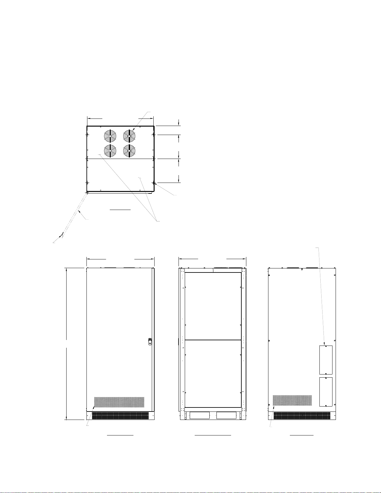
Figure 1 – Outline Drawing................................................................................................... 1
Figure 2 - Pallet Mounting Hardware.................................................................................... 4
Figure 3 - Cabinet to Cabinet Mounting Hole Locations....................................................... 5
Figure 4 - Inside Front View of Transformer Cabinet............................................................ 7
Figure 5 - Cabinet Top Conduit Locations............................................................................ 7
Figure 6 - Options Control Board Assembly....................................................................... 10
Figure 7 - Customer Low Voltage Connection Terminal Block........................................... 11
Figure 8 - Circuit Breaker Sequence Label ........................................................................ 17

Page | 1
1 INTRODUCTION
1.1 Overview
The Transformer Cabinet for 65 kVA, 80 kVA, 100 kVA, and 125 kVA is a steel cabinet that
can either attach to the left side of the UPS cabinet or remain free standing. The purpose of
the Transformer Cabinet is to allow operation of a UPS 480 V in/out with 208 V input and/or
output and/or provide an output neutral when an input neutral is desired but not available.
See Figure 1 for the outline drawing of the Transformer Cabinet.
Figure 1 – Outline Drawing
FRONT VIEW RIGHT SIDE VIEW REAR VIEW
11.85 [301.0]
11.85 [301.0]
32.75 [831.8]
(6) Ø.41 [Ø10.3]
MOUNTING HOLES
ON BOTTOM FEET
33.50 [850.8]
4.46 [113.2]
TOP VIEW .11 [2.8] THICK
33.35 [847.0]
75.00 [1905.0]
HINGED FRONT DOOR
DOOR LATCH REQUIRES PHILLIPS
SCREWDRIVER TO OPEN
EXHAUST FANS
REMOVABLE TOP COVERS
.08 [2.0] THICK
VENTILATION HOLES
VENTILATION HOLES
CONDUIT LANDING PLATES
.06 [1.6] THICK HERE
AND ON BOTTOM FLOOR

Page | 2
1.2 Applicability
When present, the input transformer is always a 208 V primary to 480 V secondary
autotransformer with a circuit breaker between the transformer and the UPS. If input is wye
configured, the input neutral connects to the autotransformer and the ground bond in the
UPS is removed. If input is delta configured, the input neutral terminal is not used.
An autotransformer with 208 V primary to 480 V/277 V secondary is used for the
following:
o208 V wye to 208 V/120 V wye
o208 V wye to 480 V/277 V wye
o208 V delta to 208 V delta
o208 V delta to 480 V delta
The output transformer always has a breaker between the UPS output and the transformer
primary. There are three configurations of three phase output transformers available for use
in the Transformer Cabinet:
An autotransformer with 480 V primary to 280 V/120 V secondary is used for the
following:
o208 V wye to 208 V/120 V wye
o480 V wye to 208 V/120 V wye
o208 V delta to 208 V delta
o480 V delta to 208 V delta
An isolation transformer with 480 V primary to 208 V/120 V secondary is used for the
following:
o208 V delta to 208 V/120 V wye
o480 V delta to 208 V/120 V wye
An isolation transformer with 480 V primary to 480 V/277 V secondary is used for the
following:
o480 V delta to 480 V/277 V wye

Page | 3
2. CABINET SETUP
This SECTION describes:
Equipment inspection
Floor loading and clearances
Removing and replacing the cabinet panels
Unloading the cabinet(s)
Attaching the cabinet to the UPS
If a Maintenance Bypass Switch (MBS) is installed, the site where the equipment is located
must be such that the required control connections between the cabinet and the UPS are
no greater than 30 feet or 10 meters in length.
2.1 Inspecting the Equipment
If any equipment has been damaged during shipment, keep the shipping and packing
materials for the carrier or place of purchase and file a claim for shipping damage. If you
discover damage after acceptance, file a claim for concealed damage.
To file a claim for shipping damage or concealed damage: 1) File with the carrier within 15
days of receipt of the equipment, 2) Send a copy of the damage claim within 15 days to
your service representative.
2.2 Floor Loading
When planning the installation, consider the battery cabinet weight for floor loading. The
strength of the installation surface must be adequate for point and distributed loading. The
approximate weights are shown in the following table.
Table 2 - Model Floor Loadings
STANDARD MODEL FLOOR LOADING
MODEL MAXIMUM WEIGHT POINT LOADING
w/ autotransformer 1130 lbs (513 kg) 8.6 lb/in2(0.6 kg/cm2)
w/ (2) autotransformers 1760 lbs (798 kg) 13.5 lb/in2(0.9 kg/cm2)
w/ auto & isolation transformers 2100 lbs (952 kg) 16 lb/in2(1.1 kg/cm2)
w/ isolation transformer 1470 lbs (667 kg) 11.2 lb/in2(0.8 kg/cm2)
2.3 Clearances
The following clearances are recommended for the Transformer Cabinet:
From Front of Cabinet 36” (91.4 cm) working space

Page | 4
2.4 Unloading the Cabinet(s)
The following tools are required for unloading the cabinet(s):
Wrenches for 3/8” lag bolts.
Forklift or pallet jack
The cabinets are heavy (see Table 2). Unloading the cabinets requires at least two
people to safely remove the cabinets from the pallet.
To remove the Transformer Cabinet from the ship pallet:
1. Make sure the forklift is rated for the cabinet weight.
2. Make sure the path traveled has sufficient support for the combined weight of the
forklift and the cabinet.
3. Make sure forks are at maximum separation.
4. Use a very strong ratchet strap (or similar device) of sufficient strength to tie the
upper part of the cabinet to the forklift tower before moving.
5. Keep people out of the fall zone. If the cabinet topples over, stand clear
6. With a Phillip’s screwdriver, remove the two kick panels. These will be remounted
when the cabinet is in place.
7. Remove all banding, wrapping and foam protection.
8. Remove the six 3/8” lag bolts securing the cabinet to the pallet. See Figure 2.
Figure 2 - Pallet Mounting Hardware
9. Lift the cabinet with a forklift one to two inches (1”-2” [2.5-5cm]) above the pallet.
10. Slide the pallet completely away from the raised cabinet.
11. Carefully move the cabinet to the desired location and slowly lower the cabinet to the
floor or other appropriate flat surface.
12. Remount the two kick panels.
WARNING

Page | 5
2.5 Attaching the Cabinet to the UPS
The Transformer Cabinet was constructed so that it can be mounted to the side of the UPS
cabinet if desired. To attach the Transformer Cabinet to the UPS Cabinet:
1. Remove left side panel of UPS and save hardware.
2. Butt right side of Transformer Cabinet up against the left side of the UPS.
3. Bolt the cabinets together at (6) locations with the supplied 5/16 hardware through
the slots noted as "A" in Figure 3.
4. Mount left side panel of UPS on the left side of the Transformer Cabinet using the
hardware from the UPS.
Figure 3 - Cabinet to Cabinet Mounting Hole Locations
2.6 Free-Standing Cabinet
The Transformer Cabinet can be used as a free-standing cabinet, but side panels must be
ordered separately and attached to both sides of the cabinet.
RIGHT SIDE VIEW
AA
AA
AA

Page | 6
3. ELECTRICAL INSTALLATION
3.1 Overview
Each of the pieces of equipment covered by this manual has four sets of power
connections:
1. Input from the power source, typically, from the electric utility.
2. Power routed to the input of the UPS.
3. Power from the output of the UPS.
4. Power to the load
There are four control connections between the Transformer Cabinet and the UPS that
must be made. The required control connections (MBS arrangement only) are described
later in this section.
Only qualified service personnel (such as a licensed electrician) should perform
the installation and initial startup. There is a risk of electrical shock.
3.2 Wiring Preparation
1. Verify that the equipment is the proper type. While the Transformer Cabinet can
come in a variety of configurations, the UPS must be properly configured (refer to
the UPS manual).
2. Plan the location of conduits. Conduit landing plates are provided at the top, rear,
and bottom of the cabinet. As noted, there are four sets of power connections. If the
MBS arrangement is included, one set of control connections will also exist. The low
voltage control connection must be routed through the top front cover of the cabinet,
seven (7) inches (178 mm) minimum from the power wiring to ensure physical
separation between them and the power wiring. The power wiring may enter the
cabinet through the top rear cover, the rear or bottom plates. See Figure 5.
3. All wiring is to be in compliance with all applicable codes.
4. Verify that the source circuit capability is in compliance with the requirements shown
in Table 6.
5. Select wire size in compliance with Table 6.
WARNING

Page | 7
Figure 4 - Inside Front View of Transformer Cabinet
Figure 5 - Cabinet Top Conduit Locations
FRONT VIEW
FRONT DOOR AND KICK PANEL REMOVED
TYPEAND RATINGOFFUSE.
REPLACEON LY WITHSAME
CAUTION!
NCBA FROM UPS OUTPUT
NCBA TO UPS INPUT
DS1
J201
J202
J203
J204
J205
J206
TB9
TB8
TB10 TB11
TB1
TB2 TB3 TB4TB5 TB6
TB7
OTHT
1
1
1
1
1
D19
123
CONDUIT LANDING PLATES
.06 [1.6] THICK ON FLOOR
AND REAR COVER
MAINTENANCE BYPASS OPTION
LOW VOLTAGE CONNECTIONS
NOTICE
FORSUPPLY CONNECTIONS,
USEWIRESSUITABLEFORAT
LEAST90°C
FORUSEINACONTROLLEDENVIRONMENT.
REFERTOHANDBOOKFORENVIRONMENTAL
CONDITIONS.
ATTENTION:
Pourutilisationen atmosphèrecontrolée.
Consu lte r la not ice tec hnique pour l es
conditionsdumilieu.
NCBA OUTPUT TO LOAD NCBA UTILITYINPUT
POWER CONNECTIONS
TO UPS
POWER CONNECTIONS
TO UTILITY AND LOAD
CIRCUIT BREAKERS
OPTIONS CONTROL
PC BOARD ASSEMBLY
TOP VIEW
EXHAUST FANS
.86 [21.8] TYP.
6.70 [170.3]
14.72 [374.0]
4.00 [101.6]
6.25 [158.8]
HIGH VOLTAGE POWER WIRING
CONDUIT IN THIS AREA
LOW VOLTAGE CONTROL
WIRING CONDUIT IN THIS AREA
7.00 [177.8] TYP.
NO WIRING CONDUITS
IN THIS AREA
.84 [21.4] TYP.

Page | 8
3.3 Wiring Installation
1. Switch off utility power to the distribution point where the UPS will be connected.
Be absolutely sure that there are no hazardous voltages present. Use appropriate
procedures to assure safety.
2. Remove as many panels as needed for adequate access for wiring the cabinet.
Open the front door of the Transformer Cabinet.
3. Connect wires from the "TO UPS INPUT" terminal block to the input terminals in
the UPS. (Refer to the UPS manual). The wire must be in compliance with Table
6 and the terminals must be torqued in compliance with Table 7. Make sure that
phase A connects to phase A and so on.
4. Connect wires from the "FROM UPS OUTPUT" terminal block to the output
terminals in the UPS. (Refer to the UPS manual). The wire must be in compliance
with Table 6 and the terminals must be torqued in compliance with Table 7. Make
sure that phase A connects to phase A and so on.
5. Connect wires from the "OUTPUT TO LOAD" terminal block to the load. The load
may be an external distribution panel, etc. If neutral is not needed by the load,
then it does not need to be supplied. The wire must be in compliance with Table 6
and the terminals must be torqued in compliance with Table 7. Make sure that
phase A connects to phase A and so on.
6. Verify that the input power source is not powered. Connect wires from the
"UTILITY INPUT" terminal block to the input source power from the building
distribution. The wire must be in compliance with Table 6 and the terminals must
be torqued in compliance with Table 7. Make sure that phase A connects to
phase A and so on. The source needs to have A-B-C phase sequence. If not,
exchange two of the phase connections to correct this.
7. MBS Arrangement Only: A set of control connections must be installed from the
"CUSTOMER LOW VOLTAGE CONNECTION TERMINAL BLOCK" to the
Remote Commands and Alarm Connections in the front of the UPS cabinet.
These control wires must be physically separated from any power wires. The
length of the control wires is limited to 30 feet or 10 meters. See Section 3.4
Control Connections (MBS Arrangement Only) for wiring details.
8. Check all work. Replace the panels that were removed for access.

Page | 9
3.4 Control Connections (MBS Arrangement Only)
Four control connections must be made between the Transformer Cabinet with MBS
arrangement and the UPS in order to provide backfeed protection, a required safety feature.
There is also a provision to provide Remote Emergency Power Off (REPO). REPO causes
the output breaker to trip, thereby removing power from the load. If the bypass path is
active, then REPO trips the bypass breaker, removing power from the load.
The wiring to these low voltage (“ELV”) connections must be kept separated from the
higher voltage wiring. Refer to Figure 7 regarding the Low Voltage Terminal Block and to
the UPS manual that shows the connection point in the UPS.
3.4.1 Connections Between the Maintenance Bypass Switch and the UPS (MBS Arrangement
Only)
Since these wires affect the operation of the UPS, they should be protected. Running them
in conduit is recommended. It is also recommended that the wires are shielded twisted
pairs. Alpha 6010C is a shielded cable with three twisted pairs and is available from a
number of sources in various spool lengths.
Two pairs are required:
Pair 1 -- First wire from terminal 3 of the Low Voltage Connection Terminal Block (LVTB) of
the Transformer Cabinet with MBS arrangement to terminal 11 of the Remote Commands
and Alarms Connections on the UPS (RCA-UPS). Second wire from terminal 4 of LVTB to
terminal 12 of RCA-UPS.
Pair 2 – First wire from terminal 10 of LVTB to terminal 1 of RCA-UPS. Second wire from
terminal 11 of LVTB to terminal 2 of RCA-UPS.
Figure 7 is an electrical wiring schematic summarizing the connections to the Low Voltage
Connection Terminal Block.
The REPO switch connections are also shown. Please note that typically only one of the
REPO switch contacts is connected, depending on user preference, but both are shown to
illustrate the wiring. The normally open switch connects across terminals 5 and 6 while the
normally closed switch connects across terminals 8 and 9. Terminal 7 has a limited
amount of unregulated dc power available to power an LED lamp to permit the use of a
lighted switch for REPO. Contact Dual-Lite for details if you desire to use this feature. See
Section 3.4.3 Switch Settings (MBS Arrangement Only) to properly configured the
Options Control Board in the Transformer Cabinet for the normally closed REPO switch to
work.
3.4.2 Terminal Strip Torque Requirements (MBS Arrangement Only)
The terminals on the Customer Low Voltage Connection Terminal Block must be torqued to
5.3 to 7.0 inch-lbs. The terminals on the Control Connections (on the UPS) must be torqued
to 4.4 inch-lbs.

Page | 10
3.4.3 Switch Settings (MBS Arrangement Only)
Switch "S2" on the Options Control Board (refer to Figure 6) is a four position "DIP" switch
that has four small rocker switches. Pushing on the top half of each switch section closes
the switch and turns it ON, pushing on the lower half turns the switch OFF. There are
labels on the board to help identify the switch section.
The first section "PLT" enables "Power Loss Trip" (or Manual Restart), and should be OFF
unless you want the Bypass and Inverter Output Breakers to trip on loss of power.
The second section "NCR" enables the Normally Closed REPO input and should be OFF
unless there is a normally closed REPO switch connected.
The third section "OTT" is not implemented and should be turned OFF to avoid confusion.
The fourth section is not used and should be turned OFF to avoid confusion.
Figure 6 - Options Control Board Assembly

Page | 11
Figure 7 - Customer Low Voltage Connection Terminal Block
1413121143215678109
REMOTE COMMANDS AND ALARMS CONNECTIONS
ON FRONT OF UPS BEHIND DOOR
REPO OPTION
NORMALLY OPEN
NORMALLY CLOSED
BYPASS
FAULT BATT.
ON BATT.
LOW EPO
INV.
OFF
SHUNT
GND
IN1
RL1
RL2
RL3
CUSTOMER LOW VOLTAGE CONNECTION TERMINAL BLOCK
(MAINTENANCE BYPASS SWITCH OPTION ONLY)
1234567891011
USE TWISTED
SHIELDED
PAIR WIRE

Page | 12
4. BACKFEED PROTECTION (MBS ARRANGEMENT ONLY)
In some of the possible combinations of switch positions for the MBS, the output of the
UPS could be connected to the input to the system. If the UPS is in Normal mode (the load
is being supplied power from the inverter), this could cause damage to the UPS. Further, if
the input to the system is not powered, the inverter could run on battery and supply voltage
to the input of the system. Service personnel working on the line feeding the input to the
system (or the line feeding that line, etc.) could be subjected to hazardous conditions.
Imagine an electrician opening the supply breaker feeding the MBS and expecting that line
to be safe to work on. A requirement for UPS design is that backfeed must be prevented.
Since the Transformer Cabinet with MBS arrangement is external to the UPS, the UPS
cannot provide backfeed protection without receiving information concerning the position of
the switches of the MBS. An additional requirement is that backfeed protection be provided
with the failure of any one component. That means that the protection must have
redundancy in the method.
The redundant methods implemented in the MBS are as follows:
1. If the UPS Output Breaker (Breaker #3) and the Bypass Breaker (Breaker #2) are
both closed, the UPS is commanded to go to Bypass mode, no matter what. If the
UPS was operating on battery due to an input source failure, the load will lose power,
but it will be impossible for the UPS to cause backfeed. This method requires a
signal from the MBS control to the UPS control via a pair of wires.
2. Unless the UPS is On Bypass OR the UPS Output Breaker (Breaker #3) is open, the
trip mechanism of the Bypass Breaker (Breaker #2) will be activated, preventing it
from closing. This requires a signal from the UPS control to the MBS control via a
pair of wires.
As is explained in Section 5. Operation (MBS Arrangement Only), the proper procedure
for putting the MBS into the Bypassed mode requires that the user first put the UPS in
"Manual" Bypass Mode. Thus the signal that the UPS is On Bypass will be present and the
Bypass Breaker in the MBS can be closed. Further, closing the Bypass Breaker will assert
the command to the UPS to go to bypass, but this will have no effect as the UPS is already
in bypass. That is, if the user follows the correct procedures for operating the MBS, these
backfeed prevention schemes will be completely transparent.
4.1 Remote EPO (Emergency Power Off) (MBS Arrangement Only)
Some applications (notably, data centers) require that there is a provision to remotely shut
down power to the equipment powered by the UPS. Typically, this "remote" control is a red
button switch located next to the exit and wired to the UPS. The Transformer Cabinet with
MBS arrangement is equipped with a Remote EPO input that causes both the Bypass
Breaker (Breaker #2) and the UPS Output Breaker (Breaker #3) to trip when a REPO
switch activation is sensed. This way, power is interrupted regardless of which breaker
was actually supplying current to the load. It may be desirable to also shut down the UPS
upon activation of the EPO function. This requires a separate switch contact (NC) wired in
accordance with the restrictions in the UPS manual.
Note that the UPS has a front panel "EPO" switch. Pressing this switch will cause the UPS
to shut off immediately, but its action is only local. That is, it affects the UPS, but there is
no way for this switch to have a direct operating effect on the Transformer Cabinet with

Page | 13
MBS arrangement. (There are some indirect possibilities. For example, stopping the UPS
by pressing the EPO could cause the On Bypass signal from the UPS to the Transformer
Cabinet with MBS arrangement to change, tripping the Bypass Breaker if the UPS Output
Breaker is also closed. These indirect actions will not affect system operation if the system
is operated according to the procedures in Section 5. Operation (MBS Arrangement
Only).)
Some users prefer to use a normally open switch in the REPO system; others prefer a
normally closed switch. Inputs for both types of switches are provided in the Transformer
Cabinet with MBS arrangement, but the normally closed function has to be enabled by
operating a small rocker switch on the Options Control Board. This is to avoid the problem
of not being able to operate the system if the normally closed circuit is missing, as when the
user only chooses to use the normally open configuration, or when the user does not
choose to use the REPO system at all.
Historically, REPO systems have caused a lot of confusion due to systems not being
capable of operation due to a false signal from the REPO switch(es). To address this issue,
the Options Control Board has a yellow LED lamp (DS1 in the upper right corner of Figure
6) that indicates that the REPO has been activated. The logic that operates the lamp
latches the indication, so it is possible to determine that the REPO was activated at some
time since power was applied to the system. The latched indication can be reset by
pressing S1 on the Options Control Board.
Some users prefer that power not be restored to the load automatically, if lost, so that they
can manually reapply power to the connected loads using a defined sequence. There is a
rocker switch on the Options Control Board that selects this capability. If the switch is ON
and power is lost (both the utility input power to the cabinet and the power from the UPS),
Breakers #2 and #3 will both trip, assuring that the load cannot be powered without
manually closing one of these breakers. Sometimes this feature is called "Manual Restart".

Page | 14
5. OPERATION (MBS ARRANGEMENT ONLY)
Refer to the User's Manual for the UPS for instructions on operating the UPS part of the
system. If the UPS is part of a parallel system, special operating instructions apply.
The purpose of the Maintenance Bypass Switch (MBS) is to facilitate servicing the UPS
without removing power from the load. The main functional components of the MBS are
three circuit breakers that are used as disconnect switches. We will designate them “BKR1”,
“BKR2”, and “BKR3”, but they are labeled “1”, “2”, and “3” above the breaker handles on
the front inner cover of the cabinet. The breakers each have three positions: off (down), on
(up), and tripped (in between off and on). To turn on a tripped breaker, reset the breaker
by pushing the handle down to the off position, and then raise it to the on position. If a
breaker will not reset or trips as being turned on, the backfeed prevention interlock is active
and the proper conditions (as described below) will have to be present before the breaker
can be operated. When closed, BKR1 supplies power from the supply (utility) to the
bypass input of the UPS. For single input UPS configurations, it also supplies power to the
rectifier input. When closed, BKR3 connects the output of the UPS to the load. When
closed, BKR2 bypasses the path through BKR1, the UPS, and BKR3 and connects the
supply directly to the load. BKR2 and BKR3 must never be closed at the same time unless
the UPS is in bypass mode. It does not matter which type of bypass, but bypass via
SWMB is the simplest to engage. There are signals that support an interlock function to
prevent BKR2 from being closed unless BKR3 is open or the UPS is in bypass mode. For
the UPS to be able to issue this signal, the UPS controls must be powered. Always
observe proper switching sequence to avoid loss of power to the load. Common switching
operations are also described, below. There are also some problem scenarios listed.
The three switches (Breaker 1, Breaker 2, and Breaker 3) have eight possible combinations
or "States". Table 3 lists all of the possible states. Note that one possibility (Breaker 1
open, Breaker 2 and Breaker 3 closed) is forbidden as unexpected system behavior could
result, including loss of power to the load. The Overlap State is a transient state. It is the
"make" before the "break". Time spent in this state should be kept to a minimum as
external events could lead to tripping Breaker 2, possibly interrupting power to the load.
Also, please note that the UPS does not condition the power to the load while in bypass
and that battery back-up is not available while in bypass.
To avoid damage to the UPS and to avoid interrupting power to the load, the procedures
listed in Table 4 must be used to change from one state to another. The MBS is equipped
with a label (see Figure 8) that describes the breaker sequences for two common
operations. The "To place load on maintenance bypass" sequence describes going from
Normal State to Overlap to UPS Unloaded to Maintenance. The "To place load on UPS"
sequence describes going from Maintenance State to UPS Unloaded to Overlap to Normal.
Table of contents