Properties of standard variables
Chapter 6 TECHNICAL BULLETIN
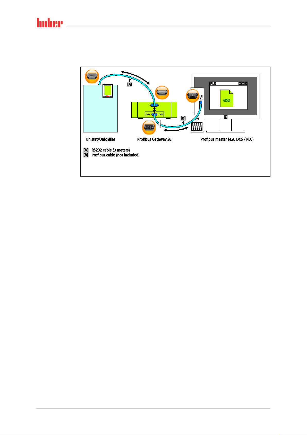
V1.2.0en/05.02.16 Liability for errors and misprints excluded. Profibus® Gateway SE
6Properties of standard variables
6.1 “vSP” – Setpoint, temperature controller
The setpoint is used by the temperature controller. With internal regulation, the setpoint applies for
the internal temperature, with process regulation it applies for the process temperature.
Please note: The setpoint specification can be overwritten by other setpoint indicators (e.g. temper-
ature control program, analog 4…20 mA interface, …).
6.2 “vTI” – Internal temperature
From the point of view of the temperature control device, the current temperature of the thermal
fluid which is flowing to the application. The internal temperature is sometimes also called the flow,
jacket or bath temperature.
6.3 “vpP” – Pump pressure (absolute)
Absolute pump pressure at the pressure sensor in the thermal fluid circuit of the thermostat (only if
there is a pressure sensor).
6.4 “vError” – Error report
The number of the error report that appeared first.
If 0 is returned, no error has occurred and the device is ready for use; otherwise, the nature of the
error can be determined by the number.
6.5 “vWarn” – Warning message
The number of the most recent warning message to appear.
The thermostat may possibly require your attention if a number that is not 0 is returned. If 0 is re-
turned, no new warning has been issued, otherwise the nature of the warning can be determined by
the number. If the warning was requested, 0 is returned at the next inquiry again unless a new
warning has been issued.
6.6 “vTE” – Process temperature (Lemosa)
The current process temperature is returned.
Strictly speaking, the measured value of the Pt100 sensor which is connected to the LEMOSA con-
nector is returned. Typically the processor sensor is connected here.
If no sensor is connected, the value -151 °C is returned.