Huber Piccolo 280 OLE User manual

Piccolo


OPERATION MANUAL
Piccolo


OPERATION MANUAL
V1.1.0en/31.01.22//1.0.0 Piccolo
5
Piccolo
OLÉ
This operation manual is a translation of the original operation manual.
VALID FOR:
Piccolo 280 OLÉ

OPERATION MANUAL
Piccolo V1.1.0en/31.01.22//1.0.0
6
The control panel:
Displays and keys

OPERATION MANUAL
V1.1.0en/31.01.22//1.0.0 Piccolo
7
Table of contents
V1.1.0en/31.01.22//1.0.0
1Introduction 12
1.1 Identification / symbols in the operation manual ......................................... 12
1.2 Information on the EU Declaration of Conformity......................................... 12
1.3 Safety .......................................................................................................... 12
1.3.1 Symbols used for Safety Instructions..............................................................12
1.3.2 Representation of safety identifiers on the temperature control unit...........13
1.3.3 Proper operation.............................................................................................13
1.3.4 Reasonably foreseeable misuse......................................................................14
1.4 Responsible bodies and operators – Obligations and requirements............... 15
1.4.1 Obligations of the responsible body...............................................................15
1.4.1.1 Proper disposal of resources and consumables .........................................15
1.4.2 Requirements for operators ...........................................................................16
1.4.3 Obligations of the operators...........................................................................16
1.5 General information..................................................................................... 16
1.5.1 Description of workstation .............................................................................16
1.5.2 Safety devices to DIN 12876 ...........................................................................16
1.5.3 Further protective devices ..............................................................................17
1.5.3.1 Power interruption.....................................................................................17
1.5.3.2 Overheat protection...................................................................................17
2Commissioning 18
2.1 In-plant transport......................................................................................... 18
2.1.1 Lifting and transporting the temperature control unit...................................18
2.1.1.1 Temperature control unit with lifting eyes ................................................18
2.1.1.2 Temperature control unit without lifting eyes...........................................19
2.1.2 Mounting/removing leveling feet...................................................................19
2.1.3 Positioning the temperature control unit.......................................................20
2.1.3.1 Temperature control unit with casters ......................................................20
2.1.3.2 Temperature control unit without casters.................................................20
2.2 Unpacking.................................................................................................... 20
2.3 Ambient conditions...................................................................................... 20
2.3.1 EMC-specific notes..........................................................................................22
2.4 Installation conditions.................................................................................. 22
2.5 Recommended temperature control hoses................................................... 22
2.6 Preparations for operation........................................................................... 23
2.6.1 Unscrewing/activating the leveling feet (if any) .............................................23
2.6.2 Installing collecting container .........................................................................23
2.6.3 Connecting the functional earth.....................................................................24
2.7 Connecting externally closed application...................................................... 24
2.7.1 Connecting an externally closed application ..................................................24
2.8 Connecting to the power supply................................................................... 24
2.8.1 Connection using socket with protective earth (PE).......................................25
3Function description 26
3.1 Function description of the temperature control unit ................................... 26
3.1.1 General functions............................................................................................26
3.1.2 Other functions...............................................................................................26

OPERATION MANUAL
Piccolo V1.1.0en/31.01.22//1.0.0
8
3.2 Information on the thermal fluids ................................................................ 26
3.3 To be noted when planning the test ............................................................. 27
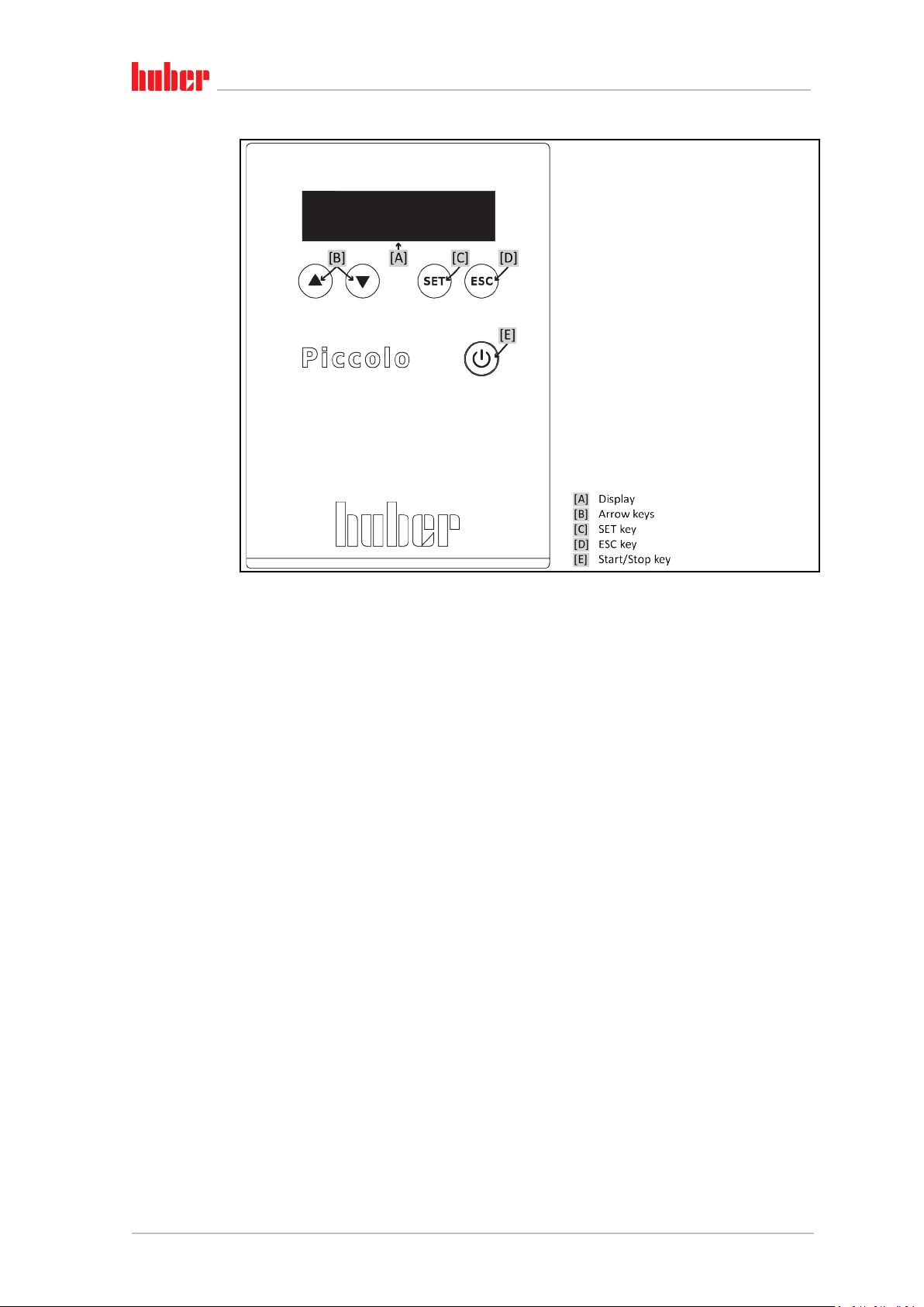
3.4 Display and control instruments................................................................... 28
3.4.1 Display.............................................................................................................28
3.4.2 Control instruments........................................................................................29
3.4.2.1 Arrow keys..................................................................................................29
3.4.2.2 SET key........................................................................................................29
3.4.2.3 ESC key .......................................................................................................30
3.4.2.4 Start/Stop key.............................................................................................30
3.4.3 Adjusting settings............................................................................................30
3.5 Menu function ............................................................................................. 31
3.6 Functional examples .................................................................................... 32
3.6.1 Selecting a language .......................................................................................32
3.6.2 Setting the setpoint ........................................................................................32
3.6.3 Changing the Auto-Start function ...................................................................32
4Setup mode 33
4.1 Setup mode ................................................................................................. 33
4.1.1 Turning on the temperature control unit .......................................................33
4.1.2 Turning off the temperature control unit.......................................................33
4.2 Filling, venting and draining ......................................................................... 33
4.2.1 Cooling circuit .................................................................................................34
4.2.1.1 Filling the cooling circuit.............................................................................34
4.2.1.2 Draining the cooling circuit ........................................................................34
4.2.2 Externally closed application ..........................................................................35
4.2.2.1 Filling and venting externally closed application........................................35
4.2.2.2 Draining externally closed applications......................................................36
5Normal operation 37
5.1 Automatic operation.................................................................................... 37
5.1.1 Temperature control.......................................................................................37
5.1.1.1 Starting the temperature control process..................................................37
5.1.1.2 Ending the temperature control process ...................................................37
6Interfaces and data communication 38
6.1 Interfaces on the temperature control unit................................................... 38
6.1.1 Interfaces at the back .....................................................................................38
6.1.1.1 USB-2.0 interface........................................................................................38
6.1.1.2 RS232 jack...................................................................................................38
6.2 Data communication.................................................................................... 39
6.2.1 LAI commands.................................................................................................39
6.2.1.1 Command “V” (Verify)................................................................................40
6.2.1.2 Command “L” (Limit) ..................................................................................40
6.2.1.3 Command “G” (General) ............................................................................41
6.2.2 PP commands..................................................................................................42
7Service/maintenance 44
7.1 Displays in the event of faults....................................................................... 44
7.2 Electrical fuse............................................................................................... 45
7.3 Maintenance................................................................................................ 45
7.3.1 Function check and visual inspection .............................................................45
7.3.2 Replacing temperature control hoses.............................................................46
7.3.3 Testing overheat protection for functionality.................................................47

OPERATION MANUAL
V1.1.0en/31.01.22//1.0.0 Piccolo
9
7.4 Thermal fluid inspection, replacement and circuit cleaning........................... 48
7.4.1 Thermal fluid inspection .................................................................................48
7.4.2 Thermal fluid replacement .............................................................................48
7.4.2.1 Externally closed application......................................................................48
7.4.3 Rinsing the thermal fluid circuit......................................................................49
7.5 Cleaning the surfaces ................................................................................... 50
7.6 Inspect the mechanical seal.......................................................................... 50
7.7 Plug contacts................................................................................................ 50
7.8 Decontamination/repairs ............................................................................. 50
8Shutting down 52
8.1 Safety instructions and basic principles ........................................................ 52
8.2 Switch-off .................................................................................................... 52
8.3 Draining the temperature control unit.......................................................... 53
8.4 Uninstalling an external application ............................................................. 53
8.5 Deinstalling the collecting container............................................................. 53
8.6 Draining the cooling circuit........................................................................... 53
8.7 Packing ........................................................................................................ 53
8.8 Shipping....................................................................................................... 53
8.9 Disposal ....................................................................................................... 54
8.10 Contact data ................................................................................................ 54
8.10.1 Telephone number: Customer Support ..........................................................54
8.10.2 Telephone number: Sales ...............................................................................54
8.10.3 Email address: Customer Support...................................................................54
8.11 Certificate of Compliance ............................................................................. 55
9Annex 56

OPERATION MANUAL
Piccolo V1.1.0en/31.01.22//1.0.0
10

OPERATION MANUAL
V1.1.0en/31.01.22//1.0.0 Piccolo
11
Foreword
Dear Customer,
Thank you for choosing a temperature control unit from Peter Huber Kältemaschinenbau SE. You
have made a good choice. Thank you for your trust.
Please read the operation manual carefully before putting the unit into operation. Strictly follow all
notes and safety instructions.
Follow the operation manual with regard to transport, start-up, operation, maintenance, repair,
storage and disposal of the temperature control unit.
We fully warrant the temperature control unit for the specified intended operation.
The models listed on page 5 are referred to in this operation manual as temperature control units
and Peter Huber Kältemaschinenbau SE as Huber company or Huber.
Liability for errors and misprints excluded.
The following trademarks and the Huber logo are registered trademarks of Peter Huber Kältemaschinenbau SE in
Germany and/or other countries worldwide: BFT®, CC®, Chili®, Com.G@te®, Compatible Control®, CoolNet®,
DC®, E-grade®, Grande Fleur®, Huber Piccolo®, KISS®, Minichiller®, Ministat®, MP®, MPC®, Peter Huber Mini-
chiller®, Petite Fleur®, Pilot ONE®, RotaCool®, Rotostat®, SpyControl®, SpyLight®, Tango®, TC®, UC®, Unical®,
Unichiller®, Unimotive®, Unipump®, Unistat®, Unistat Tango®, Variostat®. The following trademarks are regis-
tered in Germany to DWS Synthesetechnik: DW-Therm®, DW-Therm HT®. The following trademark is a registered
trademark of BASF SE: Glysantin®.

Introduction
OPERATION MANUAL Chapter 1
Piccolo V1.1.0en/31.01.22//1.0.0
12
1Introduction
1.1 Identification / symbols in the operation manual
The following identifications and symbols are used in the texts and illustrations.
Identification / symbol Description
→Reference to information / procedure.
»TEXT« Reference to a chapter in the operation manual. In the digital version, the text
is clickable.
>TEXT< [NUMBER] Reference to the wiring diagram in the annex. The designation and the search
digit are specified.
>TEXT< [LETTER] Reference to a drawing in the same paragraph. The designation and the
search digit are specified.
▪List, first level
‒List, second level
1.2 Information on the EU Declaration of Conformity
The equipment complies with the basic health and safety requirements of the European Directives
listed below:
▪Machinery Directive
▪Low Voltage Directive
▪EMC Directive
1.3 Safety
1.3.1 Symbols used for Safety Instructions
Safety instructions are marked by the below combinations of pictograms and signal words. The
signal word describes the classification of the residual risk when disregarding the operation manual.
Denotes an immediate hazardous situation that will result in death or serious injuries.
Denotes a general hazardous situation that may result in death or serious injuries.
Denotes a hazardous situation that can result in injury.
Denotes a situation that can result in property material damage.
Denotes important notes and usable hints.
Overview

Introduction
Chapter 1 OPERATION MANUAL
V1.1.0en/31.01.22//1.0.0 Piccolo
13
Notes in conjunction with Ex px cabinets.
The safety information in this operation manual is designed to protect the operating company, the
operator and the equipment from damage. First inform yourself about any residual risks due to
misuse before you start an operation.
1.3.2 Representation of safety identifiers on the temperature control unit
The following pictograms are used as safety identifiers. The table gives an overview of the safety
identifiers used here.
Identifier Description
Mandatory sign
- Observe the instructions
Warning sign
- General warning sign
- Observe the instructions
- Warning of electrical voltage
- Warning of hot surface
- Warning of flammable substances
1.3.3 Proper operation
Operating the temperature control unit in a potentially explosive area
DEATH THROUGH EXPLOSION
Do NOT install or start up the temperature control unit within an ATEX zone.
Safety information and
procedure
Overview

Introduction
OPERATION MANUAL Chapter 1
Piccolo V1.1.0en/31.01.22//1.0.0
14
Improper use
SERIOUS INJURY AND PROPERTY DAMAGE
Store the operation manual where it is easy to access in close proximity to the temperature
control unit.
Only adequately qualified operators may work with the temperature control unit.
Operators must be trained before handling the temperature control unit.
Check that the operators have read and understood the operation manual.
Define precise responsibilities of the operators.
Personal protective equipment must be provided to the operators.
Be sure to follow the responsible body’s safety rules to protect life and limb and to limit dam-
ages!
Modifications to the temperature control unit by third-parties
DAMAGE TO THE TEMPERATURE CONTROL UNIT
Do not allow third parties to make technical modifications to the temperature control unit.
The EU declaration of conformity becomes invalid if any modifications are made to the tem-
perature control unit without the approval of Huber.
Only specialists trained by Huber may carry out modifications, repairs or maintenance work.
The following must be observed without fail:
Only use the temperature control unit in a fault-free condition!
Have the start-up and repairs carried out by specialists only!
Do not ignore, bypass, dismantle or disconnect any safety devices!
The temperature control unit must not be used for any purposes other than temperature control in
accordance with the operation manual.
The temperature control unit is made for industrial use. The temperature control unit is used to
maintain the temperature of applications, such as glass or metal reactors or other expedient items
in laboratories and industry. Flow-through coolers and calibration baths must be used only in com-
bination with Huber temperature control units. Only use thermal fluids suitable for the overall sys-
tem. The cooling or heating capacity is provided at the pump connections or - where present - in the
tempering bath. For the technical specification, refer to the datasheet. →From page 56, section
»Annex«. Install, set up and operate the temperature control unit according to the instructions in
this operation manual. Any failure to comply with the operation manual is considered as improper
operation. The temperature control unit was manufactured according to the state of the art and the
recognized safety rules and regulations. Safety devices are installed in your temperature control
unit.
1.3.4 Reasonably foreseeable misuse
Without an Ex px cabinet, the temperature control unit / accessory is NOT protected against ex-
plosion and must NOT be installed or put into operation within an ATEX Zone. When operating the
temperature control unit /accessory in conjunction with an Ex px cabinet, the information in the
annex (Section ATEX operation) must be observed and followed. This annex is only provided for
temperature control units /accessories delivered with an Ex px cabinet. If this annex is missing,
please immediately contact the Customer Support. →Page 54, section »Contact data«.
Use with medical devices (e.g. in Vitro diagnostic procedure) or for direct foodstuff temperature
control is NOT permissible.
The temperature control unit must NOT be used for any purposes other than temperature control in
accordance with the operation manual.
The manufacturer accepts NO liability for damage caused by technical modifications to the temper-
ature control unit, improper handling or use of the temperature control unit if the operation manu-
al is not observed.

Introduction
Chapter 1 OPERATION MANUAL
V1.1.0en/31.01.22//1.0.0 Piccolo
15
1.4 Responsible bodies and operators – Obligations and
requirements
1.4.1 Obligations of the responsible body
The operation manual is to be stored where it is easy to access in close proximity to the temperature
control unit. Only adequately qualified operators (e.g. chemists, CTA, physicists etc.) are permitted
to work with the temperature control unit. Operators must be trained before handling the tempera-
ture control unit. Check that the operators have read and understood the operation manual. Define
precise responsibilities of the operators. Personal protective equipment must be provided to the
operators.
▪The responsible body must install a condensation water / thermal fluid drip tray below the tem-
perature control unit.
▪The use of a drip tray may be prescribed by national legislation for the installation area of the
temperature control unit (incl. accessory). The responsible body must check and apply the na-
tional regulations applicable for it accordingly.
▪The temperature control unit complies with all applicable safety standards.
▪Your system, which uses our temperature control unit, must be equally safe.
▪The responsible body must design the system to ensure it is safe.
▪Huber is not responsible for the safety of your system. The responsible body is responsible for the
safety of the system.
▪Although the temperature control unit provided by Huber meets all the applicable safety stand-
ards, integration into a system may give rise to hazards that are characteristic of the other sys-
tem’s design and beyond the control of Huber.
▪It is the responsibility of the system integrator to ensure that the overall system, into which this
temperature control unit is integrated, is safe.
▪The >Mains isolator< [36] (if present) can be locked in the off position to facilitate safe system
installation and maintenance of the temperature control unit. It is the responsibility of the re-
sponsible body to develop any lock-out/tag-out procedure for the energy source in accordance
with local regulations (e.g. CFR 1910.147 for the US).
1.4.1.1 Proper disposal of resources and consumables
Do comply with all national disposal regulations applicable for you. Contact your local waste man-
agement company for any questions concerning disposal.
Material / Aids Disposal / Cleaning
Packaging material Keep the packaging material for future use (e.g. transport).
Thermal fluid
Please refer to the safety data sheet of the thermal fluid used for information on its
proper disposal.
Use the original thermal fluid container when disposing it.
Filling accessories, e.g.
beaker
Clean the filling accessories for reuse. Make sure that the materials and cleaning
agents used are properly disposed of.
Aids such as towels,
cleaning cloths
Tools used to take up spilled thermal fluid must be disposed of in the same fashion
as the thermal fluid itself.
Tools used for cleaning must be disposed of depending on the cleaning agent used.
Cleaning agents such as
stainless steel cleaning
agents, sensitive-fabrics
detergents
Please refer to the safety data sheet of the cleaning agent used for information on its
proper disposal.
Use the original containers when disposing of large quantities of cleaning agents.
Consumables such as air
filter mats, temperature
control hoses
Please refer to the safety data sheet of the consumables used for information on
their proper disposal.
Overview

Introduction
OPERATION MANUAL Chapter 1
Piccolo V1.1.0en/31.01.22//1.0.0
16
1.4.2 Requirements for operators
Work on the temperature control unit is reserved for appropriately qualified specialists, who have
been assigned and trained by the responsible body to do so. Operators must be at least 18 years old.
Under 18-year olds may operate the temperature control unit only under the supervision of a quali-
fied specialist. The operator is responsible vis-a-vis third-parties in the work area.
1.4.3 Obligations of the operators
Carefully read the operation manual before operating the temperature control unit. Please observe
the safety instructions. When operating the temperature control unit, wear appropriate personal
protective equipment (e.g. safety goggles, protective gloves, non-slip shoes).
1.5 General information
1.5.1 Description of workstation
The workstation is located at the control panel in front of the temperature control unit. The work-
station is determined by the customer's connected peripheries. Accordingly, it must be designed
safe by the responsible body. The workstation design also depends on the applicable requirements
of the German occupational health and safety regulations [BetrSichV] and the risk analysis for the
workstation.
1.5.2 Safety devices to DIN 12876
The rating of your temperature control unit is stated on the data sheet in the appendix.
Classification Temperature
control medium Technical requirements Identification d)
I Non-combustible a) Overheat protection c) NFL
II Combustible b) Adjustable overheat protection FL
III Combustible b) Adjustable overtemperature protection
and additional low-level protection FL
a) Usually water; other fluids only if non-combustible even within the temperature range of an individual fault.
b) The temperature control media must have a fire point of ≥ 65 °C.
c) The overheat protection can, for instance, be realized using a suitable fill level sensor or a suitable temperature
limiter.
d) Optional at the choice of the manufacturer.
Rating of laboratory
thermostats and
laboratory baths
Overview of the tem-
perature thresholds

Introduction
Chapter 1 OPERATION MANUAL
V1.1.0en/31.01.22//1.0.0 Piccolo
17
1.5.3 Further protective devices
Emergency strategy – interrupt the power grid connection!
To determine the type of switch or switch combination your temperature control unit is equipped
with, please refer to the wiring diagram. →From page 56, section »Annex«.
Temperature control units with >Mains isolator< [36] (red/yellow or gray): Turn the >Mains
isolator< [36] to the “0” position.
Temperature control units with >Mains isolator< [36] (red/yellow) and additional >Appliance
switch< [37] (gray): Turn the >Mains isolator< [36] to the “0” position. Then turn the >Appliance
switch< [37] to the “0” position!
Temperature control units with >Mains isolator< [36] (gray) and >Emergency stop switch< [70]
(red/yellow): Press the >Emergency stop switch< [70]. Then turn the >Main switch< [36] to the
“0” position!
Temperature control units with >Mains switch< [37]:Power supply via socket: Disconnect the
temperature control unit from the power supply. Then turn the >Mains isolator< [37] to the “0”
position! Power supply via hard wiring: Disconnect the power grid supply by means of the build-
ing’s circuit breaker. Then turn the >Mains isolator< [37] to the “0” position!
Temperature control units without a switch or inside a protective housing: Connection via sock-
et: Disconnect the temperature control unit from the power supply. Connection via hard wiring:
Disconnect the power grid supply by means of the building’s circuit breaker!
1.5.3.1 Power interruption
Following a power outage (or when switching on the temperature control unit), this function can be
used to determine how the temperature control unit is supposed to respond.
Auto start function switched off
The temperature control is started only by manual input when the temperature control unit is
turned on.
Auto start function switched on
The temperature control unit is set to the same state it was in before the power outage. For exam-
ple, before the power outage: Temperature control is off; after power outage: Temperature control
is off. If temperature control was active during a power outage, the process will automatically con-
tinue after the power outage.
→Page 32, section »Changing the Auto-Start function«.
1.5.3.2 Overheat protection
Your temperature control unit has a built-in overheat protection that is set to a fixed temperature at
the factory. This overheat protection only protects the circulation pump installed in the temperature
control unit. If the overheat protection has tripped: Turn off the temperature control unit and wait
until the components in the temperature control unit have cooled down.

Commissioning
OPERATION MANUAL Chapter 2
Piccolo V1.1.0en/31.01.22//1.0.0
18
2Commissioning
2.1 In-plant transport
Temperature control unit is not transported / moved according to the specifications in this oper-
ation manual
DEATH OR SERIOUS INJURY DUE TO CRUSHING
Always transport / move the temperature control unit according to the specifications in this
operation manual.
Wear personal protective equipment during transport.
Always work with the specified number of persons when moving the temperature control unit
on casters (if any).
If the temperature control unit is equipped with casters and parking brakes: 2 parking brakes are always
freely accessible when moving the temperature control unit. Activate the 2 parking brakes in an emergen-
cy! If only one parking brake is activated on the casters in an emergency: The temperature control unit is
not stopped but rotates around the axis of the caster with the activated parking brake!
Filled temperature control unit is transported
MATERIAL DAMAGE DUE TO OVERFLOWING THERMAL FLUID
Only transport an emptied temperature control unit.
▪If available, use the lugs on the top side of the temperature control unit for transportation.
▪Use an industrial truck for transport.
▪The casters (if present) on the temperature control unit are not suitable for transport. The casters
are symmetrically loaded with 25% of the total mass of the temperature control unit.
▪Remove the packing material (e.g. the palette) only at the place of installation.
▪Protect the temperature control unit from transport damage.
▪Do not transport the temperature control unit alone and without aids.
▪Check the load bearing capacity of the transportation route and the place of installation.
▪The parking brakes at the casters (if any) must be activated and/or the leveling feet (if any) must
be unscrewed/activated before the temperature control unit is put into operation. →Page 23,
section »Unscrewing/activating the leveling feet (if any)«.
2.1.1 Lifting and transporting the temperature control unit
2.1.1.1 Temperature control unit with lifting eyes
The temperature control unit is raised at the lifting eyes without load handling attachments
DAMAGE TO THE TEMPERATURE CONTROL UNIT
Always use load handling attachments when lifting and transporting the temperature control unit.
The lifting eyes are only designed for a load without inclination (0°).
The load handling attachment used must be adequately dimensioned. Take the dimensions and
weight of the temperature control unit into account.
▪Do not lift and transport the temperature control unit at the lifting eyes alone and without aids.
▪Lift and transport the temperature control unit at the lifting eyes only with a crane or an industrial truck.
▪The crane or industrial truck must have a lifting force equal to or greater than the weight of the
temperature control unit. See the data sheet for the weight of the temperature control unit.
→From page 56, section »Annex«.
Example: lifting eyes
(round, angular, and
recessed (left to right))

Commissioning
Chapter 2 OPERATION MANUAL
V1.1.0en/31.01.22//1.0.0 Piccolo
19
▪If the leveling feet have been removed for shipping: Only lower the temperature control unit when all
leveling feet have been installed. →Page 19, section »Mounting/removing leveling feet«.
2.1.1.2 Temperature control unit without lifting eyes
▪Do not lift and transport the temperature control unit alone and without aids.
▪Lift and transport the temperature control unit only with an industrial truck.
▪The industrial truck must have a lifting force equal to or greater than the weight of the tempera-
ture control unit. See the data sheet for the weight of the temperature control unit. →From page
56, section »Annex«.
▪If the leveling feet have been removed for shipping: Only lower the temperature control unit when all
leveling feet have been installed. →Page 19, section »Mounting/removing leveling feet«.
2.1.2 Mounting/removing leveling feet
Only valid if the leveling feet have been removed for shipping.
The temperature control unit is not secured against slipping and/or lowering
DEATH OR SERIOUS INJURY DUE TO CRUSHING
Secure the temperature control unit against slipping and/or lowering before the leveling feet
are mounted.
Do not stand or lie under the temperature control unit for mounting.
The leveling feet were removed for shipping the temperature control unit. Before placing / posi-
tioning the temperature control unit all leveling feet must be mounted. If the temperature control
unit is re-shipped: Remove all leveling feet before packaging.
▪The leveling feet can only be mounted while the temperature control unit is lifted.
▪Secure the temperature control unit against slipping and/or lowering.
▪Do not stand or lie under the temperature control unit while mounting the leveling feet.
▪Do not lower the temperature control unit until all leveling feet have been mounted.
Example: Supporting
points for forklift arms
for free-standing
models from a certain
overall size. For the
exact position please
refer to the wiring
diagram in the annex.
Example: mounting
the leveling feet

Commissioning
OPERATION MANUAL Chapter 2
Piccolo V1.1.0en/31.01.22//1.0.0
20
2.1.3 Positioning the temperature control unit
2.1.3.1 Temperature control unit with casters
▪Do not use the casters for the transportation to the place of installation. →Page 18, section »Lift-
ing and transporting the temperature control unit«.
▪Use the casters only for positioning at the place of installation.
▪Only ever move the temperature control unit on the casters if the surface is level, without gradi-
ent, non-slip and stable.
▪Do not move the temperature control unit alone.
▪At least 2 persons are required to move the temperature control unit on casters. At least 5 per-
sons are required to move the temperature control unit on the casters if the total weight of the
temperature control unit is over 1.5 tons.
▪The parking brakes must be activated at the casters and/or the feet (if present) must be un-
screwed/activated before the temperature control unit is put into operation. →Page 23, section
»Unscrewing/activating the leveling feet (if any)«.
2.1.3.2 Temperature control unit without casters
▪An industrial truck must be used for positioning the temperature control unit.
▪Do not move the temperature control unit alone.
▪At least 2 persons are required to move the temperature control unit.
▪The industrial truck must have a lifting force equal to or greater than the weight of the tempera-
ture control unit. See the data sheet for the weight of the temperature control unit. →From page
56, section »Annex«.
▪The leveling feet (if present) must be unscrewed/activated before the temperature control unit is
put into operation. →Page 23, section »Unscrewing/activating the leveling feet (if any)«.
2.2 Unpacking
Starting up a damaged temperature control unit
DANGER TO LIFE FROM ELECTRIC SHOCK
Do not operate a damaged temperature control unit.
Please contact Customer Support. →Page 54, section »Contact data«.
PROCEDURE
Check for damage to the packaging. Damage can indicate material damage to the temperature
control unit.
Check for any transport damage when unpacking the temperature control unit.
Always contact your forwarding agent regarding the settlement of claims.
Observe the proper disposal of packaging material. →Page 15, section »Proper disposal of
resources and consumables«.
2.3 Ambient conditions
Unsuitable ambient conditions / unsuitable installation
SERIOUS INJURY DUE TO CRUSHING
Comply with all requirements! →Page 20, section »Ambient conditions« and →Page 22,
section »Installation conditions«.
Make sure there is adequate fresh air available at the site for the circulation pump and the com-
pressors. The warm exhaust air must be able to escape upwards unhindered.
Free-standing models
For the connection data, see the data sheet. →From page 56, section »Annex«.
Table of contents
Other Huber Laboratory Equipment manuals