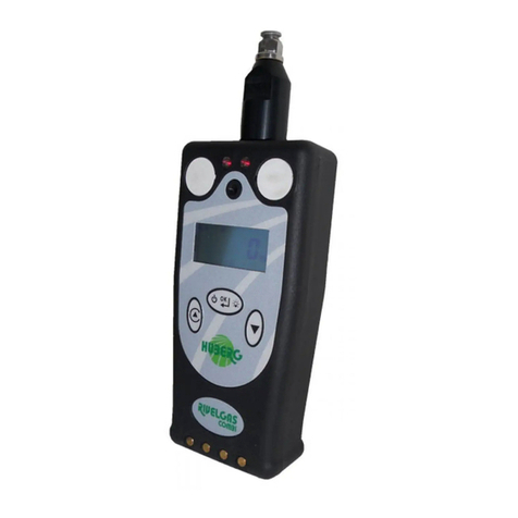
Huberg METREX2 User manual

METREX2
USER MANUAL
VERSION 2.5

Form creation date: 01.04.2008
Document creation date: 13.01.2020
2 / 18
Our products for gas safety
The professional instrument for the
detection and localization of gas leaks
for CH4 e C3H8 with Bluetooth and
GPS.
There is also a version with Ethane
sensor.
Set of probes for all purposes
to use with HUBERG
instruments: carpet probe,
sucker probe,flexible probe,
hand held probe and
extendible probe.
The new portable instrument for gas
leak detection and localization of gas
leaks for CH4 e C3H8 and for toxic gas
(O2, CO, H2S)
Portable instrument for
verifying the calibration and
the flow rate.
Instrument for the personal safety, for
HC (CH4 e C3H8) and toxic gases (O2,
CO, H2S).
Portable instrument for the
detection and localization of
micro gas leaks (CH4 e C3H8)
and for personal safety (O2,
CO, H2S).
Portable instrument for the detection
of methane and propane.
The portable gas
chromatograph for the
measurement and analysis of
odorants in gas distribution
networks.
Explosion-proof vacuum aspiration
pump to drain residual gas from the
ground.
Instrument for the
measurement of THT in
network.
Special vehicles for preventive and systematic gas leak
survey in real-time (selectivity IR methane detection, GPS
on board). System controlled by computer and all the
survey can be connect to the company cartographical
system.

Form creation date: 01.04.2008
Document creation date: 13.01.2020
3 / 18
INDEX
Our products for gas safety........................................................................................................................................ 3
1.0 GENERAL DESCRIPTION ......................................................................................................................................... 5
2.0 KEYBOARD AND CONNECTIONS ............................................................................................................................ 6
3.0 INSTRUMENT PERFORMANCE ............................................................................................................................... 7
3.1 HOW TO SWITCH ON INSTRUMENT .................................................................................................................................... 7
3.2 PPM AND VOL MEASURING RANGES ................................................................................................................................. 8
3.3 LEL MEASURING RANGE .................................................................................................................................................. 8
3.4 ALARM ........................................................................................................................................................................ 9
3.5 DATA REGISTRATION (OPTIONAL) ................................................................................................................................. 10
3.6 AUTO ZEROING ............................................................................................................................................................ 11
3.7 DISPLAY ILLUMINATION ................................................................................................................................................. 11
3.8 RECHARGING OF BATTERIES ............................................................................................................................................ 11
3.9 BATTERY STATUS VISUALIZATION ..................................................................................................................................... 12
4.0 GAS TYPE SELECTION (OPTIONAL) ...................................................................................................................... 13
5.0 PUMP BLOCK ...................................................................................................................................................... 13
6.0 MAINTENANCE AND PERIODICAL CALIBRATION ................................................................................................. 14
7.0 WARRANTY ......................................................................................................................................................... 14
APPENDIX A – SAFE USE OF THE INSTRUMENT ......................................................................................................... 21
Appendix B - Important information for correct disposal of the electric and electronic equipment ............................... 23

Form creation date: 01.04.2008
Document creation date: 13.01.2020
4 / 18
1.0 GENERAL DESCRIPTION
The METREX2 is a digital gas detection instrument which can be used for systematical survey of
natural and town gas networks and for leak detection outside as well as inside of buildings.
Due to its compact design and modest size the METREX2 can be transported easily and the large
LCD-display with the instantaneous reading of the gas concentration measured makes it simple to
work with this device. Furthermore, a selection of various types of probes makes it possible to use
it at points otherwise difficult to reach.
A microprocessor manages all the instrument performances: control of the sensor for the detection
of gas concentrations, the functions of the instrument which can be commanded by keyboard,
management of alarms, registration of data and serial communication for download on PC of
memorized data.
This unit is designed to comply the actual ATEX directive.
METREX2 works with a group of ecological harmless, rechargeable nickel metal hydride batteries
which allow - when fully charged - a working autonomy of at least 8 hours under normal working
conditions and a constant temperature of 20 °C.
Important: Recharging of batteries and I/O connection must be carried out in safe environments.
The METREX2 has three measuring ranges: PPM (part per million), %Vol (volumetric) and the LEL
(Lower Explosion Limit).
The METREX2 has three sensors: one semiconductor sensor, one pellistor pair sensors and one
volumetric thermal conductivity pair sensors.

Form creation date: 01.04.2008
Document creation date: 13.01.2020
5 / 18
2.0 KEYBOARD AND CONNECTIONS
Figure 1
1. Switch OFF button
2. Data recording button
3. Switch ON/OFF acoustic signal button
4. Switch button PPM/VOL/LEL button
5. Auto zeroing button
6. 220 V~ connection LED
7. Battery recharge LED
8. ON/OFF acoustic signal LED
9. Alarm threshold LED
10. VOL scale LED
11. Display
Figure 2
1. Air outlet
2. Quick coupling for probes
3. Buzzer
4. Socket for battery charger/serial port for data download
5. Cover

Form creation date: 01.04.2008
Document creation date: 13.01.2020
6 / 18
3.0 INSTRUMENT PERFORMANCE
3.1 How to switch on instrument
In order to switch on the instrument push, for
at least three seconds, one of the buttons at
the lower part on the right of the keyboard
(fig.1 button (2), (3), (4),(5)). When switched
on, a serial number of the instrument will be
shown on the display (fig.3), followed by an
acoustic signal.
Subsequently the display will show “Px.x”
(software version) and “CAL” (calibration in
progress, fig.4 and fig.5)
fig. 3
fig. 4
fig. 5
The phase of warming up and auto calibration
takes about 1 minutes after switching on the
instrument.
When finished, the device automatically
changes to the PPM scale.
ATTENTION:
Switching on of the instrument must take
place in place free from gas.

Form creation date: 01.04.2008
Document creation date: 13.01.2020
7 / 18
3.2 PPM and VOL measuring ranges
The METREX2 has the two measurement scales PPM and VOL%.
After switching the instrument on it starts automatically in the PPM range.
The PPM range visualizes concentrations from 0 to 9900 PPM (parts per million),
whereas the volumetric scale measures from 0 to 100%.
A changeover between the two ranges is possible by pressing the PPM/VOL button
(4) (fig.1 and fig.7).
If a concentration of 1% VOL occurs while working in the PPM range, the instrument
automatically changes over to the volumetric range. Inversely a changeover from
the volumetric to the PPM scale is only possible by pushing the PPM/VOL button
and is not executed automatically. Furthermore, a changeover from VOL to PPM is
only possible if the gas concentration is below 10000 ppm (1%). When the
volumetric range is chosen, the corresponding LED (10) (fig.1 and fig.8) is lit.
fig. 7
fig. 8
3.3 LEL measuring range
The METREX2 has the LEL scale (fig.10) which is activated by pressing the PPM/VOL
button (4) (fig.1 and fig.9) for more than 2 seconds. If the acoustic alarm is
activated, a signal tone is emitted. A changeover from the LEL scale is only possible
manually. For switching back to the PPM or VOL range the same button has just to
be pushed briefly. fig. 9
fig. 10
For CH4, the measuring LEL range (0-
100%) corresponds to a range of 0-5%
(100% LEL = 5% VOL) of the volumetric
scale.

Form creation date: 01.04.2008
Document creation date: 13.01.2020
8 / 18
3.4 Alarm
fig. 11
fig. 12
fig. 13
fig. 14
fig. 15
When switching on the METREX2, the acoustic alarm is activated and the LED (fig.11) is lit
up.
The user can deactivate and reactivate it by pressing the alarm ON/OFF button (3) (fig.1 e
fig.12) according to his requirements.
If the acoustic alarm is deactivated but the concentration measured exceeds the preset
alarm limit, in any case the optical alarm LED (9) (fig.1 and fig.13) blinks.
The alarm thresholds are adjustable both in the PPM and in the VOL range. Press button
(3) (fig.1 e fig.12) for more than 2 seconds to see the alarm limit actually set. It can be
altered by holding this button (3) pressed and additionally pressing the PPM/VOL button
(4) (fig.1 and fig.14) for increasing or the zero-button (5) (fig.1 and fig.15) for decreasing
the value.
Because also the acoustic alarm is switched on or off with button (3) it is recommended
to check the wanted display mode after adjusting the alarm limit.

Form creation date: 01.04.2008
Document creation date: 13.01.2020
9 / 18
3.5 Data registration (OPTIONAL)
During the surveys there is the possibility to record up to 500 measurement
readings in the internal memory of the METREX2. If the record button (2) (fig.1 e
fig.16) is pressed during the normal function of the METREX2, the actual value on
the display is 'frozen in'. The displayed value starts blinking and an acoustic signal
is given to indicate the special status. Additionally the pump is switched off.
fig. 16
The instrument will stay in this mode until any other button (other than button (2)) is pressed which
will restore the normal function. But pressing button (2) again will show the number of the last
measurement saved (n 0 for example means that no data storage was done so far). By pressing of
button (2) for a third and last time, the new reading will be recorded consecutively in the internal
memory and with that the instrument returns to the normal function.
The following procedure makes it possible to show all recorded readings on the display of the
instrument, e. g. before transferring the data to a computer. Press the record button (2) two times
and the number of the last reading will be displayed. By pressing the buttons (4) or (5) (see fig. 1) all
savings can be run through forward or backward. When the wanted record is reached, the value of
the reading will be shown by holding the button pressed for min. 2 seconds and as long as the button
is held down. To return to the normal function without saving any data press button (3).
To cancel all records connect the METREX2 to the battery charger and to the power supply (recharging
mode). Press the buttons (2) and (5) (see fig.1) simultaneously for min. 2 seconds.
fig. 17
The instrument then emits an acoustic
signal and shows at the display the
writing - - - - (fig.17), to confirm the
cancellation.

Form creation date: 01.04.2008
Document creation date: 13.01.2020
10 / 18
3.6 Auto zeroing
fig. 18
By pressing the zero button (5) (fig.1 e fig.18), the instrument is set to 0 (zero).
The zeroing function is executable only at gas concentrations below 1800 ppm.
3.7 Display illumination
To activate or deactivate the background display illumination the
buttons (3) and (5) (see fig.1 and fig.19) have to be pressed
simultaneously.
fig. 19
3.8 Recharging of batteries
IMPORTANT
To recharge the batteries solely use the HUBERG battery charger supplied with the METREX2. Make
sure that the instrument is switched off, if it is not, do that. Connect the battery charger to 220V
power supply and insert the plug into the socket of the METREX2 (4) (see fig. 2). The instrument
recognizes the connection and changes to recharging mode automatically, even if the device is
switched off. During the recharging procedure the charging voltage is shown on the display (fig. 22).
This procedure must be carried out only in a safe environment
fig. 20
fig. 21
Two LED signs will be lit:
connection to power supply (fig.20) and charging of the batteries (fig.21). The
second LED blinks fast during the recharging process and slow, when fully
charged. The time needed to recharge the batteries is approx. 10 to 12 hours.

Form creation date: 01.04.2008
Document creation date: 13.01.2020
11 / 18
3.9 Battery status visualization
The battery status is always displayed at the bottom left of the screen. The instrument
automatically monitors the battery voltage and when the battery is nearly empty, the battery
icon appears “empty”. The status of "low battery" guarantee the operation ofthe device for 10
minutes after its appearance. After this period the metrex2 stops and in the display
appear STOP (fig. 22) on the screen, the instrument must be recharged via the supplied
charger. The battery charging must be done in a safe area.
fig. 22
During charging on the display appears Load (Fig. 23). Time to recharge the battery after full
discharge is 10-12 hours.
fig. 23
NOTICE: Don't leave the instrument connected to the power supply longer than the time necessary
for recharging. If the METREX2 is not or rarely in use, recharge at least every 4 weeks. For the reason
of environmental protection, the METREX2 is equipped with rechargeable nickel metal hydride
batteries, which do not contain heavy metals harmful for the environment.

Form creation date: 01.04.2008
Document creation date: 13.01.2020
12 / 18
4.0 GAS TYPE SELECTION (OPTIONAL)
fig.26
fig.27
In addition to the CH4 calibration, METREX2 may be optionally provided with GPL
and/or City Gas calibrations.
User can switch gas type during the normal operation of the instrument, after self
calibration process. Switch gas type holding simultaneously key (4) and (5) (fig.1,
fig.26 e fig.27); display will show the new gas type for a while. Metrex 2 is now ready
to carry out measures of the new gas.
When Metrex 2 is turned on, display shows current gas setting with CH4, C3H8 or
Nothing (CIT) .
WARNING: gas type selection must be done in a gas-free area.
5.0 PUMP BLOCK
METREX2 may be provided with an optional pump blocking features: in event of a continuous flux
obstruction (for about 4 seconds), Metrex 2 stops measure and display shows “Poff” (fig.28). To
restart the measure, any of the four
keys under the display can be pressed
(fig.1 keys (2), (3), (4),(5)).
fig.28

Form creation date: 01.04.2008
Document creation date: 13.01.2020
13 / 18
6.0 MAINTENANCE AND PERIODICAL CALIBRATION
For a proper, accurate functioning and reliable measurement readings of the METREX2
instrument, QED Environmental Systems Limited recommends sending the equipment to QED
Environmental Systems Limited or an authorized service distributor for service and calibration
annually.
After checking and adjusting the instrument a certificate of calibration will be issued according and
conform to the ISO standard. To check if the METREX2 functions correctly, QED Environmental
Systems Limited recommends to control it with the HANDYGAS instrument regularly, depending on
the frequency of use of the METREX2. For more information see also '8.0 Accessories' and the
Technical Datasheet on HANDYGAS.
7.0 WARRANTY
The instrument METREX2 is covered by guarantee against production defects with respect to the
legal norms. During this period, QED Environmental Systems Limited provides all repairs of
malfunctions due to manufacturing defectives. The guarantee is not valid for damages caused by
improper use or handling of the device. The warranty will be terminated if persons not authorized
by QED Environmental Systems Limited perform repairs. This guarantee is valid in all countries
where QED Environmental Systems Limited and/or an authorized agent are distributing the
METREX2. QED Environmental Systems Limited gives no warranty on the calibration
IMPORTANT
Please read the instructions carefully before using the instrument to make it work perfectly. No guarantee is valid if the device is not handled
according to the instructions written in this manual. QED Environmental Systems Limited is at your disposal for any further information you may
want concerning use and maintenance of the instrument.
PLEASE NOTE
QED Environmental Systems Limited is constantly committed to develop and improve its products, thus accepts no liability for technical
modifications carried out without notice. For the same reason we take no responsibility for rightness of information and images in this manual.

Form creation date: 01.04.2008
Document creation date: 13.01.2020
14 / 18

Form creation date: 01.04.2008
Document creation date: 13.01.2020
15 / 18
APPENDIX A – SAFE USE OF THE INSTRUMENT
INTRODUCTION
These safety instructions refer to the installation, use and maintenance of gas leak detector
METREX2, for the usage in areas with the presence of potentially explosive atmospheres.
The device is characterized by the following marking:
II 2G Ex ia d IIC T4 Gb
The information contained in these safety instructions must be observed in addition to the warnings
in the instructions supplied to the Customer.
GENERAL
Portable instrument for gas leak detection of methane. Used to search for leaks in the
meters, connections or on the distribution network, and also for personal safety.
INSTALLATION
Suitability of equipment into installation site
In the case of use in areas with danger of explosion must verify that the type of detector is suitable
at the classification of the area and at the flammable substances in the system. The essential
requirements of security against the risk of explosion in dangerous areas are established by the
European Directive 2014/34/EU (in respect of equipment) and 1999/92/CE of 16 December 1999
(as regards facilities). The criteria for classifying areas at risk of explosion are explained in the norm
EN60079-10. The technical requirements of electrical installations in dangerous areas are
established in the EN60079-14.
In the label on the instrument, in addition to functional data, there is also a referred to the
references to the notified responsible for certification.

Form creation date: 01.04.2008
Document creation date: 13.01.2020
16 / 18
Security Summary
II 2 G Instrument for detecting the presence of gases or vapors of category 2
suitable for zone 1
with redundancy for zone 2
Ex ia d Instrument with intrinsically safe circuits and chamber of analysis for Gas with explosion-
proof enclosure
II C Equipment for gases of group IIB and IIA and IIC
T4 Temperature class of equipment (surface temperature)
CE
Mark of conformity to the applicable European Directives
Mark of conformity for Directive 2014/34/EU
CESIxxATEXyyy Name of the laboratory that issued the CE certificate; xx = Year of issue;
yyy = number of the certificate.
XXXX Number of the Notified Organization conducting the surveillance system
Notes:
a) The devices for Group IIC are suitable also for group IIA and IIB;
b) Equipment with temperature class T4 are also suitable for all the substances with higher class
temperature (T3, T2, T1);
Other precautions for the usage
The charging of the batteries must be in a safe place with the appropriate external adapter.
Do not open the instrument by unauthorized personnel, the opening of which invalidate the
certification.
TESTING AND MAINTENANCE
The checks and maintenance of certified equipment should be performed according to the criteria
of the standard EN60079-17.
REPAIR
In the event of malfunction or damage is recommended to send the equipment to QED
Environmental Systems Limited or an authorized service distributor who will repair it.
Remarks :
a) Group devices IIC are adapted to the environments IIA and IIB ;
b) Apparatus with temperature class T4 are also suitable for all substances with higher
temperature class (T3, T2, T1) ;

Form creation date: 01.04.2008
Document creation date: 13.01.2020
17 / 18
APPENDIX B - IMPORTANT INFORMATION FOR CORRECT DISPOSAL OF
THE ELECTRIC AND ELECTRONIC EQUIPMENT
At the end of its working life, the product must not be disposed of
as urban waste. It must be taken to a special local authority
differentiated waste collection centre or to a dealer providing this
service. Disposing of a household appliance separately avoids
possible negative consequences for the environment health
deriving from inappropriate disposal and enables the constituent
materials to be recovered to obtain significant savings in energy
and resources. As a reminder of the need to dispose of household
appliances separately, product is marked with a crossed-out
wheeled dustbin.
For European users
In case of electrical or electronic device disposal, contact retailer or supplier for other information.
Information of disposal in outer EU Countries
That symbol is in use only in the EU. In case of disposal, contact local authority to ask for information.

Form creation date: 01.04.2008
Document creation date: 13.01.2020
18 / 18
www.huberg.com
Table of contents
Other Huberg Gas Detector manuals