BEINAT GS920 User manual

Made in Italy
F i r m w a r e .
V er s ion e 3 .1
Firmware
Version 1.0
CONFORMITY
ImportantNote
Before connecting the unit careful reading of instruction booklet is recommended, and it is kept
in a safe place for future reference.
Furthermore, the correct electrical connections according to the enclosed drawings, complying
with instructions and Regulations in force, is recommended.
EN50194
CEI216-3
EN50270
Belonging to
GS920
Gas Detector with Earthquake-proof Device
The GS920, thanks to its innovative “Seismic Detection” feature and the possibility
of selecting the “Intrinsic Safety Control”, is a leading-edge technological device.
A microprocessor was used to create a complete surveillance and control system
with maximum flexibility.
Together with its catalytic sensor technology, it detects the presence of explosive
gas, such as: Methane and LPG, with trip threshold calibrated at 10% of Lower
Explosion Limit.
Using the built-in relay it can activate: solenoid valves, sirens, and any other alarm
signal device. The micro switch makes it possible to select the relay impulse
functioning, to connect manual reset solenoid valves, or the continuous functioning,
and to activate N.C. class “A” solenoid valves and sirens.
Another micro switch allows turning on/off the “Intrinsic Safety”.
The power supply unit allows driving of a manual reset solenoid valve with a 12Vdc
coil, without any buffer battery. If the voltage absorption is too high, you can later
integrate a suitable backup battery. The battery is recharged automatically.
The “Seismic Control”allows closure of the solenoid valve, stopping the gas
original source! This control is vital in seismic regions! The relay, free of voltage,
allows installation of multiple detectors on a single solenoid valve, providing control
of multiple dangerous environments.
The technical scheme is completed by a circuit that controls the catalytic sensor
“efficiency level”, and signals any possible fault.
These technical features make the detector ideal for civil environment safety
according to EUROPEAN REGULATIONS.
Installation and user guide

Page 2
TechnicalSpecifications
Operatingspecificationsof thegassensors
The installation of the GS920 detector, its ordinary and extraordinary maintenance, and its out of
service removal at the end of the functional life guaranteed by the manufacturer, must be carried out
by authorized and/or specialized personnel.
The CATALYTIC technology sensor duration is guaranteed for 6 years (in clean air). The detector’s
functioning temperature ranges from -10°C to + 40°C.
WARNING!
The CATALYTIC probe does not tolerate a gas detection exceeding 100% of L.E.L., with consequent
natural death of the sensor.
Each immediate puff of gas that exceeds 100% of L.E.L. takes away months of life from the sensor.
The detector must be tested by simulating the presence of gas by issuing it from a pre-calibrated
testing aerosol.
A common cigarette lighter near the sensor does not guarantee excellent functioning.
Precautions
CHECK the integrity of the probe after having removed it from the box.
Check that the data written on the box correspond to the type of gas used.
When doing the electrical connections, follow the drawing closely.
Any use of the detector for purposes other than the intended one is considered improper, and as a
result of which BEINAT S.r.l. therefore disclaims any responsibility for possible damages caused to
people, animals or objects.
INSTALLATION
When performing the installation, please remind that if you pierce the GS920 container, it will lose
its properties and its conformity to REGULATIONS.
TERMS and EXPECTATIONS: The installation of the GS920 detector, its ordinary and extraordinary
maintenance, and its out of service removal at the end of the functional life guaranteed by the
manufacturer, must be carried out by authorized and/or specialized personnel.
Do not allow it to become wet.
The detector can be seriously damaged when immersed in water. Remember that the probe has an
IP30 protection degree.
Do not drop it.
Heavy knocks or falls during transportation or installation can damage the appliance.
Avoid abrupt temperaturefluctuations.
Sudden temperature variations can cause condensation and the probe could work poorly.
Cleaning
Never clean the device with chemical products. If necessary, wash with a moist cloth.
Absolutely avoid using any cloth dipped in thinners, alcohol and chemical detergents.
Mains power ........................................................ 230VAC 50 Hz +/- 10% or using a 12VDC battery
Battery power ..........................................................................................12 VDC – 1.2 Ah+/- 10%
Current consumption ................................................................................................ 3.6W @ 230V
Range of relay contact switching ....................................... 10A 250V resistive - 5A 30Vdc resistive
Battery charger ........................................................................ Built in for a 1.2Ah 12VDCbattery
Explosive gas sensor ........................................................................................................ Catalytic
Explosive gas detector alarm threshold ................................................................ At 10% of L.E.L.
Sensor’s faults detected by Fault Circuit .................................. Interruption, short circuit, or wear
Detection capsule end-of-life warning ....................................................................... After 6 years
Intrinsicsafety control..........................................................................................................Built in
Timed or continuous functioning solenoid valve selection ....................................... Using a switch
Earthquake-proof sensor ........................................................................ Three-axis accelerometer
Trigger sensitivity .......................................................................... 6th degree on the Mercalli scale
Audible and visual signal alarm by ............................................................... LED diode and buzzer
Test phase duration ..................................................................................................... 60 seconds
Functioning temperature ....................................................................................... -10°C to +40°C
Functioning humidity ............................................................................ 0÷90% RH non condensed
Electromagnetic compatibility CE Reference Norms ......................................................... EN 50270
External degree of protection ................................................................................................. IP42
Mounting .................................................................... External wall mount, or embedded box 503
Bodymaterial ...............................................................................................ABSself-extinguishing
Dimensions .................................................................................................................115x150x52
Warranty ............................................................................................................................3 years

Page 3
Year 2010
1
23
5
6
8
4
1 2
ON
7
9
1 2 3 4 5 6 7 8
GS920
Methane
10 Replace
2014
S.N. 12472
Year 2010
Componentsandcommands
1) MAINS connected indication LED. When the green LED is blinking, the GS920 performs a test of
the sensor’s efficiency status, and gets it to the functioning temperature. This phase lasts about 60
seconds. At the end, the LED stops blinking and the green light remains ON.
During the test period, the GS920 does not detect the gas.
2) FAULT and functional life wear indication LED.
If this LED turns on, it means that the gas detection catalytic sensor is not working efficiently and
must be replaced by an authorized technician.
The sensor duration is guaranteed for 6 years (in clean air). After six years, the yellow LED will start
a quick blinking. You will hear a short beep every hour.
3) ALARM indication LED. This LED turns on when room gas concentration exceeds the danger level,
at 10% of L.E.L.
4) Micro switches:
Switch 1: Positioning the switch to ON – Intrinsically safe operation – the relay is excited at the
end of the latency time and switches on each alarm.
Positioning the switch to OFF – Normal operation – the relay switches on each alarm.
Switch 2: Positioning the switch to ON, the relay is set to impulse functioning. Each pulse lasts about
30 seconds.
Positioning the switch to OFF, the relay goes in continuous functioning mode, until the gas threshold
drops under the danger level.
5) Catalytic sensor for Methane or LPG explosive gas detection.
6) TEST button. This button is used to simulate a gas leak, after installation.
7) RESET button. This button is used to stop the alarm, when triggered by an EARTHQUAKE.
8) Identification label, registration number and manufacturing year, located under the ABS small
dome.
9) TEST POINT for testing. It is used in the laboratory or by a qualified technician.
10)Label of the gas sensor expiration date.
This label should be applied by the technician during installation, keeping in mind that the detector
should be overhauled after 5 years.
Pagina 4
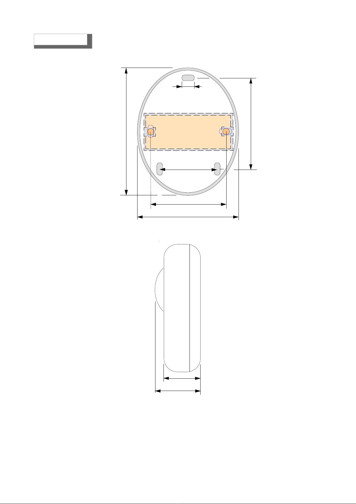
34 mm
50 mm
Embedded box 503
70 mm
105 mm
5 mm
115 mm
84 mm
115mm
Dimensions
Page 5
Turnonandtesting
30 cm
max
1-4 m
30 cm
max
1-4 m
N O ! N O !
Detector Gas
METHANE YES
Detector Gas
LPG
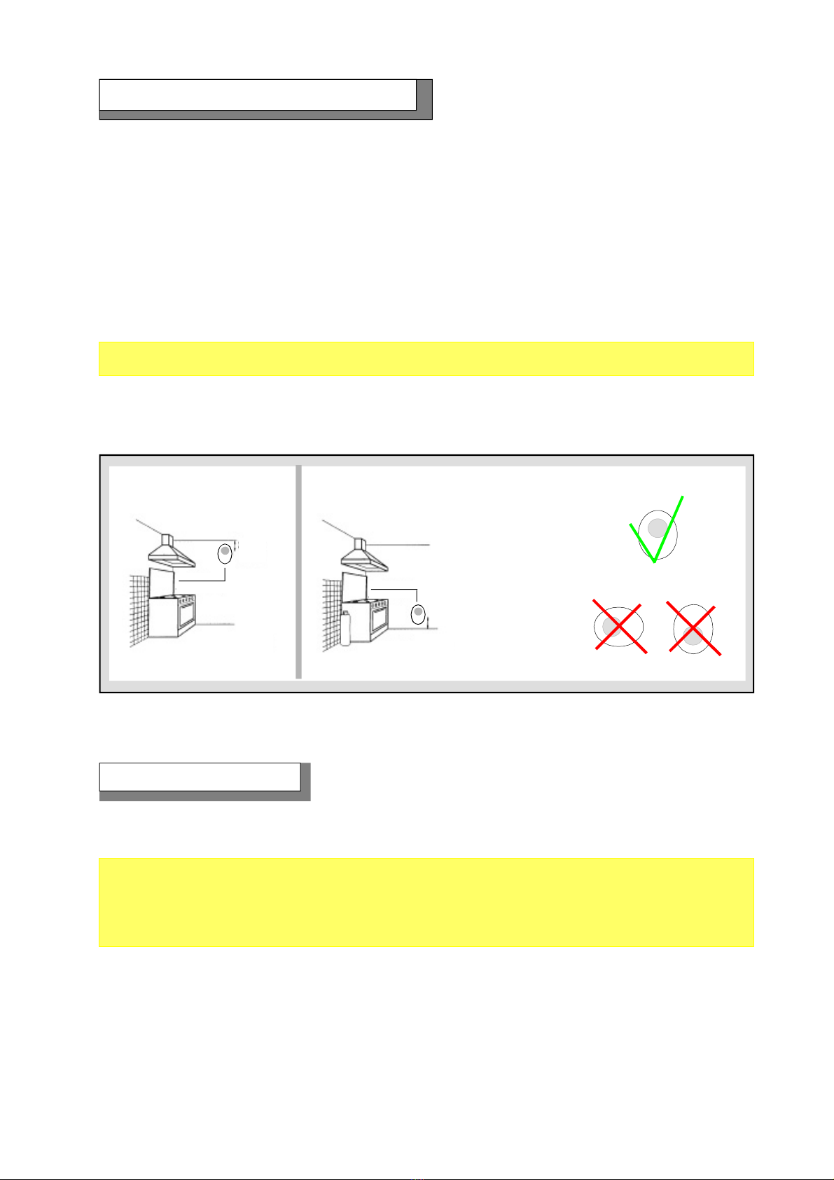
Installationmeasuresandpositioning
The position of the detector is a crucial factor for its correct functioning during gas detection.
In order to obtain the maximum results from a device and minimize the probability of false alarms,
it is recommended to follow this scheme and keep in mind the following general regulations.
The detector must be located at different heights, according to the type of gas. These heights are:
- 30 cm from the lowest point of the floor in order to detect heavy gases, LPG, etc.
- 30 cm from the highest point of the ceiling in order to detect light gases, Methane
- The detector should not be placed near the appliances to be controlled (boilers, burners, industrial
kitchens, etc.) but on the opposite wall.
- The detector should not be affected by smoke, vapour, etc. as they could distort its measurement.
It should be located away from sources of heat, ventilators or fans.
It must not be installed, on a wall in plasterworch.
It must be installed only on walls in masonry
Once the device has been turned on, the MAINS LED will start blinking for about 60 seconds, after
which it will remain ON. Now the GS920 is ready for detection of explosive gas.
After 24 hours from installation begin the self-learning antiseismic period (from this time the detector
MUST NOT be moved from the installation position for any reason).
After 10 days, the self-learning period is finished and the device is capable to detect seismic
movement.
Testing
Press the button near the detection capsule to simulate the presence of gas.
The ALARM LED lights up, and the relay shifts its functioning mode after 5 seconds. After the
alarm, the LED will turn off, the buzzer will stop, and the connected appliances will be turned off.
To complete the general test, issue gas from a pre-calibrated aerosol within 20% of L.E.L. Testing
using a common cigarette lighter could damage the sensor. This test should be carried out at least
once a year.
Page 6
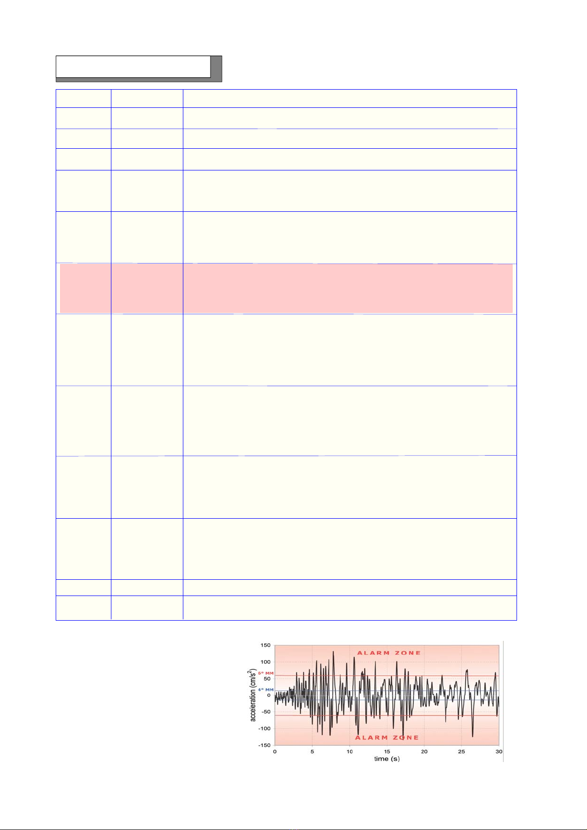
ModifiedMercalliScale
Earthquakes and relevant
triggerthresholds
MM Degree Accel (cm/s2) Description
1 1
2 2
3 3
Not felt by many people unless in favourable conditions.
Felt by a people at rest, especially on the upper floors of buildings or in
favourable position
Felt by people indoors. Hanging objects swing. Vibration like passing of
light trucks. Duration estimated. May not be recognized as an earthquake
Hanging objects swing. Vibration like passing of heavy trucks, or
sensation of a jolt like a heavy ball striking the walls. Standing motor cars
rock. Windows, dishes, doors rattle. Glasses clink. Crockery clashes.
In its upper range, wooden walls and frame creak.
4 15-20
5 30-40
6 60-70
7 100-150
8 250-300
9 500-550
10 >600
11 -----
12 -----
Felt outdoors; direction estimated. Sleepers wakened. Liquids disturbed,
some spilled. Small unstable objects displaced or upset. Doors swing,
close, open. Shutters, pictures move. Pendulum clocks stop, start,
change rate.
Felt by all. Many frightened and run outdoors. Persons walk unsteadily.
Windows, dishes, glassware broken. Knickknacks, books, etc., off shelves.
Pictures off walls. Furniture moved or overturned. Weak plaster and
masonry D cracked. Small bells ring (church, school).
DETECTOR TRIGGERED
Difficult to stand. Noticed by drivers of motor cars. Hanging objects quiver.
Furniture broken. Damage to masonry D, including cracks. Weak chimneys
broken at roof line.Fall of plaster, loose bricks, stones, tiles, cornices (also
unbraced parapets and architectural ornaments). Some cracks in masonry
C. Waves on ponds; water turbid with mud. Small slides and caving in along
sand or gravel banks. Large bells ring.Concrete irrigation ditches damaged.
Steering of motor cars affected. Damage to masonry C; partial collapse.
Some damage to masonry B; none to masonry A. Fall of stucco and some
masonry walls. Twisting, fall of chimneys, factory stacks, monuments,
towers, elevated tanks. Frame houses moved on foundations if not bolted
down; loose panel walls thrown out. Decayed piling broken off. Branches
broken from trees. Changes in flow or temperature of springs and wells.
Cracks in wet ground and on steep slopes.
General panic. Masonry D destroyed; masonry C heavily damaged,
sometimes with complete collapse; masonry B seriously damaged; general
damage to foundations; frame structures, if not bolted, shifted off
foundations; frames racked. Serious damage to reservoirs.
Underground pipes broken. Conspicuous cracks in ground. In alluvial areas
sand and mud ejected, earthquake fountains, sand craters.
Most masonry and frame structures destroyed with their foundations.
Some well-built wooden structures destroyed with their foundations. Some
well-built wooden structures and bridges destroyed. Serious damage to
dams, dikes, embankments. Large landslides. Water thrown on banks of
canals, rivers, lakes, etc. Sand and mud shifted horizontally on beaches
and flat land. Rails bent slightly.
Damage nearly total. Large rock masses displaced. Lines of sight and level
distorted. Objects thrown into the air.
Rails bent greatly. Underground pipelines completely out of service.

Page 7
The installation of the detector does not exemptfrom ...
... The compliance with all regulations concerning the characteristics, installation and use of gas
appliances. The ventilation of the spaces and the elimination of combustion products are
described in the UNI norms according to ART. 3 LAW 1083 / 71 and relevant legal provisions.
WARNING!Actionsto betakenincaseofalarm
1) Put out all free flames.
2) Close the main gas tap or the LPG cylinder tap.
3) Do not turn any lights on or off; do not turn on any electrical device or appliance.
4) Open windows and doors in order to increase ventilation.
If the alarm stops, its cause must be found and the relevant consequent measures taken.
If the alarm continues and the cause of gas presence cannot be found or removed, abandon the
building and call the emergency services when outside (fire department, distributors, etc.)
- If the device does not start up.
Check that the 230V power is correctly connected.
- If the fault LED lights up.
If the YELLOW LED is remains ON, check the detection capsule status. It is probably faulty and has
to be replaced. Call an authorized technician.
- If the detector is repeatedly issuing an alarm.
Check that there are no gas leaks.
If the alarm signal and the FAULT indicator light turn on together, proceed as in the previous
paragraph.
- If the detector is issuing an alarm and does not shut off the devices connected to it.
Check that the wiring is correct and that the jumper that carries power to the relay has been set
properly. All relays are free from electrical power. Check the drawing of the connections.
If other problems arise, a specialised and/or authorised technician and/or the Distributor of
BEINAT S.r.l. should be contacted directly.
Beforecallingatechnician
Page 8
Electricalconnections
WARNING
Before connecting to the mains power, ensure the voltage is correct.
Carefully follow the instructions and the connections according to Regulations in force, keeping
in mind that the signal cables should be laid separate from the power cables.
Power Supply
230 V AC N.O. impulse type electrovalve
12V DC supply
Optional
WARNING !
The Relay is free of voltage.
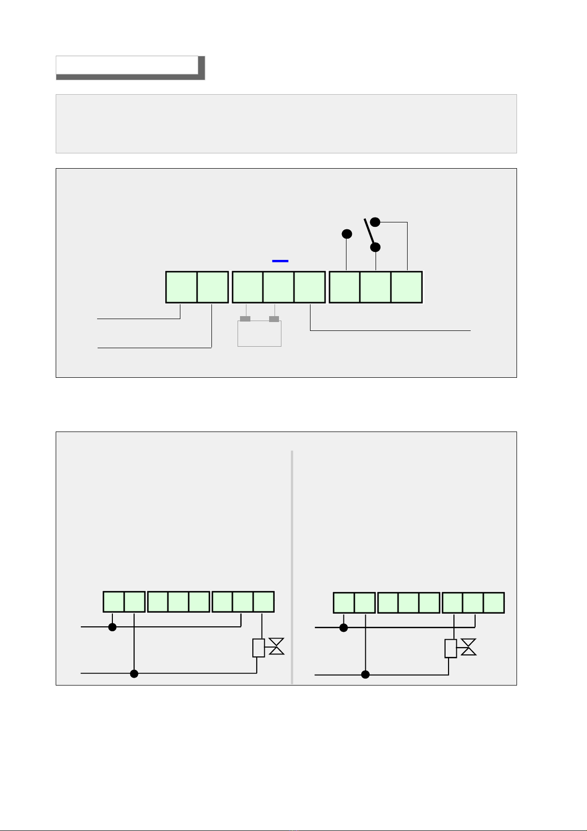
Connection Scheme of GS920 Detector
NC
C
NO
N
Ph
++
12 V
1 2 3 4 5 6 7 8
Without Intrinsic Safety With Intrinsic Safety
Normallyclosedelectrovalve230VAC
The Relay is free of voltage.
Range of relay contact 10A resistive
The electrovalve is a N.C. Automatic or manual
retrig
Note
To connect a N.O. Electrovalve swap the
connections between pin 8 and 6
The Relay is free of voltage.
Range of relay contact 10A resistive
The electrovalve is a N.C. Automatic or manual
retrig
Note
Is not allowed to connect a N.O. electrovalve
Power Supply
230 V AC Power Supply
230 V AC
Ph
N
Ph
N
1 2 3 4 5 6 7 8 1 2 3 4 5 6 7 8

Page 9
A 12VDC 1.2Ah battery can be connected to the GS920 gas detector.
The detector itself provide the needed charge for the battery.
The battery must be connected between the pin 3 and 4 (pin 3 is the positive, 4 is negative)
The battery option is useful for:
a) back-up of the gas detector with a duration of about 1 hour
b) supply a 12VDC electrovalve with a continuous absorption of less than 600mA
The Relay is free of voltage.
Range of relay contact 10A resistive
The drawn electrovalve is a Normally Open type with manual reset and with a power supply
of 12V 600mA MAX. The activation is impulsive.
Power Supply
230 V AC
Normallyopenelectrovalve230VACwithintrinsicsafety
++
Ph
N
1 2 3 4 5 6 7 8
The Relay is free of voltage.
Range of relay contact 10A resistive
The drawn electrovalve is a N.C. type with manual or automatic reset. The power supply is
12VDC 1A MAX with the help of a battery.
Normallycloseelectrovalve230VACwithoutintrinsicsafety
Power Supply
230 V AC
Ph
N
++
12 V
1 2 3 4 5 6 7 8
Electricalconnections
Page 10
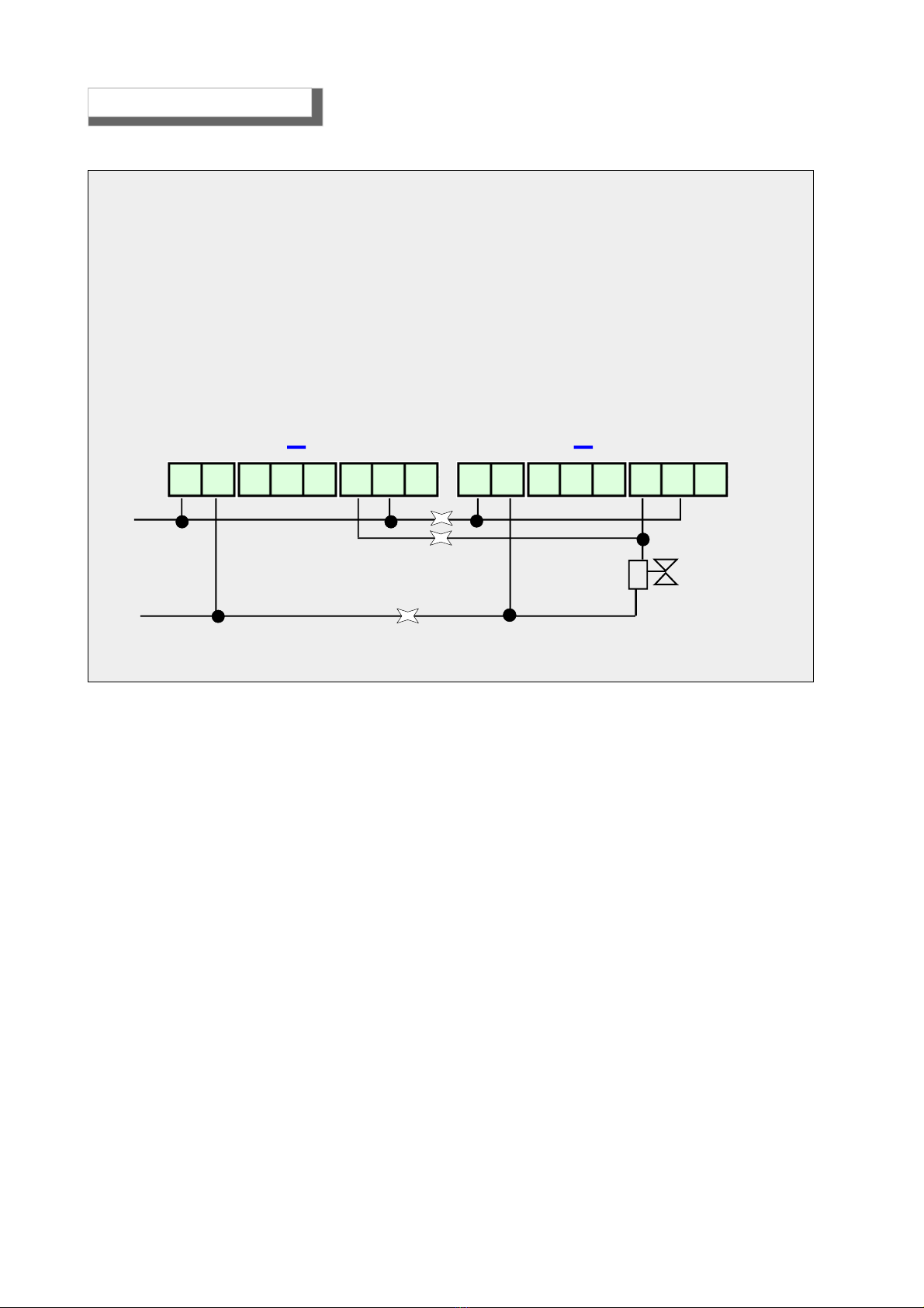
Connecting 2 Gas Detectors in Parallel
Ph
N
++++
1 2 3 4 5 6 7 81 2 3 4 5 6 7 8
Normallyopenelectrovalve230VACwithoutintrinsicsafety
The Relay is free of voltage.
Range of relay contact 10A resistive
The drawn electrovalve is a Normally Open type with manual reset and with a power supply
of 12V 600mA MAX. The activation is impulsive.
Power Supply
230 V AC
Electricalconnections

Page 11
Note
Made in Italy
TO BE FILLED AFTER INSTA LLATION
In agreement with our continuous development policy, we reserve the right to modify our products without notice.
Purchase Date
BEINAT S.r.l. Via G. Bossetto 3 - 10073, Ciriè (TO) - ITALY
Tel. 011.921.04.84 - Fax 011.921.14.77
E- mail - info@beinat.com - http:// www.beinat.com
INSURANCE. This device is insured by the SOCIETÀ REALE MUTUA for the PRODUCT'S GENERAL
LIABILITY up to a maximum of 1,500,000.00 EURO against damages caused by the device in case of
failures in functioning.
WARRANTY. The warranty term is 3 years from manufacturing date, in agreement with the following
conditions. The components acknowledged as faulty will be replaced free of charge, excluding the
replacement of plastic or aluminium cases, bags, packing, batteries and technical reports.
The device must arrive free of shipment charges to BEINAT S.r.l.
Defects caused by unauthorized personnel tampering, incorrect installation and negligence resulting
from phenomena outside normal functioning shall be excluded from the warranty.
BEINAT S.r.l. is not liable for possible damage, direct or indirect, to people, animals, or things; from
product faults and from its enforced suspension of use.
GS920 GAS DETECTOR Styling by b&b design
Stamp and signature of the dealer
Registration Number
Other manuals for GS920
1
Table of contents
Other BEINAT Gas Detector manuals

BEINAT
BEINAT CO922 User manual

BEINAT
BEINAT GSH246 Series User manual

BEINAT
BEINAT BXI32 User manual

BEINAT
BEINAT SG850 User manual

BEINAT
BEINAT SGM595-H2CH User manual

BEINAT
BEINAT GS913- V.6 User manual

BEINAT
BEINAT RGX100Q/Eg User manual

BEINAT
BEINAT CHECKER-24 User manual

BEINAT
BEINAT SG895 User manual

BEINAT
BEINAT NASE25 User manual

BEINAT
BEINAT CHCO User manual

BEINAT
BEINAT SG800 User manual

BEINAT
BEINAT RGX1002 User manual

BEINAT
BEINAT CHCO User manual

BEINAT
BEINAT GSH900 User manual

BEINAT
BEINAT GS911K User manual

BEINAT
BEINAT SGM595/A User manual

BEINAT
BEINAT NASE25/S User manual

BEINAT
BEINAT NASE25/K Instruction manual

BEINAT
BEINAT RGX100 User manual


