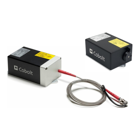
Hubner C-FLEX User manual

OWNERS MANUAL | C-FLEX | D0579-B DECEMBER 2019
C-FLEX
Compact | Flexible | Laser Combiner

2| 82
OWNERS MANUAL | C-FLEX | D0579-B DECEMBER 2019

3| 82
OWNERS MANUAL | C-FLEX | D0579-B DECEMBER 2019
CONTENTS
1. Introduction 5
2. Safety 5
2.1. General 6
2.2. Beam Hazards 7
2.1. Non-Beam Hazards 7
2.2. Accessible Emission and Eye Protection 8
2.3. System Safety Features 8
2.4. Equipment Safety 10
2.5. Warning and Identification Labels 11
3. Laser Combiner Operation Instructions 13
3.1. Preparing the installation space 14
3.2. Getting to know the parts 15
3.3. Mounting the C-FLEX on a heatsink or optical table 18
3.4. Connecting the cables from C-FLEX to auxillary equipment 21
3.5. Connecting the System Cables and starting emission 25
3.6. Verifying the Laser performance and System Alignment 28
3.7. Aligning the Fiber Coupler 32
3.8. Aligning the Combiner Optical Path 34
3.9. Preparing for Operation 41
3.10. Closedown operation 41
4. Cobolt Monitor™ Software 42
4.1. Installation 42
4.2. Software instructions 42
5. Controlling emission in Continuous Wave operation 46
5.1. RESTART and ABORT Button 46
5.2. Laser ON and Laser OFF Button 46
5.3. Optical output power level controls 47
5.4. Pause Emission with Commands 49
6. Controlling Emission with Modulation Mode Operation 51
6.1. Connecting the modulation cables 51
6.2. Cobolt 06-MLD Modulation inputs 52
6.3. Cobolt 06-DPL Modulation Inputs 53
6.4. AOM Modulation controls and input signals 55
7. System Overview 56
7.1. CDRH Configuration 56
7.2. OEM Configuration 56
7.3. C-FLEX Model identification and serial number 57
7.4. Laser model numbers 57
7.5. Operation via data port 58
7.1. System Interfaces 62

4| 82
OWNERS MANUAL | C-FLEX | D0579-B DECEMBER 2019
7.2. Laser Interfaces 62
7.3. Access panels 64
7.4. Thermal Management 64
7.5. AOM Driver Heat Sink 65
7.6. Power Supply Requirements 65
8. C-FLEX System Specifications 66
8.1. Combiner Optical Specifications 66
8.2. Configuration Specifications 66
8.3. Mechanical Interfaces 66
8.4. Operation and Environmental Specifications 66
8.5. Modulation Interfaces –Cobolt 06-01 Series 67
8.6. Modulation Interfaces –AOM Driver 67
8.7. Electrical Interfaces –AOM Driver 68
8.8. Electrical Interfaces –C-FLEX 68
8.9. Electrical Interfaces –Laser Controller 68
8.10. Compatible Laser Products 69
9. Mechanical Drawings 70
9.1. Laser combiner 70
9.2. Heat sink 71
9.3. Laser Controller 71
9.4. AOM Driver 72
10. Principle of laser beam alignment 73
10.1. Two pin-hole technique 73
10.2. Vertical alignment 74
10.3. Horizontal alignment 74
10.4. Angular alignment 75
10.5. Fiber alignment 76
10.6. Beam Path Alignment –Reference Laser Re-Alignment 77
11. Warranty and Maintenance 80
12. Service 80
13. Disclaimer 80
14. Compliance (CDRH models only) 81

5| 82
OWNERS MANUAL | C-FLEX | D0579-B DECEMBER 2019
Introduction
C-FLEX is a flexible and compact laser combiner that allows for integration of up to six different wavelengths on
a single platform, modulation options for all wavelengths, and configuration with either free beam or fiber
coupled beam delivery. C-FLEX is compatible with lasers from the Cobolt 06-01, 08-01 and 04-01 Series.*
C-FLEX is intended for stand-alone use in laboratory environments or for integration as an OEM component in
instruments for applications including fluorescence microscopy, flow cytometry, optogenetics, holography,
raman spectroscopy and photochemistry.
This manual is intended to be used as a tool to give the user a detailed understanding of how to operate and
align C-FLEX as well as the integrated lasers and auxillary equipment. The manual focuses on laser combiner
functionalities and with practical inclusions for the operation of the Cobolt lasers and Cobolt MonitorTM control
software and Acousto-optic modulators (AOMs). For more details on the functionality and performance of each
laser product or the auxillary equipment, the specific product manuals can be a valuable resource.
Below is a list of compatible Cobolt lasers product lines and links to the Cobolt website where the full list of
available products can be found. Contact your sales representative if the wavelength or modulation
performance you require is not available.
Cobolt 04-01 Series
Powerful, single frequency CW diode pumped lasers:
457 nm –660 nm up to 400 mW*
https://www.coboltlasers.com/lasers/dpss-lasers/
Cobolt 06-01 Series
Plug & play modulatable lasers:
405 nm –660 nm up to 300 mW
https://www.coboltlasers.com/lasers/diode-lasers/
Cobolt 08-01 Series
Compact narrow linewidth lasers:
405 nm –660 nm up to 200mW*
https://www.coboltlasers.com/lasers/narrow-linewidth-lasers/
*Compatibility with 785 and 1064 nm lasers not yet available.

6| 82
OWNERS MANUAL | C-FLEX | D0579-B DECEMBER 2019
Safety
General
The C-FLEX laser combiner’s laser classification is dependent on the lasers integrated into the laser combiner system.
The sum of the maximum emitted power of all lasers integrated into the laser combiner determines the laser
classification. Residual emission of any wavelength not specified on the warning label does not exceed Laser Class 1.
A Class IV (CDRH), Class 4 (IEC) laser combiner is capable of emitting more than 500 mW of laser radiation within
visible [400-700 nm] and Near Infrared (NIR) spectrum [700-1400 nm].
Symbols in the manual
WARNING –LASER RADIATION This symbol is used to call attention to important laser safety
information
WARNING –STATIC MAGNETIC FIELD This symbol is used to call attention to important
magnetic field safety information
CAUTION –GENERAL This symbol is used to call attention to important general operator and
equipment safety information
NOTICE –GENERAL This symbol is used to call attention to best practices when using the
equipment and does not indicate a hazard.

7| 82
OWNERS MANUAL | C-FLEX | D0579-B DECEMBER 2019
Beam Hazards
It is advised to perform a risk assessment for the facility and equipment prior to using the laser. In the case of
integration into a larger system, laser safety compliance must be evaluated in the end product. The device must be
handled by skilled personnel experienced with lasers, in a laboratory environment and with access to adequate laser
safety equipment. The laser clearly displays a yellow warning label that shows the location of the laser beam aperture.
This label must be visible unless the laser beam is totally enclosed.
WARNING Remove all watches, rings and other reflective jewelry before working with lasers.
Always wear the appropriate eye protection from the wavelengths integrated into the system. As
the system can be integrated with different laser lines after delivery, verify the accessible emission
wavelength and power before operating. Never look directly into a laser beam.
The highest risk of exposure is when aligning the beam. Eye hazards are related to direct exposure, specular
reflections and in the case of Class 4 lasers can even be related to diffuse reflections. Eye and skin exposure to direct
or reflected laser light is hazardous and may be extremely harmful. Always wear eye protection appropriate to the
beam wavelength(s) and intensity.
Laser radiation may ignite flammable materials and combustible gasses in the beam path and, in event of ignition,
fumes may be generated. All equipment used in close proximity to the laser beam should be suitably fire resistant and
the facility should be properly ventilated.
CAUTION Use of controls or adjustments or performance of any procedures other than those
specified herein may result in exposure to hazardous radiation.
Non-Beam Hazards
Strong Internal Magnet
The laser combiner safety interlock, described in section 2.3, and laser heads with optical isolators (Cobolt model
08-11) contain strong permanent magnets. Proceed with caution when positioning or servicing the laser
combiner near material which may be magnetized and when operating with tools which may be magnetized
(e.g. screwdriver) around the laser head. Users with implanted medical devices should stay back at least 30cm
(12 inches).

8| 82
OWNERS MANUAL | C-FLEX | D0579-B DECEMBER 2019
Accessible Emission and Eye Protection
The equations below describe how to use the nominal output power (mW) and beam area to calculate the irradiance
(W/cm2) and how to use the Warning label (Max) power (mW) and the Accessible Emission Limit (AEL) (mW) per laser
safety standard IEC 60825-1:2014 to calculated the required optical density (OD) for eye protection per wavelength.
Using a laser combiner requires a combination of eye protection that is specifically tailored to the device
configuration, be sure to consider all integrated wavelengths and power levels when selecting eye protection. Update
eye safety protocols and eye protections specifications when adding or removing a laser line from the combiner.
See the individual laser manuals for information on the accessible emission and maximum emission parameters. The
latest revision of all product manuals can be found via the Cobolt website www.coboltlasers.com.
System Safety Features
The laser combiner is equipped with all safety features required by the laser safety standard IEC 60825-1.
Safety Interlock
The safety interlock is an automatic mechanism designed to prevent access to emission of integrated lasers when the
access panel of the laser combiner is removed. When the access panel is removed the safety interlock circuit is open
and all emission is interrupted and no radiation will be accessible. The safety interlock has two magnetic switches that
must be actively closed to allow the laser combiner to function. When the lid of the combiner is in place, the magnets
on the lid will close the circuit. When working inside the combiner, the ‘Safety Interlock Overide Tool’ must be used
to override the circuit to allow the lasers inside the combiner to operate during alignment and maintenance.
WARNING –Laser Radiation accessible when safety interlock is defeated. Avoid skin and eye exposure
to direct or scattered radiation.
WARNING –The magnetic switches use strong magnets which are attached to the underside of the
access panel. Be aware of strong magnetic fields.
CAUTION –Alignment and maintenance of the lasers inside the C-FLEX should only be performed by
trained personnel with appropriate laser safety equipment.
9| 82
OWNERS MANUAL | C-FLEX | D0579-B DECEMBER 2019
Remote Interlock Connector
The remote interlock connector allows the connection of external controls placed at a distance from the laser
combiner. When the terminals of the connector are open-circuited, emission is interrupted and no radiation will be
accessible. The remote interlock connector permits easy addition of an external interlock in laser combiner
installation. After the remote interlock connector has been opened the laser will need to be reset by toggling the key
switch or disconnecting from and then reconnecting to the power supply. The signal level is between 0V and +5V with
a pull up resistor, and the current required to ground the remote interlock connector is 5 mA. The time delay in the
hardware is < 1 ms, but after filtering by the firmware the reaction time is extended to < 20 ms.
Manual Shutter (Beam Stop)
The laser combiner is equipped with a manual shutter, which functions as the beam stop, capable of preventing
human access to laser radiation. The aperture location and the open and close positions of the shutter are indicated
on the top surface of the laser combiner access panel. C-FLEX is delivered with the shutter fixed in the ‘closed’ position
using adhesive tape.
Key Control
The CE/CDRH compliant model comes with a key control switch which must be connected for the lasers to operate.
When the key is in the OFF position, all integrated lasers are prevented from emitting. The key must be actively turned
to the ON position each time the laser is powered on. When the key is removed from the system laser radiation is not
accessible. The key is only removable in the OFF position.
Laser Radiation Emission Warning / Status LED
The emission warning LEDs are located on the back panel of the laser combiner or laser controller, there are at least
two LEDs per laser line. The green “ON” LED is illuminated whenever the corresponding device is emitting or could
emit light. In case of a break in the interlock circuit or any other error state the red “ERR” LED is illuminated. If a laser
is off, no LED is illuminated.

10 | 82
OWNERS MANUAL | C-FLEX | D0579-B DECEMBER 2019
Equipment Safety
Back Reflection Sensitivity
Laser light reflected directly back into the laser head can cause instabilities in laser performance, instantaneous
damage to the laser diodes and a dramatic decrease in product lifetime. Cobolt 06-MLD lasers with a wavelength
greater than 600 nm are particularly sensitive, exercise extreme caution. If additional filters are installed make sure
that the corresponding anti-reflection coating is used to prevent back reflections into the laser head(s).
Electrostatic discharge
Always install the laser system to a properly grounded power outlet. Integrated lasers contain a laser diode which is
sensitive to electrostatic discharge (ESD).
Fiber Care
It is important to always make sure the fiber end-facet is clean before turning any of the lasers on and before
connecting the fiber connector in physical contact with another connector. Failure to do so may lead to irreparable
damage of the fiber end-face. Do not clean the fiber when the laser is on. We recommend using appropriate
equipment for fiber cleaning and inspection.

11 | 82
OWNERS MANUAL | C-FLEX | D0579-B DECEMBER 2019
Warning and Identification Labels
The upper face of the laser combiner contains a yellow label with laser safety warning and classification information,
the wavelength range and maximum power of each laser delivered originally with the C-FLEX. There are also labels
that show the location of the laser beam aperture, indicates the open and closed positions of the manual shutter and
the access panels. These labels must be visible unless the laser beam is totally enclosed. A label showing information
about the system model, serial number, manufacturer date and location, and the power supply voltage and current,
is located on the laser combiner. Laser combiners shipped to customers in the USA also contain a label of CDRH
compliance.
Laser Notice No. 50 Label
CDRH models shipped to USA
Additional Aperture Warning Label
Manufacturer Identification Labels
Access Panel Warning Labels
Aperture Laser Classification and
Emission Warning Label
CDRH models shipped to USA
Magnetic field Strength
Warning Label

12 | 82
OWNERS MANUAL | C-FLEX | D0579-B DECEMBER 2019
Label Placement

13 | 82
OWNERS MANUAL | C-FLEX | D0579-B DECEMBER 2019
Laser Combiner Operation Instructions
This section will cover the step-by-step process of getting a C-FLEX installed and ready for use. It is intended to
be conceise and instructive. More elaborate information about system configuration, performance
specifications, environmental requirements and alignment principles can be found in sections 7 through 10. It is
important to get to know the specific C-FLEX configuration before attempting to install it.
To know which Cobolt lasers are built into the C-FLEX laser combiner refer to the test protocol delivered with
the C-FLEX.
Determine if the C-FLEX should have been delivered with auxillary equipment which will need to be installed at
the same time in order for the combiner to function.
If the C-FLEX has Cobolt 04-01 lasers included the answer is YES! External controllers are required to run the
Cobolt 04-01 series lasers integrated into the C-FLEX. The controllers and all necessary cables are delivered with
the system.
If the C-FLEX has an integrated AOM, or possibly up to three, then the answer is also YES! The AOM Driver and
all necessary cables are delivered with the system.

14 | 82
OWNERS MANUAL | C-FLEX | D0579-B DECEMBER 2019
Preparing the installation space
Read section 2 : Safety before continuing and be sure the appropriate laser safety precautions have been taken
before installing and operating the C-FLEX laser combiner.
Decide if the C-FLEX is to be mounted directly on an optical table or on the custom heat sink. When installing,
allow for the space required to remove the access panel whilst aligning the optics inside the system. It will be
necessary to open the lid for both installation and alignment.
C-FLEX access panel space requirement
If using the heatsink mounted on an optical table, the heat sink must be fastened to the table before mounting
the C-FLEX to the heatsink.
C-FLEX Mounted on optical table (left) and mounted on a heat sink (right)
Use the test protocol delivered with the system to understand which lasers have been integrated into the C-
FLEX to be installed. The Cobolt Laser series is listed just below the serial number.

15 | 82
OWNERS MANUAL | C-FLEX | D0579-B DECEMBER 2019
Getting to know the parts
Check that all of the items listed in this section have been delivered and verify that the appropriate tools are
available.
C-FLEX Laser Combiner System parts
❖C-FLEX Laser combiner with integrated lasers and fiber coupler (in case of the fiber coupled option)
are delivered assembled. The fiber is not mounted at delivery.
❖Optional Optical Fiber (not mounted at delivery)
❖C-FLEX System Power Supply 15VDC 7A
❖C-FLEX System Data Cable USB-B/USB-A
❖Keys

16 | 82
OWNERS MANUAL | C-FLEX | D0579-B DECEMBER 2019
❖Remote interlock plug (for short circuiting the remote interlock connector)
❖Fixation bolts (3 pieces) –Both metric and imperial screws are delivered but only 3 will be used for
mounting.
If the C-FLEX contains a Cobolt 04-01 series laser or an AOM it will be delivered with auxillary equipment.
Cobolt 04-01 Laser Controller and Cables
❖Cobolt 04-01 Laser Controller(s) –one per Cobolt 04-01 Series laser head
❖Cobolt 04-01 Controller cable (26-pin D-SUB) –one per Cobolt 04-01 Series laser head
❖Control I/O Cable (8- pin to 6-pin Molex connector and 2-pin molex connector)
❖Controller data cable (Mini USB to C-FLEX back panel)

17 | 82
OWNERS MANUAL | C-FLEX | D0579-B DECEMBER 2019
❖Laser power supply cable (Kycon 4 pin connector to C-FLEX back panel)
AOM Driver and Cables
❖AOM Driver
❖AOM Driver Cable –Sub-D 15 to 2x 5mm DC Socket
❖AOM RF Input Cables
❖AOM Power Supply 24 V
❖AOM 5V DC Supply

18 | 82
OWNERS MANUAL | C-FLEX | D0579-B DECEMBER 2019
Alignment tools
❖Aperture mounted pinhole alignment tool (12749)
❖Steering mirror mounted pinhole alignment tool (12748)
❖Safety Interlock override tool for alignment
Installation tools –Included :
❖Hexagon Screwdriver - 1.5 mm
❖Hexagon Screwdriver - 2.5 mm
❖Torx Screwdriver –T20
❖Phillips Screwdriver –PH2
❖Slotted Screwdriver –6.5 mm
Verification and Alignment tools –Not included
❖Fast power meter or photodiode
❖Detector card
❖Beam profile camera
Control Software
❖Cobolt Monitor™ laser control software
Cobolt Monitor™ can be downloaded from the Cobolt website : www.coboltlasers.com/downloads .
The control software is a stand alone executable, it can be run directly without any installation. If using
an older version of windows it may be necessary to install the Cobolt USB drive, which can also be
downloaded from the Cobolt website. See section 4 : Cobolt Monitor™ Software for more information.
❖Beam overlap calculation template : www.coboltlasers.com/downloads

19 | 82
OWNERS MANUAL | C-FLEX | D0579-B DECEMBER 2019
Mounting the C-FLEX on a heatsink or optical table
WARNING –When the access panel is removed the safety interlock circuit will be open and prevent
emission. At this point is not necessary to power the C-FLEX, for added safety it is recommended
not to connect any cables to the C-FLEX while mounting.
1. If mounting the C-FLEX onto the heat sink, mount the heat sink to the optical bench before mounting
the C-FLEX.
2. Remove the four screws from the access panel of the C-FLEX. Keep them in a safe place, they will be
replaced after fixation and alignment.

20 | 82
OWNERS MANUAL | C-FLEX | D0579-B DECEMBER 2019
NOTICE –The fixation bolts do not require the removal of any parts mounted within the C-FLEX!
Take care not to bump the mirrors, it may affect the alignment accuracy.
NOTICE –Use ONLY the delivered spring loaded bolts, improper mounting of the C-FLEX may
introduce mechanical stress that will have a negative impact on performance.
3. Use the provided fixation bolts and springs to fix the C-FLEX to the mounting surface, either directly
on the optical bench or on the heat sink. The fixation bolts are designed to hold the laser combiner in
place while allowing for thermal expansion during operation. Place the bolts in the order indicated on
the illustration and do not tighten completely until all three bolts are partially in place.
4. Replace the access panel before connecting the cables. Tighten all four screws to secure the access
panel safely in place.
Table of contents
Other Hubner Measuring Instrument manuals

Hubner
Hubner HM35 User manual

Hubner
Hubner Cobolt Odin Series User manual

Hubner
Hubner Cobolt DPSS User manual

Hubner
Hubner Cobolt 05-01 Series User manual

Hubner
Hubner Cobolt 04-01 Series User manual

Hubner
Hubner Cobolt Tor Series User manual

Hubner
Hubner Cobolt 06-MLD 940 nm User manual

Hubner
Hubner FG 2 Series Product guide

Hubner
Hubner Cobolt 06-01 Series User manual